Table of Contents
Advertisement
Quick Links
See also:
Service Manual
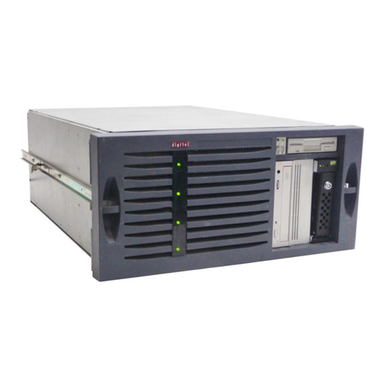
AlphaServer 800
User's Guide
Order Number:
EK–ASV80–UG. B01
This manual is intended for the user of the DIGITAL AlphaServer
800 server system. It describes the operation of the system, explains
the use of the SRM and the AlphaBIOS consoles, gives procedures
for component replacements, and discusses troubleshooting.
Digital Equipment Corporation
Maynard, Massachusetts
Advertisement
Table of Contents
Troubleshooting

Related Manuals for Digital Equipment AlphaServer 800


Summary of Contents for Digital Equipment AlphaServer 800
- Page 1 AlphaServer 800 User’s Guide Order Number: EK–ASV80–UG. B01 This manual is intended for the user of the DIGITAL AlphaServer 800 server system. It describes the operation of the system, explains the use of the SRM and the AlphaBIOS consoles, gives procedures for component replacements, and discusses troubleshooting.
- Page 2 The software, if any, described in this document is furnished under a license and may be used or copied only in accordance with the terms of such license. No responsibility is assumed for the use or reliability of software or equipment that is not supplied by Digital Equipment Corporation or its affiliated companies.
- Page 3 This device complies with Part 15 of the FCC rules. Operation is subject to the following two conditions: (1) this device may not cause harmful interference, and, (2) this device must accept any interference received, including interference that may cause undesired operation. Any changes or modifications made to this equipment may void the user’s authority to operate this equipment.
-
Page 5: Table Of Contents
Contents Preface ......................xiii Chapter 1 Overview System Architecture .................1-2 System Features ..................1-4 System Parts.....................1-6 Control Panel ...................1-8 Rear Panel Connections ................1-11 Storage Device LEDs ................1-13 Console ....................1-15 System Options ..................1-16 System Specifications................1-18 1.10 Acoustical Data ..................1-21 Chapter 2 Installing a System into a Cabinet Shipment Box...................2-2 Preparing the System ................2-4 Marking the Installation Area in the Cabinet ..........2-6... - Page 6 Chapter 3 Installing the System System Setup Overview................3-1 Selecting a System Location ..............3-1 3.2.1 Environmental Conditions ..............3-2 3.2.2 Power Requirements................3-3 Identifying Accessories ................3-4 Connecting the System ................3-5 Connecting to Network Hardware ............3-6 Locking Your System................3-7 Chapter 4 Operating the System Powering Up the System ................4-2 Booting Windows NT................4-10 Booting the Operating System for the First Time ........4-12...
- Page 7 6.2.5 Changing Environment Variables ............6-13 6.2.6 Depositing and Examining Data ............6-16 6.2.7 Reading a File .................6-19 6.2.8 Initializing the System ..............6-20 6.2.9 Finding Help ...................6-22 6.2.10 Switching from SRM to the AlphaBIOS Console ......6-23 SRM Console Security Features .............6-24 6.3.1 The Set Secure Command ...............6-24 6.3.2 The Set Password Command ............6-24...
- Page 8 Resetting the RMC to Factory Defaults ............8-9 Remote Management Console Commands ..........8-10 RMC Troubleshooting Tips ..............8-21 Chapter 9 Using the Hard Disks SCSI Bus Controller .................9-1 Configuration ...................9-1 External SCSI Expansion .................9-4 Chapter 10 Installing Components 10.1 Preparing to Install or Remove Components ...........10-2 10.2 Removing and Installing Memory DIMMs ..........10-6 10.3...
- Page 9 10-1 The show config Command Display .............10-14 11–1 Test Command ..................11-7 Figures Block Diagram of the AlphaServer 800 Server System ......1-2 AlphaServer 800 System Parts..............1-6 Control Panel ...................1-8 Rear Panel Connections ................1-11 Hard Disk Drive LEDs ................1-13 Floppy Drive Activity LED ..............1-14 CD-ROM Drive Activity LED..............1-14...
- Page 10 Installing the Cable Management Bracket ..........2-12 Installing the Interlock Mechanism ............2-14 Cable Loop at the Rear of the System .............2-16 System Dimensions and Service Area ............3-2 Power Supply Requirements ..............3-3 System Accessories ..................3-4 System Connections .................3-5 Network Connections ................3-6 System Lock and Key................3-7 Windows NT Power-Up Display ..............4-2 AlphaBIOS Boot Screen.................4-10 Memory Banks ..................5-8...
- Page 11 11–1 J1 Jumper on the CPU Card (Normal Position) ........11-24 Tables AlphaServer 800 Documentation...............20 System Status Indicated by the Control Panel LEDs .......1-10 System Specifications................1-18 AlphaServer 800 Acoustical Data ............1-21 3–1 Environmental Conditions ................3-2 3–2 System Accessories ..................3-5 5–1 Resetting Environment Variables ............5-16 5–2...
- Page 12 11–2 Error Beep Codes ...................11-5 11–3 Troubleshooting Power Problems ............11-8 11–4 Troubleshooting Console Problems ............11-9 11–5 Troubleshooting Boot Problems ............11-10 11–6 Problems Detected by the Operat ing System ........11-12 11–7 Troubleshooting Mass Storage Problems ..........11-13 11–8 Troubleshooting EISA/ISA Bus Problems ..........11-16 11–9 Troubleshooting PCI Bus Problems ............11-17 11–10...
-
Page 13: Preface
Preface Intended Audience This manual is intended for the operator of the AlphaServer 800 system. Document Structure This manual uses a structured documentation design. Topics are organized into small sections for efficient online and printed reference. Each topic begins with an abstract. -
Page 14: Alphaserver 800 Documentation
• Chapter 11, Troubleshooting, provides basic troubleshooting information for the system. Documentation Titles Table 1 lists the books in the AlphaServer 800 documentation set. Table 1 AlphaServer 800 Documentation Title Order Number AlphaServer 800 System Info Kit QZ–00XAA–GW... -
Page 15: Chapter 1 Overview
Chapter 1 Overview The AlphaServer 800 system is a high-performance, uniprocessor system intended for use as a local area network (LAN) server or commercial applications server. Ideal uses for the AlphaServer 800 system include the following: • Application server−To run applications such as relational databases, electronic mail, and communications •... -
Page 16: System Architecture
1.1 System Architecture The AlphaServer 800 system is a low-end server that offers PCI and EISA bus options on a single system board. Figure 1-1 shows the architecture of the system. Figure 1-1 Block Diagram of the AlphaServer 800 Server System... - Page 17 The AlphaServer 800 system is housed in an enclosure containing the motherboard, CPU daughter card, other logic modules, and power supply with internal fans. The enclosure allows for up to four internal mass-storage devices, with up to four removable media devices, one of which is a 3.5-inch floppy drive. The control panel includes Halt, Reset, and On/Off buttons.
-
Page 18: System Features
Windows NT Flexible Packaging Single enclosure available as free- standing pedestal or rack-mountable box. System Expansion • Flexible memory architecture Provides a 256-bit memory data path. Allows incremental memory expansion from 32 Mbytes to 2 Gbytes. 1-4 AlphaServer 800 User’s Guide... - Page 19 • Three 32-bit PCI slots, one shared Accommodates industry-standard option 64-bit PCI/EISA slot, and two cards such as Ethernet, FDDI, SCSI, and dedicated EISA slots modems. • Capacity for eight internal storage A modular storage system accommo- devices dates up to four 3.5-inch full-height SCSI devices.
-
Page 20: System Parts
1.3 System Parts Figure 1-2 identifies the main parts of the system in a pedestal version. The enclosure has a top cover and a side panel. Figure 1-2 AlphaServer 800 System Parts IP00110B 1-6 AlphaServer 800 User’s Guide... - Page 21 The main components of an AlphaServer 800 system are: ² Removable side cover of system enclosure ³ Floppy diskette drive ´ Removable media drives µ Lower and upper doors ¶ Control panel · Hard disk drives ¸ System board ¹...
-
Page 22: Control Panel
1.4 Control Panel The control panel provides system controls and status indicators on the front of the AlphaServer 800 enclosure. Figure 1-3 Control Panel IP00039-97 1-8 AlphaServer 800 User’s Guide... - Page 23 The control panel consists of three pushbutton controls and two LED indicators: • Power On/Off button • Halt button • Reset button • Green Power OK indicator • Amber Halt indicator The functions provided by these pushbutton conrols and indicators are discussed next.
-
Page 24: System Status Indicated By The Control Panel Leds
Fan failure • Overtemperature failure • Power supply failure System is powered on. System power is on and Halt button is pressed in or a halt in command has been issued at the remote management console. 1-10 AlphaServer 800 User’s Guide... -
Page 25: Rear Panel Connections
1.5 Rear Panel Connections Rear panel ports and slots are shown in Figure 1-4. Figure 1-4 Rear Panel Connections IP00030A-97 Overview 1-11... - Page 26 Serial port/terminal port (COM1) — To console terminal. This is an M MJ with data leads only. © AC switch 115V/220VKey — Should be pointing to the correct input AC voltage. ª SCSI breakouts — To SCSI devices « Security hole — To secure the system 1-12 AlphaServer 800 User’s Guide...
-
Page 27: Storage Device Leds
1.6 Storage Device LEDs Storage device LEDs indicate the status of the device. Figure 1-5 shows the hard disk drive LEDs. Figure 1-5 Hard Disk Drive LEDs DiskPresent Fault Activity IP00080 Function Activity (green) When lit indicates disk activity. Fault (amber) Reserved for future use. -
Page 28: Floppy Drive Activity Led
Figure 1-6 Floppy Drive Activity LED Activity LED IP00081-97 Figure 1-7 shows the Activity LED of the CD-ROM drive. When lit, it indicates that the drive is active. Figure 1-7 CD-ROM Drive Activity LED Activity LED IP00082-97 1-14 AlphaServer 800 User’s Guide... -
Page 29: Console
This allows remote access to the control panel functions. It also allows maintenance of system environmental conditions and the setup of alerts for changes in certain operating conditions. Because the AlphaServer 800 system supports multiple operating systems, it offers two separate interfaces to the console program: •... -
Page 30: System Options
1.8 System Options The AlphaServer 800 system supports storage options, PCI/EISA/ISA options, and memory options. Internal Options The AlphaServer 800 system supports the following types of internal options: • Storage • PCI/EISA/ISA • Memory Storage devices include: • One diskette drive •... - Page 31 If you are an Internet participant, you can obtain information related to the AlphaServer 800 system through the DIGITAL FTP archive: ftp://ftp.digital.com/pub/Digital/Alpha/systems/as800/ The WWW site for technical documentation and supply lists is: http://www.digital.com/alphaserver/tech_docs/alphasrv800/...
-
Page 32: System Specifications
1.9 System Specifications Table 1-2 gives the AlphaServer 800 system specifications. Table 1-2 System Specifications Physical Characteristics Pedestal Height 45 cm (17.7 in.) Width 22.6 cm (8.9 in.) Depth 65.8 cm (25.9 in.) Weight Typical: 24.5 kg (54 lb) Max: 28 kg (62 lb) - Page 33 Table 1-2 System Specifications (Continued) Clearances Operating Service Pedestal Front 75 cm (29.5 in.) 75 cm (29.5 in.) Rear 15 cm (5.9 in.) 75 cm (29.5 in.) Left side None 75 cm (29.5 in.) Right side None 5 cm (2 in.) Rackmount See requirements of Slides forward 68.6 cm (27...
- Page 34 88 to 132 Vac/176 to 264 Vac Power Supply Phase Single/Single Nominal Frequency 60 Hz/50 Hz Frequency Range 57-63 Hz/47-53 Hz RMS Current (steady state) at Nominal Voltage 7.0 amps/3.0 amps Max Power Consumption 380 Watts 1-20 AlphaServer 800 User’s Guide...
-
Page 35: Acoustical Data
1.10 Acoustical Data Table 1-3 gives the noise declaration for an AlphaServer 800 system with diskless, 1-Gbyte or 2-Gbyte RZ28M configurations. Table 1-3 AlphaServer 800 Acoustical Data Acoustics — Declared Values per ISO 9296 and ISO 7779 Sound Power Level... -
Page 37: Chapter 2 Installing A System Into A Cabinet
Chapter 2 Installing a System into a Cabinet This chapter gives installation procedures for a rackmount system. Sections are: • Shipment Box • Preparing the System • Marking the Installation Area in the Cabinet • Preparing the Cabinet • Installing the System •... -
Page 38: Shipment Box
2.1 Shipment Box The rackmount system is shipped in a single box. Figure 2-1 shows the hardware shipped with the system. Figure 2-1 Unpacking the Rackmount System IP00058 AlphaServer 800 User’s Guide... - Page 39 The rackmount system is shipped in a single box that contains the following items: • The AlphaServer 800 system already assembled • Front bezel assembly—P/N 70-33178-01 • Poly bag containing mounting hardware The mounting hardware consists of the following items:...
-
Page 40: Preparing The System
2.2 Preparing the System Prepare the system as described in the following procedure. Use Figure 2-2 as a guide. Figure 2-2 Preparing the System for Rackmount IP00055B-97 AlphaServer 800 User’s Guide... - Page 41 Prepare the system as follows: CAUTION: The chassis slides are lightly greased. Handle them carefully to avoid soiling of clothing. ² 1. Attach a front mounting bracket to each side of the system using two M4 x 10 mm screws per bracket. ³...
-
Page 42: Marking The Installation Area In The Cabinet
2.3 Marking the Installation Area in the Cabinet Determine the installation area as shown in Figure 2-3. Figure 2-3 Rackmount Installation Area NEMA Metric 0.500 inch 25 mm 0.625 inch 25 mm 0.625 inch 0.500 inch 4.375 inch 4.375 inch IP00064 AlphaServer 800 User’s Guide... - Page 43 The installation of the rackmount system requires 8.75 inches (5U) of vertical height in the cabinet. 1. Mark the midpoint hole on the vertical rail as shown in Figure 2-3. The midpoint hole must be selected so that the holes immediately above and immediately below are equidistant (.625 inches).
-
Page 44: Preparing The Cabinet
2.4 Preparing the Cabinet Prepare the cabinet as described in the following procedure. Use Figure 2-4 as a guide. Figure 2-4 Preparing the Cabinet for Rackmount IP00062B AlphaServer 800 User’s Guide... - Page 45 Prepare the cabinet as follows: 1. Attach slide brackets to the cabinet rails. ² ³ Attach slide bracket to each of the four vertical rails of the cabinet using ´ two 10-32 screws and one nut bar per slide bracket. The slide bracket installs behind the vertical rail of the cabinet and the nut bar installs behind the slide bracket, as shown in Figure 2-4.
-
Page 46: Installing The System
2.5 Installing the System Install the system as described in the following procedure. Use Figure 2-5 as a guide. Figure 2-5 Installing the System IP00065C-97 2-10 AlphaServer 800 User’s Guide... - Page 47 Observe the following precautions before you begin to install the system into the cabinet: CAUTION: 1. Make sure that all devices are pushed into the cabinet and no device is disengaged. 2. Activate the stabilizer foot of the cabinet, if the cabinet is so equipped, or provide other means to stabilize the cabinet before installation of the system.
-
Page 48: Installing The Cable Management Bracket
2.6 Installing the Cable Management Bracket Install the cable management bracket to the rear rails of the cabinet as described in the following procedure. Use Figure 2-6 as a guide. Figure 2-6 Installing the Cable Management Bracket IP00067B 2-12 AlphaServer 800 User’s Guide... - Page 49 The cable management bracket has 1.75-inch (1U) spacing (bottom hole to top hole) and 25 mm spacing (bottom hole to middle hole). Install the cable management bracket to the rear of the cabinet with four 10-32 U- nuts and four 10-32 screws.as follows: 1.
-
Page 50: Installing The Interlock Mechanism
DIGITAL cabinet equipped with the interlock system. If another type of cabinet is used, the installer must ensure cabinet stability. Install the interlock mechanism as described in the following procedure, using Figure 2-7 as a guide. Figure 2-7 Installing the Interlock Mechanism IP00068 2-14 AlphaServer 800 User’s Guide... - Page 51 Install the system into the interlock mechanism of the cabinet as follows: ² 1. Install the actuator trip bracket on the rear of the system with two M4x10 mm screws. ³ 2. Free up the vertical bar of the interlock mechanism. ´...
-
Page 52: Connecting The Cables
When making the cable connections, make sure to leave approximately a 76-cm (30-inch) long segment of cable free so that the system can slide forward. See Figure 2-8. Figure 2-8 Cable Loop at the Rear of the System 38 cm (15 in) IP00067C 2-16 AlphaServer 800 User’s Guide... - Page 53 Make the cabinet rear connections as follows: 1. Attach a rear cable first to the cabinet management bracket with a tie-wrap making sure that a segment of at least 30 inches of cable is available for extension so that the rackmount system can be pulled out of the cabinet. 2.
-
Page 55: Chapter 3 Installing The System
Chapter 3 Installing the System This chapter explains how to set up and install your system. The following topics are discussed: • System Setup Overview • Selecting a System Location • Identifying Accessories • Connecting the System • Connecting to Network Hardware •... -
Page 56: Environmental Conditions
Allow a minimum clearance of 15 cm (6 inches) at the rear of the system to allow for air exhaust and cable egress. Allow 70 cm (27 inches) at the front for system access and air intake. AlphaServer 800 User’s Guide... -
Page 57: Power Requirements
3.2.2 Power Requirements Your system is factory-set to the voltage indicated on the yellow label over the receptacle. After removing the label, verify that the voltage setting is correct for this installation. Figure 3-2 shows the power supply requirements and connection. CAUTION: Powering the system on with the wrong power setting may cause damage to the power supply. -
Page 58: Identifying Accessories
Figure 3-3 shows the accessories that are included with the system. Table 3–2 describes the accessories. Optional Accessory An optional accessory that you may need for your modem is the 9-pin to 25-pin PC to modem cable. Figure 3-3 System Accessories IP00091 AlphaServer 800 User’s Guide... -
Page 59: Connecting The System
Table 3–2 System Accessories Accessory Description ” Pedestal system unit keys (2) Locks and unlocks the pedestal lower door • User’s Guide and Installation Card Installation and operation information – EISA Configuration Utility kit Runs the EISA Configuration Utility — Mouse PS/2-style, 3-button mouse ˜... -
Page 60: Connecting To Network Hardware
Your system supports various network options. Generally, the system is configured with 10/100Base-T Ethernet networks as shown in Figure 3-5. With appropriate options, you can also connect to ThinWire, FDDI, and AUI Ethernet, and token ring networks. Figure 3-5 Network Connections IP00093 AlphaServer 800 User’s Guide... -
Page 61: Locking Your System
3.6 Locking Your System Pedestal systems are protected by a key lock located on the lower front door that prevents unauthorized access. The removable media devices and the system control panel are always accessible through the upper front door as show in Figure 3-6. The figure shows the door in the locked position. -
Page 63: Chapter 4 Operating The System
Chapter 4 Operating the System This chapter explains how to start and stop your system. It assumes that you have set up the hardware and made all necessary connections. Sections in this chapter are: • Powering Up the System • Booting DIGITAL UNIX •... -
Page 64: Powering Up The System
Figure 4-1 Windows NT Power-Up Display AlphaBIOS Version 5.26 Please select the operating system to start: Windows NT Server 4.00 to move the highlight to your choice. Press Enter to choose. Alpha Press <F2> to enter SETUP PK-0728A-96 AlphaServer 800 User’s Guide... - Page 65 Example 4–1 DIGITAL UNIX and OpenVMS Power-Up Display ff.fe.fd.fc.fb.fa.f9.f8.f7.f6.f5.ef.df.ee.f4. probing hose 0, PCI probing PCI-to-EISA bridge, bus 1 bus 0, slot 5 -- pka -- QLogic ISP1020 bus 0, slot 6 -- vga -- S3 Trio64/Trio32 bus 0, slot 11 -- ewa -- DECchip 21041-AA bus 0, slot 12 -- pkb -- DEC KZPSA bus 0, slot 13 -- dra -- Mylex DAC960 ed.ec.eb..ea.e9.e8.e7.e6.e5.e4.e3.e2.e1.e0.
- Page 66 DIGITAL UNIX or OpenVMS operating system boots. If the system is running the Windows NT operating system (the os_type environment variable is set to nt), the SRM console loads and starts the AlphaBIOS console. AlphaServer 800 User’s Guide...
- Page 67 Startup Test Fail If the system fails the startup tests, do the following: 1. Turn the system unit off, wait approximately 15 seconds, and then turn it on again. 2. If the system continues to fail the startup tests, or emits error beep codes and halts, refer to Chapter 11, Troubleshooting, for possible reasons.
- Page 68 CPU jumping to bootstrap code ´ Digital UNIX boot - Mon Jan 27 19:35:15 EST 1997 Loading vmunix ... The system is ready. Digital UNIX Version V4.0 (les058.dec.com) console login: AlphaServer 800 User’s Guide...
- Page 69 ² The show device command displays device information. For some device types, the full device name is required. (These are devices that have bus node numbers and channel numbers that are other than 0.) See Section 6.2 for a description of the show device command and the device naming convention. ³...
-
Page 70: Booting Openvms
SCSI Bus ID 7 2.10 pkc0.7.0.2003.0 PKC0 SCSI Bus ID 7 2.10 ³ pkd0.7.0.13.0 PKD0 SCSI Bus ID 7 >>> sho boot * boot_arg0 boot_arg1 boot_dev dka200.2.0.5.0 boot_file boot_osflags boot_reset bootdef_dev dka4000.4.0.5.0 booted_dev booted_file booted_osflags Continued on next page AlphaServer 800 User’s Guide... - Page 71 Example 4–3 Booting OpenVMS (Continued) ´ >>> boot µ CPU 0 booting (boot dka4.4.0.5.0 -flags 0) Building FRU table block 0 of dka4.4.0.5.0 is a valid boot block reading 1002 blocks from dka4.4.0.5.0 bootstrap code read in base = 200000, image_start = 0, image_bytes = 7d400 initializing HWRPB at 2000 initializing page table at 1f2000 initializing machine state...
-
Page 72: Booting Windows Nt
Figure 4-2 AlphaBIOS Boot Screen AlphaBIOS Version 5.26 Please select the operating system to start: Windows NT Server 4.00 to move the highlight to your choice. Press Enter to choose. Alpha Press <F2> to enter SETUP PK-0728A-96 4-10 AlphaServer 800 User’s Guide... - Page 73 The setting of the SRM os_type environment variable determines if AlphaBIOS is loaded and started on reset and power-up. If os_type is set to nt, after the power-up display the SRM console is loaded and started, and it then loads and starts the AlphaBIOS console.
-
Page 74: Booting The Operating System For The First Time
• Run the EISA Configuration Utility. • Check required environment variable settings. • Change the way your system powers up or boots. • Verify the system configuration. 4-12 AlphaServer 800 User’s Guide... - Page 75 Running the EISA Configuration Utility If you have added, removed, or moved an EISA or ISA card, you must run the EISA Configuration Utility before booting the operating system. Refer to Chapter 7 on how to run a configuration utility. Checking Required Environment Variable Settings You may also want to check that settings for the following variables match your configuration.
- Page 76 Windows NT (AlphaBIOS) console to the DIGITAL UNIX and OpenVMS (SRM) console. See Chapter 7 on switching to the DIGITAL UNIX and OpenVMS console. NOTE: Switch back to the Windows NT (AlphaBIOS) console before booting the Windows NT operating system. 4-14 AlphaServer 800 User’s Guide...
-
Page 77: Powering Off The System
4.6 Powering Off the System You may not need to turn the system off to resolve system hangs or similar problems. You can often recover from hangs or other problems by pressing the Reset button on the operator control panel or by issuing a reset command at the remote management console prompt. -
Page 79: Chapter 5 Reconfiguring The System
Chapter 5 Reconfiguring the System This chapter covers the following topics: • AlphaBIOS Console Configuration Options • SRM Console Configuration Commands • Memory Configuration • Network Configuration • EISA and ISA Options • EISA Configuration Utility (ECU) • Running ECU •... -
Page 80: Alphabios Console Configuration Options
AlphaServer 800 Family Processor: Digital Alpha 21164, Revision 4.0 (1 Processor) Speed: 400 MHz Memory: 256 MB Floppy Drive A: 3.5" 1.44 MB Floppy Drive B: None Keyboard: U.S. 101-key keyboard AlphaBIOS Version: 5.26 ESC=Exit PK-0731B-96 AlphaServer 800 User’s Guide... - Page 81 Going through each item of the System Configuration Display menu, you can examine how each part of your system is configured. Refer to Chapter 7 for details of system configuration displays. NOTE: You can also list options recognized by your system by entering the DIGITAL UNIX and OpenVMS commands described in the next section, SRM Console Configuration Commands.
-
Page 82: Srm Console Configuration Commands
Bank 1 = 64 Mbytes(16 MB Per DIMM) Starting at 0x04000000 ´ Slot Option Hose 0, Bus 0, PCI QLogic ISP1020 pka0.7.0.5.0 SCSI Bus ID 7 dka100.1.0.5.0 RZ28M-S dka200.2.0.5.0 RZ28M-S dka500.5.0.5.0 RRD45 S3 Trio64/Trio32 Intel 82375EB Bridge to Bus 1, AlphaServer 800 User’s Guide... - Page 83 Example 5–2 Show Config Command (Continued) EISA DECchip 21041-AA ewa0.0.0.11.0 00-00-F8-02-5C-D2 DEC KZPSA pkb0.7.0.12.0 SCSI Bus ID 7 dkb100.1.0.12.0 RZ28 dkb400.4.0.12.0 RZ28D dkb600.6.0.12.0 RZ28 Mylex DAC960 dra.0.0.13.0 dra0.0.0.13.0 1 Member JBOD dra1.0.0.13.0 1 Member JBOD µ Slot Option Hose 0, Bus 1, EISA >>>...
- Page 84 >>> show memory 64 Meg of System Memory Bank 0 = 64 Mbytes (16 MB Per Dimm) Starting at 0x00000000 Bank 1 = No Memory Detected The show memory command displays information for each memory card. AlphaServer 800 User’s Guide...
- Page 85 Example 5–5 Set and Show Commands >>> set bootdef_dev ewa0 >>> show bootdef_dev ewa0 >>> show auto_action boot >>> set boot_osflags 0,1 >>> The set and show commands are used to set environment variables. Typically, you set environment variables when you configure a system. CAUTION: Environment variables must be entered exactly as shown, not abbreviated, to be recognized by the system.
-
Page 86: Memory Configuration
5.3 Memory Configuration The AlphaServer 800 system supports 3.3 volt, dual-in-line memory modules (DIMM) on the motherboard, providing from 32 Mbytes to 2 Gbytes of ECC- protected RAM. Figure 5-1 Memory Banks DIMM 3 DIMM 2 Bank 1 DIMM 1... -
Page 87: Network Configuration
5.4 Network Configuration Connnect your system to networks as explained in this section. Figure 5-2 Network Connections IP00093 Reconfiguring the System 5-9... -
Page 88: Show Device Command
CAUTION: Modes for all network devices should be reassigned whenever a network device is moved, installed, or removed because associations between devices and the device names and modes they are set to may be altered. 5-10 AlphaServer 800 User’s Guide... -
Page 89: Eisa And Isa Options
5.5 EISA and ISA Options Follow the discussions and procedures given in this section to configure EISA and ISA option cards. Figure 5-3 shows EISA and ISA cards. The EISA cards have two interlocking rows of gold contacts, whereas ISA cards have a single row of gold contacts. The cards also differ in size. -
Page 90: Eisa, Isa, And Pci Option Slots
For information about installing a specific option, refer to the documentation for that option. For information about configuring an EISA option or an ISA option, refer to later subsections. WARNING: Before installing EISA or ISA bus options, turn off all power to the system. 5-12 AlphaServer 800 User’s Guide... -
Page 91: Eisa Configuration Utility (Ecu)
5.6 EISA Configuration Utility (ECU) The EISA Configuration Utility updates the configuration of the EISA and ISA cards in your system. Whenever you add, remove, or move an EISA or ISA card, the EISA Configuration Utility (ECU) must be run. The ECU is a menu-based utility, run from the AlphaBIOS firmware, that provides online help to guide you through the configuration process. -
Page 92: Configuring Eisa And Isa Options
There may be a 10 to 20 second delay in system activity while the system recognizes the ECU. When the firmware has finished loading, the ECU program is booted. Configure the ISA options in the same manner after you have configured the EISA options. 5-14 AlphaServer 800 User’s Guide... -
Page 93: Running Ecu
5.7.1 Running ECU Configuration utilities are run directly from the AlphaBIOS Utility menu. You can also run configuration utilities from the SRM console with the ecu command. To run a configuration utility: From AlphaBIOS Setup, select Utilities. From the submenu that is displayed, select Run ECU from floppy and press Enter. -
Page 94: Checking Required Environment Variable Settings
Table 5–1 Resetting Environment Variables Element Reset Environment Variable Operating system set os_type Ethernet device type set ew*0_mode Speed for fast SCSI devices set pk*0_fast Boot device set bootdef_dev Boot flags set boot_osflags Network protocols set ew*0_protocols 5-16 AlphaServer 800 User’s Guide... -
Page 95: Verifying The System Configuration
5.7.3 Verifying the System Configuration Verify system configuration for DIGITAL UNIX and OpenVMS Alpha systems using SRM commands. Use the AlphaBIOS console to verify Windows NT configuration. Use the following SRM console commands to verify system configuration for DIGITAL UNIX or OpenVMS Alpha systems. show config Displays the buses on the system and the devices found on those buses. -
Page 96: Pci Option Cards
Install PCI cards according to the instructions supplied with the option. CAUTION: Before installing a PCI option, turn off all power to the system. PCI cards require no additional configuration procedures; the system automatically recognizes the cards and assigns the appropriate system resources. 5-18 AlphaServer 800 User’s Guide... -
Page 97: Determining Scsi Storage Device Ids
5.9 Determining SCSI Storage Device IDs Configuring the storage devices on your system requires assigning the correct SCSI IDs according to the type of configuration you choose: single-controller, dual-controller, or triple-controller. Determine SCSI device IDs as explained in this section. When you add or remove a drive, a tape drive, or hard drives in the removable drive area, you may want to consider how these storage devices are configured and whether you want to reconfigure them. -
Page 98: Determining Available Scsi Ids (Srm Console)
Write down the list of unused SCSI IDs. Example 5–6 Determining Device IDs >>> show device dka400.4.0.6.0 DKA400 RRD46 2893 dva0.0.0.0.1 DVA0 ewa0.0.0.2004.0 EWA0 08-00-2B-E5-6A-41 ewb0.0.0.11.0 EWB0 08-00-2B-E1-03-19 pka0.7.0.2001.0 PKA0 SCSI Bus ID 7 2.10 5-20 AlphaServer 800 User’s Guide... -
Page 99: Updating Firmware
5.10 Updating Firmware You can use any one of three sources to update the firmware of your system: CD-ROM, network, diskette. You may want to update your system firmware as later versions become available. The Windows NT (AlphaBIOS) firmware and the DIGITAL UNIX and OpenVMS (SRM) firmware reside in the flash ROM located on the system board. -
Page 100: Updating Firmware Using The Cd-Rom Drive
3. At the Boot screen, press F2 to get to the AlphaBIOS Setup menu. Select Upgrade AlphaBIOS. 4. Press F10 to update the firmware. 5. When done, press Enter to restart the system with the new firmware. 5-22 AlphaServer 800 User’s Guide... -
Page 101: Updating Firmware Using The Network
5.10.2 Updating Firmware Using the Network To update the firmware using the network, refer to the Read Me instructions on the Web server. 5.10.3 Updating Firmware Using the Diskette Drive To update the firmware using the diskette drive: 1. Insert the diskette with the new firmware version in the diskette drive. 2. -
Page 103: Chapter 6 Using The Srm Console
Chapter 6 Using the SRM Console The SRM console is the command-line interface that supports the DIGITAL UNIX and OpenVMS operating systems. Sections in this chapter are: • Invoking the SRM Console • SRM Console Tasks • SRM Console Security Features •... -
Page 104: Srm Console Tasks
Testing the System • Forcing a System Crash Dump • Changing Environment Variables • Depositing and Examining Data • Reading a File • Initializing the System • Finding Help • Switching from SRM to the AlphaBIOS Console AlphaServer 800 User’s Guide... -
Page 105: Displaying The System Configuration
Several commands are used to display the system configuration: show config, show device, show memory, show pal, and show version. Example 6–1 Show Config Command >>> show config Digital Equipment Corporation AlphaServer 800 5/400 Firmware SRM Console: T4.8-29 ARC Console: 5.28... - Page 106 If no name is given, the display is a list of all devices and controllers in the system. An example of a device name is dka400.4.0.5.0. Figure 6-1 shows the interpretation of this device name. AlphaServer 800 User’s Guide...
-
Page 107: Device Naming Convention
Figure 6-1 Device Naming Convention dka0.0.0.0.0 Hose Number: 0 PCI_0 (32-bitPCI); 1EISA Logical SlotNumber: For EISA options---Correspond to EISA option physical slot numbers (1-3) For PCI options: Slot 5 = SCSI controller on system backplane Slot 6 = On board graphics adapter Slot 7 = PCI to EISA bridge chip Slots 11--14 = Correspond to physical PCI option slots: PCI11, PCI12, PCI13, and PCI 14 (64-bit) - Page 108 Bank 1 = 64 Mbytes(16 MB Per DIMM) Starting at 0x04000000 >>> The show memory command displays information about the capacity of each memory bank, the size of DIMMs used in the memory bank, and the starting address of each bank. The syntax is: show memory AlphaServer 800 User’s Guide...
- Page 109 Example 6–4 Show PAL Command >>> show pal VMS PALcode V1.19-2, OSF PALcode V1.21-4 >>> The show pal command displays the versions of DIGITAL UNIX and OpenVMS PALcode. PALcode is the Alpha Privileged Architecture Library code, written to support Alpha processors. It implements architecturally defined processor behavior. The syntax is: show pal Example 6–5 Show Version Command...
-
Page 110: Booting The Operating System
= 200000, image_start = 0, image_bytes = 7d400 initializing HWRPB at 2000 initializing page table at 1f2000 initializing machine state setting affinity to the primary CPU jumping to bootstrap code OpenVMS (TM) Operating System, Version 7.1 AlphaServer 800 User’s Guide... - Page 111 The boot command initializes the processor, loads a program image from the specified boot device, and transfers control to that image. The syntax is: boot [-file filename] [-flags [value]] [-halt] [-protocols enet_protocol] [boot_dev] -file filename -flags [value] Specifies additional information to the loaded image or operating system.
-
Page 112: Testing The System
Testing the DR* Disks(read only) No MK* Tapes available for testing No MU* Tapes available for testing Testing the DV* Floppy Disks(read only) file open failed for dva0.0.0.1000.0 Testing the VGA (Alphanumeric Mode only) Testing the EWA0 Network >>> 6-10 AlphaServer 800 User’s Guide... - Page 113 After testing is completed, set the auto_action environment variable to its previous value (normally boot) and press the Reset button. See the AlphaServer 800 Service Guide for a more detailed discussion of the test command. NOTE: If you are running the Windows NT operating system, switch from AlphaBIOS to the SRM console to enter the test command.
-
Page 114: Forcing A System Crash Dump
Halt button or the RCM halt command. This command restarts the operating system and forces a crash dump to the selected device. The syntax is: crash [device] device is the name of the device to which the crash dump is written. 6-12 AlphaServer 800 User’s Guide... -
Page 115: Changing Environment Variables
6.2.5 Changing Environment Variables The set envar and show envar commands are used to set and view environment variables. The edit command can be used to create a user-defined nonvolatile environment variable. Example 6–9 Set envar and Show envar Commands >>>... - Page 116 The show envar command displays the current value (or setting) of an environment variable. The syntax is: show envar envar The name of the environment variable to be displayed. The wildcard * displays all environment variables. 6-14 AlphaServer 800 User’s Guide...
- Page 117 Example 6–10 Edit Command >>> edit nvram editing ‘nvram’ 0 bytes read in set mopv3_boot 1 *exit 17 bytes written out to nvram >>> The edit command invokes a console editor that behaves much like the line editor for BASIC. Used to add, insert, or delete lines in a RAM file or the “nvram” power- up script or to create a new environment variable.
-
Page 118: Depositing And Examining Data
Example 6–12 Examine Command >>> examine pc # Examine the program # counter. PC psr: 0 ( 0000000000001170 >>> examine sp # Examine the stack pointer. gpr: F0 ( R30) 0000000000072A60 Continued on next page 6-16 AlphaServer 800 User’s Guide... - Page 119 Example 6–12 Examine Command (Continued) >>> e -n 6 r4 # Examine register R4 and # the next six registers. grp: 20 ( R4) 0000000000005000 grp: 28 ( R5) 000000000FFFE000 grp: 30 ( R6) 00000003F8000C00 grp: 38 ( R7) 0000000053F761AE grp: 40 ( R8) 0000010000000000 grp: 48 (...
-
Page 120: Examine Command
Memory and other address spaces are handled as above. The last location referenced in a deposit or examine command. The location addressed by the last location referenced in a deposit or examine command. 6-18 AlphaServer 800 User’s Guide... -
Page 121: Reading A File
6.2.7 Reading a File The more command displays a file one screen at a time. Example 6–13 More Command >>> more el # Display the contents of the # SRM console’s event log one # screen at a time. >>> help * | more # Display the contents of online # help one screen at a time. -
Page 122: Initializing The System
Bank 0 = 64 Mbytes(16 MB Per DIMM) Starting at 0x00000000 Bank 1 = 64 Mbytes(16 MB Per DIMM) Starting at 0x04000000 Testing the System Testing the Disks (read only) Testing the Network Change mode to Internal loopback. Change to Normal Operating Mode. >>> 6-20 AlphaServer 800 User’s Guide... - Page 123 The initialize command resets the system. Issuing this command is equivalent to pressing the Reset button. The syntax is: initialize After self-tests are executed, the system autoboots unless one of the following is true: • The Halt button on the control panel is pushed in. •...
-
Page 124: Finding Help
Command or topic for which help is requested. The options are: none Displays the complete list of commands for which you can receive help. command_name Displays information about the console command. argument_string Displays information about all commands (such as “sh”) that begin with that string. 6-22 AlphaServer 800 User’s Guide... -
Page 125: Switching From Srm To The Alphabios Console
6.2.10 Switching from SRM to the AlphaBIOS Console It is necessary to switch to the AlphaBIOS console to run configuration utilities. To switch from SRM to AlphaBIOS, issue the alphabios command. Example 6–16 Switching to the AlphaBIOS Console >>> alphabios Loading Arc Firmware From Flash resetting all I/O buses Arc Firmware Loaded... -
Page 126: Srm Console Security Features
Please enter the password: Please enter the password again: Now enter the old password: >>> NOTE: The password length must be between 15 and 30 alphanumeric characters. Any characters after the 30th are not stored. 6-24 AlphaServer 800 User’s Guide... -
Page 127: The Login Command
6.3.3 The Login Command Use the login command to turn off the security features and gain access to all the SRM console commands during a particular session. If a password has not been set when you enter the login command, you will be prompted to set it, but you need not do so unless you wish to. -
Page 128: Srm Commands
Exercises memory. memtest Runs firmware diagnostics for memory. Displays the processor status. set envar Sets or modifies the value of an environment variable. set host Connects to a MSCP DUP server on a DSSI device. 6-26 AlphaServer 800 User’s Guide... - Page 129 Table 6–1 Summary of SRM Console Commands (Continued) Command Function show envar Displays the state of the specified environment variable. show config Displays the configuration at the last system initialization. show device Displays a list of controllers and their devices in the system. show memory Displays memory module information.
-
Page 130: Notation Formats For Srm Console Commands
The console supports command line recall and editing. Spaces or tabs Multiple adjacent spaces and tabs are compressed and treated as a single space. Leading and trailing spaces are ignored. 6-28 AlphaServer 800 User’s Guide... -
Page 131: Special Characters For Srm Console
Table 6–3 Special Characters for SRM Console Character Function Return or Enter Terminates a command line. No action is taken on a command until it is terminated. If no characters are entered and this key is pressed, the console just redisplays the prompt. - Page 132 Double quotes enable you to denote a string for environment variable assignment. Specifies that all text between it and the end of the line is a comment. Control characters are not considered part of a comment. 6-30 AlphaServer 800 User’s Guide...
-
Page 133: Environment Variables
6.5 Environment Variables Environment variables pass configuration information between the console and the operating system. Their settings determine how the system powers up, boots the operating system, and operates. Environment variables are set or changed with the set envar command and returned to their default values with the clear envar command. - Page 134 Specifies the location of the SYNC signal generated by the DIGITAL ZLXp-E PCI (PBXGA) graphics accelerator option. tt_allow_login Enables or disables login to the SRM console firmware on other console ports. These environment variables are described in the following pages. 6-32 AlphaServer 800 User’s Guide...
- Page 135 auto_action Specifies the action the console takes any time the system powers up, fails, or resets. When the setting involves autobooting, the system boots from the default boot device specified by the value of the bootdef_dev environment variable. The syntax set auto_action value The options for value are: halt...
-
Page 136: Boot Command
For example: root_number Root Directory 0 (default) [SYS0.SYSEXE] [SYS1.SYSEXE] [SYS2.SYSEXE] [SYS3.SYSEXE] boot_flags The hexadecimal value of the bit number or numbers set. To specify multiple boot flags, add the flag values (logical OR). See Table 6–5. 6-34 AlphaServer 800 User’s Guide... -
Page 137: Settings For Boot_Osflags Bootflags (Openvms)
Table 6–5 Settings for boot_osflags Bootflags (OpenVMS) Flags_Value Bit Number Meaning Bootstrap conversationally (enables you to modify SYSGEN parameters in SYSBOOT). Map XDELTA to running system. Stop at initial system breakpoint. Perform diagnostic bootstrap. Stop at the bootstrap breakpoints. Omit header from secondary bootstrap image. Prompt for the name of the secondary bootstrap file. - Page 138 The default baud rate for the AlphaServer 800 system is 9600. The com1_baud environment variable sets the baud rate for the internal COM1 serial interface. The local console connected to the COM1 (MMJ) always operates at the default baud rate of 9600. So, if you change com1_baud, communication with the system is broken.
- Page 139 com1_modem and com2_modem Used by the operating system to determine if a modem is present. The syntax is: set comx_modem modem_value modem_value Defined values are: on—Modem is present. off—Modem is not present (default value). console The console terminal can be either a graphics monitor or a serial terminal. The console environment variable specifies which is used.
- Page 140 Sets the network protocol to bootp, the setting typically used with the DIGITAL UNIX operating system. bootp,mop When both are listed, the system attempts to use the mop protocol first, regardless of which is listed first. If not successful, it then attempts the bootp protocol. 6-38 AlphaServer 800 User’s Guide...
- Page 141 kbd_hardware_type Sets the keyboard hardware type as either PCXAL or LK411 and enables the system to interpret the terminal keyboard layout correctly. The syntax is: set kbd_hardware_type keyboard_type The options for keyboard_type are: pcxal (default) Selects the 102-type keyboard layout. lk411 Selects the LK411 keyboard layout.
- Page 142 PCI parity checking prevents false parity errors that can cause system problems. The syntax is: set pci_parity value The options for value are: Enables PCI parity checking. off (default) Disables PCI parity checking. 6-40 AlphaServer 800 User’s Guide...
- Page 143 pk*0_fast Enables fast SCSI to perform in either standard or fast mode. If the system has at least one fast SCSI device, set the default controller speed to fast SCSI (1). Devices on a controller that connects to both standard and fast SCSI devices will perform at the appropriate rate for the device.
- Page 144 The options for value are: Synchronizes the graphics monitor on systems that do not use a ZLXp-E PCI graphics accelerator. 00 (default) Synchronizes the graphics monitor on systems with a ZLXp-E PCI graphics accelerator. 6-42 AlphaServer 800 User’s Guide...
- Page 145 tt_allow_login Enables or disables login to the SRM console firmware on alternate console ports. If the environment variable console is set to serial, the primary console device is the terminal connected through the COM1 port. The command set tt_allow_login 1 enables logins through either the COM2 port or a graphics monitor.
-
Page 147: Chapter 7 Using The Alphabios Console
Chapter 7 Using the AlphaBIOS Console AlphaBIOS is the graphical interface that supports the Microsoft Windows NT operating system and some utility programs. This chapter explains how to perform common system management tasks with AlphaBIOS, and it provides a reference for the AlphaBIOS screens. -
Page 148: Starting Alphabios
Figure 7–1 Boot Screen AlphaBIOS Version 5.26 Please select the operating system to start: Windows NT Server 4.00 to move the highlight to your choice. Press Enter to choose. Alpha Press <F2> to enter SETUP PK-0728A-96 AlphaServer 800 User’s Guide... -
Page 149: Alphabios Setup Screen
The Boot screen shown in Figure 7–1 displays at power-up and reset. Press F2 at this screen to enter the setup program. The AlphaBIOS Setup screen (Figure 7–2) displays. From this screen you can select the tasks to perform. Use the arrow keys to select the menu item you want and press Enter. -
Page 150: Keyboard Conventions And Help
CMOS Setup screen, is shown in Figure 7–3. The second level of keyboard help, reached by pressing F1 from the first help screen, shows explanations of the keystrokes available for navigating the interface throughout AlphaBIOS (see Figure 7–4). AlphaServer 800 User’s Guide... -
Page 151: Second-Level Help Screen
Figure 7–4 Second-Level Help Screen AlphaBIOS Setup F1=Help Help: Action Keys Move highlight forward between fields of a dialog. SHIFT+TAB Move highlight backward between fields of a dialog. Move highlight within a menu, or cycle through available field values in a dialog window. ALT+ Drop down a menu of choices from a drop-down listbox. -
Page 152: Displaying The System Configuration
AlphaServer 800 Family Processor: Digital Alpha 21164, Revision 4.0 (1 Processor) Speed: 400 MHz Memory: 256 MB Floppy Drive A: 3.5" 1.44 MB Floppy Drive B: None Keyboard: U.S. 101-key keyboard AlphaBIOS Version: 5.26 ESC=Exit PK-0731B-96 AlphaServer 800 User’s Guide... - Page 153 Use this procedure to display the system configuration. 1. Start AlphaBIOS, select Display System Configuration, and press Enter. 2. In the Display System Configuration screen, use the arrow keys to select the configuration category you want to see. From this screen, you can view configuration information about these system components: •...
-
Page 154: System Board Configuration
Processor: Digital Alpha 21164, Revision 4.0 (1 Processor) Speed: 400 MHz Memory: 256 MB Cache: 2 MB Floppy Drive A: 3.5" 1.44 MB Floppy Drive B: None Keyboard: U.S. 101-key keyboard AlphaBIOS Version: 5.26 ESC=Exit PK-0738B-96 AlphaServer 800 User’s Guide... - Page 155 ² System type — The model number of the system. ³ Processor — The model and revis ion of the processor chip. Revision level information can be useful in troubleshooting problems with technical support personnel. ´ Speed — The speed at which the processor runs. µ...
-
Page 156: Hard Disk Configuration
995 MB NTFS Partition 2 6 MB PK-0739A-96 NOTE: This screen is for information only; it cannot be edited. To make changes to the hard disk setup, use the Hard Disk Setup screen (Section 7.5). 7-10 AlphaServer 800 User’s Guide... - Page 157 ² Physical disk ID — Based on the SCSI ID. The disk with the lowest SCSI ID is disk 0, the disk with the next lowest SCSI ID is disk 1, and so on. ³ Controller — The brand and model of SCSI chip used on the SCSI controller. ´...
-
Page 158: Pci Configuration
Memory Configuration Integrated Peripherals Device Name Device Type Revision Physical Slot QLogic ISP1020 SCSI Embedded Intel 82375 PCEB EISA bridge PCI0-Embedded Digital KZPSX SCSI S3 Trio32/64 Digital DevID=13 MM Video Digital 21140 Ethernet ENTER=Select ESC=Exit PK-0740A-96 7-12 AlphaServer 800 User’s Guide... - Page 159 ² Device name — The name and model of the device as recorded in th e device’s firmware. ³ Device type — Lists the function of the device in the system. ´ Revision — The revision level of the device signifies the number of times it has been updated by the manufacturer.
-
Page 160: Advanced Pci Information
For example, a combination Ethernet/SCSI controller would be listed twice, with the first function listed as 0 and the other as 1. µ Configuration header space— Displays the information in the selected device’s PCI configuration space. 7-14 AlphaServer 800 User’s Guide... -
Page 161: Eisa Configuration
7.3.4 EISA Configuration Figure 7–10 EISA Configuration Display System configuration Systemboard Configuration Hard Disk Configuration PCI Configuration Eisa Configuration SCSI Configuration MC Bus Configuration Memory Configuration Integrated Peripherals Device Name Device Type Physical Slot DEC 5301 Other Embedded FLOPPY DISK Embedded ENTER=Select ESC=Exit... -
Page 162: Scsi Configuration
Memory Configuration Integrated Peripherals QLISP1020 #0, SCSI ID 7, SCSI Bus 0 SCSI ID Device Size Description Disk 0 4091 MB RZ29L-CA (C) DECLXTA Disk 1 4091 MB RZ29L-CA (C) DECLXTA CD-ROM RRD46 DEC1645 PK-0743A-97 7-16 AlphaServer 800 User’s Guide... - Page 163 ² SCSI controller information — Describes the physical characteristics of the selected SCSI controller. This line includes: Controller — Brand and model of SCSI chip used on the SCSI controller. Controller number — Based on the number of SCSI controllers of a particular type in the system.
-
Page 164: Memory Configuration
Memory Configuration Integrated Peripherals System Memory Configuration Bank 0: 512 MB (128 MB Per DIMM) -- Starting Address = 0X00000000 Bank 1: 64 MB (16 MB Per DIMM) -- Starting Address = 0X10000000 ESC=Exit PK-0745-96 7-18 AlphaServer 800 User’s Guide... -
Page 165: Integrated Peripherals
7.3.7 Integrated Peripherals Figure 7–13 Integrated Peripherals Display System Configuration Systemboard Configuration Hard Disk Configuration PCI Configuration Eisa Configuration SCSI Configuration MC Bus Configuration Memory Configuration Integrated Peripherals Serial Port 1: Enabled as COM1: 3F8, IRQ4 Serial Port 2: Enabled as COM2: 2F8, IRQ3 Parallel Port 1: Enabled as LPT1: 3BC, IRQ7... -
Page 166: Updating Firmware
Figure 7–14 Updating Firmware AlphaBIOS Setup Display System Configuration... Upgrade AlphaBIOS Hard Disk Setup CMOS Setup... Install Windows NT Utilities About AlphaBIOS... Press ENTER to upgrade your AlphaBIOS from floppy or CD-ROM. ESC=Exit PK-0726A-96 7-20 AlphaServer 800 User’s Guide... - Page 167 As new versions of Windows NT are released, it might be necessary to upgrade AlphaBIOS to the latest version. Additionally, as improvements are made to AlphaBIOS, it might be desirable to upgrade to take advantage of new AlphaBIOS features. Use this procedure to upgrade from an earlier version of AlphaBIOS: NOTE: If jumper J50 is removed, make sure it is reinserted before you start the upgrade procedure.
-
Page 168: Setting Up The Hard Disk
QLISP1020 #0, SCSI ID 0 510 MB Partition 1 200 MB NTFS Unused 310 MB Disk QLISP1020 #0, SCSI ID 1 1001 MB Partition 1 995 MB NTFS Partition 2 6 MB INSERT=New DEL=Delete F6=Format F7=Express ESC=Exit PK-0732A-96 7-22 AlphaServer 800 User’s Guide... - Page 169 CAUTION: Hard disk changes are made as soon as they are entered. So, be careful as you change your hard disk environment to prevent unintended data loss. ² Physical disk ID — Based on the SCSI ID. The disk with the lowest SCSI ID is disk 0, the disk with the next lowest SCSI ID is disk 1, and so on.
- Page 170 Format partition (F6 key) — Format a partitioned space with the FAT file system. Express setup (F7 key) — Create the default recommended partition arrangement for Windows NT. Exit (Escape key) — Return to the AlphaBIOS Setup screen. 7-24 AlphaServer 800 User’s Guide...
- Page 171 An express hard disk setup creates the recommended partition arrangement on the first hard disk (disk 0). It does not, however, format the large partition with NTFS, and it does not map bad sectors on the disk. The NTFS formatting can be done during Windows NT installation.
-
Page 172: Manually Creating And Deleting Partitions
3. If one or more partitions already exist on the disk, select the unpartitioned space. 4. Press Insert. A dialog box displays, similar to Figure 7–16. 5. Type the size of the partition to create and press Enter. 7-26 AlphaServer 800 User’s Guide... -
Page 173: Delete Partition Dialog Box
To delete a partition 1. Start AlphaBIOS and select Hard Disk Setup. Press Enter. ² 2. Select the partition to be deleted (see in Figure 7–17). ³ 3. Press Delete. A dialog box displays (see 4. Press F10 to confirm the deletion. Figure 7–17 Delete Partition Dialog Box Hard Disk Setup Disk... -
Page 174: Formatting A Fat Partition
Delete Disk 0, Partition 2 Disk NCRC810 #0, SCSI ID 5 1001 MB Partition 1 995 MB NTFS Partition 2 6 MB Choose Format Method: Format Method: Standard Format Standard Format Quick Format ENTER=Continue ESC=Cancel PK-0735A-96 7-28 AlphaServer 800 User’s Guide... -
Page 175: Standard Formatting
To format a FAT partition 1. Start AlphaBIOS and select Hard Disk Setup. Press Enter. ² 2. Select the partition to be formatted (see in Figure 7–18). 3. Press F6. A dialog box displays, asking whether to perform a quick or standard ³... -
Page 176: Performing Setup Tasks
Auto Start Count: 30 Seconds Press to modify date fields. Date modifications will take effect immediately. F3=Color F6=Advanced F7=Defaults ESC=Discard Changes F10=Save Changes PK-0749B-96 To enter Standard CMOS Setup Start AlphaBIOS, select CMOS Setup, and press Enter. 7-30 AlphaServer 800 User’s Guide... - Page 177 ² Date and time — When setting the time, us e the 24-hour format. (For example, 10:00 p.m. is 22:00:00.) ³ Floppy drive — The only drive type supported is 3.5 inch, 1.44 MB. ´ Keyboard — The keyboard setting makes it possible to use most language keyboards.
-
Page 178: Advanced Cmos Setup Screen
ESC=Discard Changes F10=Save Changes PK-0750A-96 To enter Advanced CMOS Setup 1. Start AlphaBIOS, select CMOS Setup, and press Enter. 2. In the Standard CMOS Setup screen, press F6. 7-32 AlphaServer 800 User’s Guide... - Page 179 ² PCI parity checking — Enables and disables settings for PCI parity checking, which ensures data integrity across the PCI bus. Because some third-party PCI options do not correctly implement PCI parity generation, the default is Disabled. ³ Power-up memory test — Enables and disables settings for the power-up memory test.
-
Page 180: Installing Windows Nt
Figure 7–22 Installing Windows NT AlphaBIOS Setup Display System Configuration... Upgrade AlphaBIOS Hard Disk Setup... CMOS Setup... Install Windows NT Utilities About AlphaBIOS... Press ENTER to install Windows NT. ESC=Exit PK-0726B-96 7-34 AlphaServer 800 User’s Guide... - Page 181 If Windows NT was installed at the factory, Windows NT setup will start automatically the first time the system powers up. If it was not installed, or if you are installing another version, you must have a CD-ROM drive attached to your system. NOTE: Steps 1 and 2 in the following procedure are necessary only when you are first setting up your system.
-
Page 182: Running A Configuration Utility
SRM console to the AlphaBIOS console to run a configuration utility. To switch, type either of the following commands at the SRM console prompt: alphabios or ecu. These commands will access the AlphaBIOS Boot menu. To access the Setup menu from the Boot menu, press F2. 7-36 AlphaServer 800 User’s Guide... -
Page 183: Execute Run Maintenance Program
To run a configuration utility: 1. From AlphaBIOS Setup, select Utilities. From the submenu that is displayed, select Run Maintenance Program and press Enter. See Figure 7–23. 2. In the Run Maintenance Program dialog box, type the name of the program to be run in the Program Name field. -
Page 184: Selecting The Version Of Windows Nt
Windows NT Server 4.0 Boot Name: Windows NT Server 3.51 Boot File: Disk 0, Partition 2 \os\winnt400\osloader.exe OS Path: Disk 0, Partition 1 \WINNT400 OS Options: INSERT=New F6=Edit F8=Primary ESC=Discard Changes DEL=Delete F7=Copy F9=Validate F10=Save Changes PK-0723-96 7-38 AlphaServer 800 User’s Guide... - Page 185 NOTE: The term “operating system selection,” as it is used in this context, refers to a version of Windows NT. It does not pertain to the DIGITAL UNIX and OpenVMS operating systems. Each operating system selection is a set of information for a version of Windows NT. It describes the disk and partition containing the OSLOADER.EXE file associated with a particular operating system installation, as well as the path to the operating system itself.
-
Page 186: Designating A Primary Operating System
Floppy Drive A: 3.5" 1.44 MB Floppy Drive B: None Keyboard: U.S. 101-key keyboard Auto Start: Enabled Auto Start Count: 30 Seconds Operating System Selection Setup Primary Operating System Windows NT Server 4.00 Windows NT Server 3.51 PK-0720A-96 7-40 AlphaServer 800 User’s Guide... - Page 187 Multiple versions of Windows NT can be installed at the same time. This can be very useful in a variety of circumstances for example, when testing application compatibility across different versions of Windows NT. Each time you install a separate version of Windows NT, a new operating system selection is created.
-
Page 188: Primary Operating System And The Auto Start Option
Once the OS Loader program executes, it uses the services provided by AlphaBIOS to load the operating system components. After the operating system is loaded, the OS Loader starts execution of the operating system. 7-42 AlphaServer 800 User’s Guide... - Page 189 ² Primary operating system — The OS that appears first on the AlphaBIOS Boot screen. It is also the version of the OS that automatically starts if Auto Start is selected. Any of the operating system selections can be the primary operating system.
- Page 190 NOTE: If you delete all the OS selections, a dialog box displays informing you that no OS selections exist and offering three options. You can create a new OS selection, exit without saving changes, or exit and save changes. Continued on next page 7-44 AlphaServer 800 User’s Guide...
- Page 191 Edit OS selection (F6 key) — Edit all values of an OS selection by selecting the OS selection to edit and pressing F6. A dialog box displays with current information. You can then edit the OS selection fields. Copy OS selection (F7 key) — Create a new OS selection by using an existing OS selection as a template.
-
Page 192: Switching From Alphabios To The Srm Console
Power-up Memory Test Length: Windows NT Console (AlphaBIOS) Full OpenVMS Console (SRM) Digital UNIX Console (SRM) Press to select the firmware console that will be presented the next time the system is power-cycled. ESC=Discard Changes F10=Save Changes PK-0750B-96 7-46 AlphaServer 800 User’s Guide... - Page 193 DIGITAL UNIX and OpenVMS are booted and firmware-based diagnostics are run from the SRM console. Follow this procedure to switch from AlphaBIOS to SRM: 1. Select CMOS Setup and press Enter. 2. In the CMOS Setup screen press F6. The Advanced CMOS Setup screen displays.
-
Page 194: Setting Up Password Protection
Power-up Memory Test: Enabled Disabled AlphaBIOS Password Option: Console Selection: Windows NT Console (AlphaBIOS) Press to select the firmware console that will be presented the next time the system is power-cycled. ESC=Discard Changes F10=Save Changes PK-0750C-96 7-48 AlphaServer 800 User’s Guide... - Page 195 Password protection provides two levels of security for your system: setup protection and startup protection. When system setup protection is enabled, a password is required to start AlphaBIOS setup. When startup password protection is enabled, a password is required before the system initializes. To enable password protection: 1.
-
Page 196: Running Alphabios From A Serial Terminal
CTRL + D CTRL + E CTRL + F CTRL + P CTRL + R CTRL + T CTRL + U Insert CTRL + V Delete CTRL + W Backspace CTRL + H CTRL + [ 7-50 AlphaServer 800 User’s Guide... - Page 197 To use a serial terminal with AlphaBIOS or ECU: 1. Invoke the terminal setup utility as described in the documentation for the serial terminal and change settings as follows: • From the General menu, set the terminal mode to VTxxx, 8-bit controls. •...
-
Page 199: Server Management
Chapter 8 Server Management Console This chapter describes the function and operation of the integrated server management console. Sections are: • Operating the System Remotely • RMC Functions • First Time Setup • Resetting the RMC to Factory Defaults • Remote Management Commands Server Management Console 8-1... -
Page 200: Operating The System Remotely
Figure 8-1 Remote Management Console Block Diagram System SRM/AlphaBIOS Consoles COM1 Operating System Remote >>>set com1_baud Management UART Console RMC>set baud Microprocessor RMC Modem Port 9600 Baud Modem Modem >>> >>> Script Console (MMJ) Port P00086A AlphaServer 800 User’s Guide... -
Page 201: Rmc Functions
The default escape sequence is either ^[^[rmc, or ^[^[rcm. These are equivalent to <Esc><Esc>rmc and <Esc><Esc>rcm, where <Esc> is the escape key on a PC keyboard. Some AlphaServer 800 units respond to ^[^[rmc and others to ^[^[rcm. So, if you cannot invoke the RMC command mode using one default sequence, use the alternate default sequence. - Page 202 The watchdog timer alert also causes the RMC to reboot the system automatically, if the enable reboot command has been issued. AlphaServer 800 User’s Guide...
-
Page 203: First Time Setup
8.3 First Time Setup Use the procedure described below to be able to dial in remotely through the RMC modem port. Before you can dial in remotely through the RMC modem port or enable the system to call out to a remote operator in response to system alerts, a modem must be connected and several RMC strings and parameters must be set. -
Page 204: Dial And Alert String Elements
(up to 63 characters) to appear in the User String line of the platform status. 6. Using the RMC command enable remote, enable access to the to RMC modem port. This also allows the RMC to automatically dial the phone number set by AlphaServer 800 User’s Guide... - Page 205 the dial string upon detection of an alert condition and to send the modem initialization string to the modem. 7. Using the RMC command enable alert, enable alert condition to page an external operator. 8. Using the RMC command send alert, force an alert condition in order to test the dial out function and verify proper setup of the modem initialization, dial, and alert strings.
- Page 206 Modem Password: Alert Enable: Enabled Alert Pending: NO Init String: at&f0e0v0x0s0=2 Dial String: atxdt9,15085553333 Alert String: ,,,,,,5085553332#; Modem and COM1 baud: 9600 Last Alert: RMC User Requested Watchdog Timer: 60 seconds Autoreboot : User String: System 1 AlphaServer 800 User’s Guide...
-
Page 207: Resetting The Rmc To Factory Defaults
8.4 Resetting the RMC to Factory Defaults Use the procedure below to restore factory default settings. If you have forgotten the password, or have changed and forgotten the RMC escape sequence, you can reset the RMC to its factory settings. Use the following procedure to restore the default settings: 1. -
Page 208: Remote Management Console Commands
“stuck” conditions on the system’s COM1 port. The object is to attempt to free the port using the COM1 port modem control lines if it is currently locked by some application program without resetting the entire system. 8-10 AlphaServer 800 User’s Guide... - Page 209 Example: RMC> clear port RMC> disable alert (disable a) The disable alert command disables alert conditions from paging an external operator. Monitoring continues and alerts are still logged in the “last alert” field; however, alerts are not sent to the remote user. Example: RMC>...
- Page 210 RMC monitor to the server’s COM1 port. Note that a local operator physically powering off the system through the system front panel will override this command and reset the halt command to the “out” condition. 8-12 AlphaServer 800 User’s Guide...
- Page 211 Example: RMC>halt in Returning to COM port. halt out (halt o) The halt out command is the equivalent of setting the Halt button on the server front panel to the “out” position. After executing the halt out command, the user is switched from the RMC monitor to the server’s COM1 port.
- Page 212 After executing the power on command from the RMC monitor, the user is switched back to the server’s COM1 port. Example: RMC>power on Returning to COM port. 8-14 AlphaServer 800 User’s Guide...
- Page 213 Quit (quit) The quit command is used to exit console monitor mode and return to pass-through mode. Example: RMC>quit Returning to COM port. reset (reset) The reset command is the equivalent of pushing the Reset button on the operator control panel. It causes a full re-initialization of the system firmware. When the reset command is executed, the user’s terminal exits console monitor mode and reconnects to the server’s COM1 port.
- Page 214 The ECU and RCU configuration utilities only run at the 9600 baud rate setting. • DIGITAL UNIX requires that a file be edited to match the new baud rate, or the operating system will not reboot successfully. 8-16 AlphaServer 800 User’s Guide...
- Page 215 The following example uses the SRM console. NOTE: If a modem is being used, the enable remote command must be issued following the set baud command in order to set the modem to the new baud rate. Note also, that the RMC monitor does not allow the set baud command to be executed from the modem connection.
- Page 216 The password is stored in nonvolatile memory. The maximum password length is 14 characters. The password is not echoed on the user’s terminal. The password must be set before access through the modem can be enabled. 8-18 AlphaServer 800 User’s Guide...
- Page 217 Example: RMC> set pass new pass> ************** RMC> set user (set u) The set user command allows the user to set a string of up to 63 characters for system identification or any desired message. Example: RMC> set user user> System last serviced on 08/15/98 RMC>...
- Page 218 Alert Enable: Disabled Alert Pending: NO Init String: At&f0e0v0x0s0=2 Dial String: atxdt815085551212 Alert String: ,,,,,,,5085551234#; Modem and COM1 baud: 9600 Last Alert: Watchdog Timer: 60 seconds Autoreboot : ON User String: System last serviced on 08/15/98 RMC> 8-20 AlphaServer 800 User’s Guide...
-
Page 219: Rmc Troubleshooting Tips
8.6 RMC Troubleshooting Tips Table 8-2 lists a number of possible causes and suggested solutions for symptoms you might see. Table 8-2 RMC Troubleshooting Symptom Possible Cause Suggested Solution The local terminal will System, terminal, or RMC Set the baud rates for the not communicate with the baud rate set incorrectly. - Page 220 Status command displays The system lost power Disable alerts before “Last alert: AC power due to a main power loss powering off or failure.” or AC power failure unplugging the system. during the previous run. 8-22 AlphaServer 800 User’s Guide...
-
Page 221: Chapter 9 Using The Hard Disks
Chapter 9 Using the Hard Disks The AlphaServer 800 system supports four SCSI hard disk storage devices located in the cage right below the CD-ROM drive. The cage is accessed from the front door of the unit. The system is shipped with at least one drive. Additional drives can be easily installed following the procedures given in Chapter 10. -
Page 222: Scsi Drive Ids
This cable provides additional length needed to reach the connector on the option card. Figure 9-2 shows the cable routing from the hard disk backplane to the storage controller option. AlphaServer 800 User’s Guide... -
Page 223: Raid Cable For Hard Disk Drives
Figure 9-2 RAID Cable for Hard Disk Drives IP00015A NOTE: If you replace the internal SCSI controller with a RAID controller, you must disable Fault Management when you run the RAID configuration utility (RCU). If there are no “hot spare” drives configured in your system and a failure occurs on a redundant RAID set, you must use either the online management utilities or the RCU to do a manual rebuild of the redundant set when you insert a new drive in the slot of the failed drive. -
Page 224: External Scsi Expansion
SCSI, or 3 meters for fast single-ended connection. • Ensure that the SCSI bus is properly terminated and that no devices in the middle of the bus are terminated. • For best performance, wide devices should be operated in wide SCSI mode. AlphaServer 800 User’s Guide... -
Page 225: Chapter 10 Installing Components
Chapter 10 Installing Components This chapter explains how to prepare for and perform installation and removal of your system’s components. You need to perform these procedures to upgrade your system. Topics covered in this chapter are: • Preparing to Install or Remove Components •... -
Page 226: Preparing To Install Or Remove Components
You only need to remove the left side panel (top panel on a rackmount) to access the user-replaceable internal components and controllers. Figure 10-1 Removing/Replacing Side Panel on a Pedestal IP00006H 10-2 AlphaServer 800 User’s Guide... - Page 227 You need the following equipment to perform the installation and removal procedures. • Phillips screwdriver • Antistatic wrist strap • Option board kit or device kit, if necessary Before you begin removal 1. Shut down the operating system following the instructions listed in the operating system documentation.
-
Page 228: Attaching The Antistatic Wrist Strap
1. Align and lower the two bottom tabs into the chassis ³ 2. Swing the top of the panel up to the chassis 3. Slide the panel forward. 4. Replace the screw. Figure 10-2 Attaching the Antistatic Wrist Strap IP00047A 10-4 AlphaServer 800 User’s Guide... -
Page 229: Removing/Replacing Top Cover On A Rackmount
To remove the top cover on a rackmount 1. Remove the screws attaching the top cover to the chassis. See Figure 10-3. 2. Remove the panel. 3. Attach antistatic wrist strap as shown in Figure 10-2. To replace the top cover on a rackmount 1. -
Page 230: Removing And Installing Memory Dimms
DIMM. Figure 10-6 shows how to install a memory DIMM. Figure 10-4 Memory Connector Layout DIMM 3 DIMM 2 Bank 1 DIMM 1 DIMM 0 DIMM 3 DIMM 2 Bank 0 DIMM 1 DIMM 0 IP00071A 10-6 AlphaServer 800 User’s Guide... -
Page 231: Removing A Memory Dimm
To remove a memory DIMM 1. Remove the side panel (or top cover for a rackmount) as described in Section 10.1, Preparing to Install or Remove Components. 2. Push the clips on the system board memory connector to the side to unlatch the memory card. -
Page 232: Installing A Memory Dimm
2. Replace the side panel (or top cover for a rackmount) as described in Section 10.1, Preparing to Install or Remove Components. Test the memory configuration using the following commands: >>> show memory >>> memexer Figure 10-6 Installing a Memory DIMM IP00100A 10-8 AlphaServer 800 User’s Guide... -
Page 233: Removing And Installing Option Cards
10.3 Removing and Installing Option Cards The AlphaServer 800 system supports three 32-bit PCI option slots, one shared 64-bit PCI/EISA slot, and two EISA slots. Configuring an option card Depending on the type of option card you install, you may or may not need to configure it. -
Page 234: Installing And Removing An Option Card
Figure 10-7 shows outlines of option cards. To install or remove a PCI, EISA, or ISA option card on the system board, refer to and follow the steps outlined next. Figure 10-7 PCI, EISA, and ISA Option Cards EISA IP00075B 10-10 AlphaServer 800 User’s Guide... -
Page 235: Installing Or Removing An Option Card
Figure 10-8 Installing or Removing an Option Card IP00049 Installing Components 10-11... - Page 236 5. If you intend leaving the option slot vacant, install a slot cover and secure it to the chassis using the screw that you removed. 6. Replace the side panel (or top cover for a rackmount) as described in Section 10.1, Preparing to Install or Remove Components. 10-12 AlphaServer 800 User’s Guide...
-
Page 237: Testing An Option Card Installation
10.3.2 Testing an Option Card Installation To test an option card installation, first reassemble the system, then follow the steps in Table 10–1. Refer to Example 10-1. Table 10–1 Testing with the show config Display Step Action Result Enter the show config System configuration is displayed. - Page 238 Slot 00: ISP1020 Scsi Controller pka0.7.0.2000.0 Scsi Bus ID 7 dka0.0.0.2000.0 RZ29B dka400.4.0.2000.0 RRD45 Bus 02 Slot 04: DECchip 21040 Network Controller ewa0.0.0.2004.0 08-00-2B-E5-6A-41 Bus 00 Slot 11: DECchip 21040 Network Controller ewb0.0.0.11.0 08-00-2B-E1-03-19 EISA Bus Modules (installed) >>> 10-14 AlphaServer 800 User’s Guide...
-
Page 239: Installing Storage Devices
10.4 Installing Storage Devices The system unit is designed to accommodate up to four 3.5-inch full-height devices, up to three 5.25-inch half-height devices (or one half-height and one full-height device) and a high-density floppy diskette drive. The diskette drive connects directly to the motherboard and is not a SCSI device. Figure 10-9 shows the drive bays and SCSI bus IDs. -
Page 240: Installing And Removing A Hard Drive
10.4.1 Installing and Removing a Hard Drive To install or remove a hard drive, refer to Figure 10-10 and follow the steps outlined next. Figure 10-10 Installing a Hard Drive IP00040B 10-16 AlphaServer 800 User’s Guide... - Page 241 To install a hard drive ² 1. Release and remove the hard drive cage cover. 2. Remove a carrier plate. 3. Attach the carrier plate to the hard drive with the four screws provided, as ³ shown in Figure 10-10. 4.
-
Page 242: Installing A 5.25-Inch Device
Figure 10-12. 8. Re-install the diskette drive and secure it with the screw removed in Step 3. 9. Attach the signal cable (50-pin) and power cable to the storage device, as shown in Figure 10-12. 10-18 AlphaServer 800 User’s Guide... -
Page 243: Installing A 5.25-Inch Device
Figure 10-11 Installing a 5.25-Inch Device IP00051 Installing Components 10-19... -
Page 244: Continuing Installation Of A 5.25-Inch Device
Figure 10-12 Continuing Installation of a 5.25-Inch Device IP00041B 10-20 AlphaServer 800 User’s Guide... -
Page 245: Installing Scsi Controller Options
10.4.3 Installing SCSI Controller Options When installing additional SCSI controller or RAID controller options, certain cables are required to connect to the SCSI hard disk backplane, or to extend a SCSI bus externally through the standard bulkhead connector or through the two wide SCSI breakouts at the rear of the enclosure. -
Page 246: Raid/Scsi Cable For Internal Disk Drive Backplane
Figure 10-13 RAID/SCSI Cable for Internal Disk Drive Backplane IP00015A 10-22 AlphaServer 800 User’s Guide... -
Page 247: Wide Scsi Cable For Breakouts At Rear Of Enclosure
Figure 10-14 Wide SCSI Cable for Breakouts at Rear of Enclosure IP00015B Installing Components 10-23... - Page 248 Figure 10-15 Wide SCSI Dual Connector Cable for Standard Bulkhead Connector IP00049A 10-24 AlphaServer 800 User’s Guide...
- Page 249 External SCSI Expansion External SCSI devices, such as tabletop or rackmounted storage devices, can be connected to the system using EISA- or PCI-based SCSI adapters. Use the following rules to determine if a particular device can be used: • The device must be supported by the operating system. Consult the software product description for the device or contact the hardware vendor.
-
Page 250: Removing/Replacing Other Options
You may require assistance for the removal and replacement of the following components: • System board • System backplane • System fan • CPU module • Power supply • Diskette drive • Operator control panel Contact your authorized service representative for assistance. 10-26 AlphaServer 800 User’s Guide... -
Page 251: Chapter 11 Troubleshooting
Chapter 11 Troubleshooting This chapter describes procedures for resolving problems with the system. The first section provides an overview and a general guide to determining the type of problem that exists. The next two sections describe diagnostic procedures that you can use to identify the source of a particular problem. -
Page 252: Troubleshooting Overview
If you plan to maintain the system yourself, use the information in this guide to help identify and resolve the problem. If you have a service agreement with a service provider, contact your representative for assistance. Table 11–1 lists possible problems and the relevant sections in this chapter. 11-2 AlphaServer 800 User’s Guide... -
Page 253: Determining Where To Look
Table 11–1 Determining Where to Look Task or Problem Relevant Section To confirm that EISA cards or memory Option Card Problems. Section 11.8. modules are properly configured. To run a diagnostic test of the whole System Diagnostics. Section 11.2. system, show its status, or terminate the testing. -
Page 254: System Diagnostics
Table 11–2 describes error beep codes. For example, if the SROM (serial read-only memory) code could not find any good memory, you would hear a 1-3-3 beep code (one beep, a pause, a burst of three beeps, a pause, and another burst of three beeps). 11-4 AlphaServer 800 User’s Guide... -
Page 255: Error Beep Codes
Table 11–2 Error Beep Codes Beep Code Meaning Action No error. Jump to console. VGA monitor not plugged in. Plug in the monitor. Graphics option card different from Reposition jumper J27 from 1-2 to 2-3. the one shipped with the system. 1-1-2 A ROM data path error was detected The system will automatically use the... -
Page 256: Reading The Console Event Log
NOTE: By default, no write tests are performed on disk and tape drives. Media must be installed to test the diskette drive and tape drives. 11-6 AlphaServer 800 User’s Guide... -
Page 257: The Show_Status Command
Example 11–1 shows a sample of the test command display. Example 11–1 Test Command >>> test Requires diskette and loopback connectors on COM2 and parallel port type kill_diags to halt testing type show_status to display testing progress type cat el to redisplay recent errors Testing COM2 port Setting up network test, this will take about 20 seconds Testing the network... -
Page 258: Power Problems
Power supply shuts down Listen to hear if the fan is spinning at power-up. A after approximately 10 failure of the fan causes the system to shut down seconds (fan failure). after a few seconds. 11-8 AlphaServer 800 User’s Guide... -
Page 259: Console Problems
11.4 Console Problems Table 11–4 describes how to troubleshoot the system when, at startup, the console terminal does not display the startup screen, or the startup screen displays error messages. Table 11–4 Troubleshooting Console Problems Symptom Action Startup screen is Refer to Table 11–2 to interpret the startup beep codes. -
Page 260: Boot Problems
Systems booting from a DIGITAL UNIX server should be set to bootp; systems booting from an OpenVMS server should be set to mop. For Windows NT, examine the FWSEARCHPATH, AUTOLOAD, and COUNTDOWN environment variables. Continued on next page 11-10 AlphaServer 800 User’s Guide... - Page 261 Table 11–5 Troubleshooting Boot Problems (Continued) Symptom Action System does not boot. Check that the Halt button is set to the "Off" position (out). Verify that you have not installed an unsupported graphics module or another type of unsupported adapter. For problems booting over a network, check the ew*0_protocols or er*0_protocols environment variable settings: Systems booting from a DIGITAL UNIX server...
-
Page 262: Problems Detected By The Operating System
If the problem occurs intermittently, have your service provider run an operating system exerciser, such as DEC VET, to stress the system. Refer to the DEC Verifier and Exerciser Tool User’s Guide (AA-PTTMD-TE) for instructions on running DEC VET. 11-12 AlphaServer 800 User’s Guide... -
Page 263: Storage Problems
11.7 Storage Problems Mass storage device problems at startup are usually indicated by read fail messages or by the omission of storage devices from the show config display. Table 11–7 lists suggestions for troubleshooting storage problems. Table 11–7 Troubleshooting Mass Storage Problems Symptom Problem Corrective Action... - Page 264 6 meters for fast differential show device displays. SCSI connections, or 3 meters for fast single-ended SCSI connections. Problems persist after SCSI storage Call your service representative. eliminating the controller failure problem sources. or terminator(s) missing. 11-14 AlphaServer 800 User’s Guide...
-
Page 265: Option Card Problems
11.8 Option Card Problems Option card problems can include problems related to network options, EISA/ISA bus options, and PCI options. Network Problems Network problems can vary depending on the type of network option card that you have installed. See the option card documentation for information on troubleshooting network problems. -
Page 266: Troubleshooting Eisa/Isa Bus Problems
ECU. Start with the last ISA module installed. Check for a bad slot by moving the last installed controller to a different slot. Call the option manufacturer or your service representative for help. 11-16 AlphaServer 800 User’s Guide... -
Page 267: Troubleshooting Pci Bus Problems
PCI Bus Problems PCI bus problems at startup are usually indicated by the inability of the system to detect the PCI device. Use Table 11–9 to diagnose the likely cause of the problem. Table 11–9 Troubleshooting PCI Bus Problems Step Action Confirm that the option is supported, and confirm firmware and software versions. -
Page 268: Monitor And Terminal Problems
Connect the console terminal to the COM1 serial terminal, check the baud rate communication port and set the console setting for the terminal and environment variable to serial ( set console system. The system default serial). baud rate setting is 9600. 11-18 AlphaServer 800 User’s Guide... - Page 269 Table 11–10 Troubleshooting Monitor and Terminal Problems (Continued) Possible Cause Action The power cord is not connected. Make sure that all the power cords are connected The power cord may be faulty. correctly at both ends. Try a power cord that The power cord socket may not works or test the power socket with an appliance be working.
-
Page 270: Keyboard And Mouse Problems
Replace the keyboard. If the problem persists, contact your service representative. The monitor displays a The keyboard is not Make sure that the message indicating a connected correctly. keyboard is connected to keyboard error. the keyboard port. 11-20 AlphaServer 800 User’s Guide... - Page 271 Table 11–11 Troubleshooting Keyboard and Mouse Problems (Continued) Symptom Possible Cause Action The mouse pointer is The mouse is connected Make sure that the mouse displayed on the monitor, but incorrectly. cable is connected does not move correctly. correctly in the mouse connector.
-
Page 272: Printer Problems
Ensure that the top cover and side panel are properly in place. • Verify that the ambient temperature does not exceed the limits specified in Table 3-1, Environmental Conditions. Refer to Table 11–3, Power Problems, to troubleshoot power supply problems and fan failure. 11-22 AlphaServer 800 User’s Guide... -
Page 273: Using The Fail-Safe Loader
11.13 Using the Fail-Safe Loader The fail-safe loader (FSL) allows you to boot an Update Utility diskette in an attempt to repair corrupted console files that reside within the flash ROMs on the system board. Use the FSL only when a failure at startup prevents you from accessing the console mode and you have checked the control panel for progress messages. -
Page 274: J1 Jumper On The Cpu Card (Normal Position)
Figure 11–1 J1 Jumper on the CPU Card (Normal Position) 0 1 2 3 4 5 6 7 IP00070B-96 11-24 AlphaServer 800 User’s Guide... -
Page 275: Hard Disk Troubleshooting Suggestions
11.14 Hard Disk Troubleshooting Suggestions Table 11–12 gives AlphaBIOS error messages that indicate hard disk problems and suggests possible causes and solutions. Table 11–12 Troubleshooting the Hard Disk Error Message Possible Cause Corrective Action “Internal error Incompatible or failed Try another cable known to be occurred”... - Page 276 Contact your service representative. “Perform an express Hard disk 0 does not have Perform an express disk setup disk setup?” any partitions defined. to automatically create default disk partition arrangement on hard disk 0. 11-26 AlphaServer 800 User’s Guide...
- Page 277 CMOS setup screen, 7-32 updating firmware, 7-20 advanced PCI configuration, 7-14 AlphaBIOS from serial terminal, 7-50 boot screen, 4-10, 7-2 AlphaServer 800 checking PCI parity, 7-33 block diagram, 1-2 configuration options, 5-2 Antistatic wrist strap, 10-4 displaying system configuration, 7-...
- Page 278 switching from SRM to CFG file, 5-13. See also EISA Configuration Utility (ECU) AlphaBIOS, 6-23 Checking required environment Console commands, 6-26 variable settings, 4-13, 5-16 Console event log, 11-6 Clearances, 1-19 Console problems, 11-9 troubleshooting, 11-9 CMOS setup screen, AlphaBIOS, 7- Console security, 6-24 30, 7-32 com1_baud, 6-36...
-
Page 279: Initialize Command
EISA bus problems, troubleshooting, updating, AlphaBIOS selection, 5- 11-15 EISA configuration screen, updating, SRM command, 5-22 AlphaBIOS, 7-15 Formatting hard disk, AlphaBIOS, 7- EISA Configuration Utility (ECU), 5- 22, 7-26, 7-28 when to use, 4-13 EISA option card Graphics options identifying, 5-11 environment variable, 11-9 EISA option slots... -
Page 280: Operating System Selection Setup
rackmount, 2-14 Memory configuration screen, Installing the system, 3-1 AlphaBIOS, 7-18 Installing the system, rackmount, 2- Memory test enabling and disabling settings in Installing Windows NT, 7-34 AlphaBIOS, 7-33 Messages Integrated peripherals screen, AlphaBIOS, 7-19 displaying, 4-4 ISA bus, 5-11 Monitor problems, troubleshooting, 11-18 more command, 6-19... - Page 281 Operating system selection, defined, Physical characteristics, 1-18 7-39 pk*0_fast, 6-41 Operating system selections screen, pk*0_host_id, 6-41 AlphaBIOS, 7-38 pk*0_soft_term, 6-42 Operating the system, 4-1 Power on, 4-4 Power problems, 11-8 Option card problems, troubleshooting, 11-15 Power requirements, 3-3 Option cards Power supply problems, configuring, 10-9 troubleshooting, 11-8...
-
Page 282: Show Config Command
show version command, 6-7 troubleshooting tips, 8-21 Running ECU, 5-15 Side panel, remove and replace, 10-2 Running maintenance programs, Space requirements AlphaBIOS, 7-36 system, 3-1 Running utility programs, 7-36 Special characters, SRM console, 6- Specifications, 1-18 SRM commands, 6-26 Screen display, 4-4 SRM console, 6-1 SCSI bus controller, 9-1 booting the operating system, 6-8... -
Page 283: System Configuration Display
booting OpenVMS, 4-8 show memory, 6-6 show pal, 6-7 booting Windows NT, 4-10 show version, 6-7 DIGITAL UNIX power-up display, test, 6-10, 6-11 SRM console configuration first time booting, 4-12 OpenVMS power-up display, 4-3 commands, 5-4 powering off the system, 4-15 SRM console environment variables os_type, 7-33 powering up, 4-2... -
Page 284: Test Command
PCI bus problems, 11-17 power problems, 11-8 Verifying system configuration, 4-14, printer problems, 11-22 5-17 problems detected by the operating Version selection, Windows NT, 7-38 system, 11-12 VGA console tests, 11-6 reading the console event log, 11-6 show_status command, 11-7 storage problems, 11-13 system diagnostics, 11-4 Windows NT...
Need help?
Do you have a question about the AlphaServer 800 and is the answer not in the manual?
Questions and answers