Subscribe to Our Youtube Channel
Summary of Contents for Faber SOTTILE SLIM Series
- Page 1 INSTANT WATER HEATER USER MANUAL MODEL: SOTTILE SLIM SERIES FWH SOTTILE 306 FWH SOTTILE 307 FWH SOTTILE 308AC FWH SOTTILE 309DC...
- Page 2 Thank you for purchasing FABER Instant Water Heater. Please read this manual thoroughly and understands the content before use. The appliance is not be used by persons (including children) with reduced physical sensory or mental capabilities, or lack of experience and knowledge, unless they have been given supervision or instruction concerning use of the appliance by a person responsible for their safety.
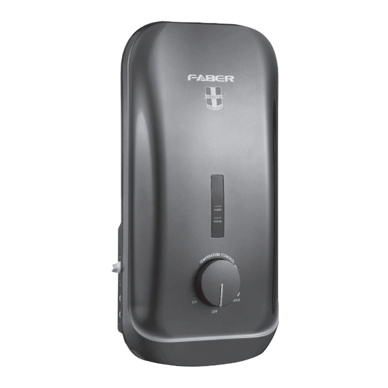
- Page 3 EXTERNAL PARTS IDENTIFICATION Power LED Heater LED Temperature Control Knob ABS Front Cover INTERNAL PARTS IDENTIFICATION ABS Heater Base Terminal Block ELCB Control Board Cable Entry Thermal Cut Out Booster Pump LED Display Board Heater Tank Booster Pump Control Knob Triac Heater Control Unit Test &...
- Page 4 SHOWER SET ACCESSORIES IDENTIFICATION 1. CHROME/ WHITE ACCESSORIES Wall Bracket Hand Shower Shower Holder G1/2 Slider Railbar Wall Bracket 150mm Flexible Hose...
- Page 5 SHOWER SET ACCESSORIES IDENTIFICATION 2. RAIN SHOWER SET Water Saver Chip Water Saver Chip Tighten the bottom screws Slide down and hook assembled diverter to mounted square bracket STEP 1 STEP 2 Do marking for the location of the lower square and upper There is two Water Saver Chips located round bracket.
-
Page 6: General Information
2. GENERAL INFORMATION INSTALLATION CAUTION: THIS APPLIANCE MUST BE EARTHED 1. All the plumbing work should be completed before proceeding to electrical wiring connection. (Table 1) 2. Installation must be carried out by a qualified electrician with close reference to the operation manual and in compliance with the local regulations. -
Page 7: Installation Procedures
3. INSTALLATION PROCEDURES 1. All the plumbing works should be completed before proceeding to electrical wiring connection. 2. INLET and OUTLET connection of the heater unit should not be reversed, with stop valve installed on INLET. (Diagram 1) 3. It is recommended that the unit should be mounted stopvalve above 1.5m or 5-feet above the floor to bottom of incoming... - Page 8 Electrical Connection a) Insert electrical cable through the rubber Restore cover grommet as shown. b) Connect the cable to the terminal block and fully tighten them as the following:- • Red or Brown........Live (L) • Black or Blue.......... Neutral (N) •...
-
Page 9: Operation Procedure
4. OPERATION PROCEDURE Switch on the main power supply, the ‘POWER’ LED would light up. Turn on the water supply at the stop valve. Turn on the Temperature Control Knob. The ‘HEATER’ LED would light up and the water temperature will be increased accordingly as the knob being turned clockwise from ‘ON’... -
Page 10: Technical Specification
6. TECHNICAL SPECIFICATION 3.6kW 240V 50/60Hz Please refer Electrical loading Table 1 6 bar ( 0.6MPa / 87psi ) 440(H) x 230(W) x 80(D) Non Pump 1.4kg Inverter Silent Pump1.9kg AC Pump 2.2kg Notes: The specification, actual product’s design and accessories parts shown are correct at the time of printing and subject to change without prior notices. - Page 11 AC PUMP (FWH SOTTILE 308AC) NON -PUMP (FWH SOTTILE 306/307)


Need help?
Do you have a question about the SOTTILE SLIM Series and is the answer not in the manual?
Questions and answers