Advertisement
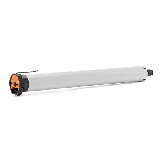
Awning drive SunTop-868
Keep these instructions in a safe place!
After installation of the motor attach these instructions
to the cable for the electrician.
Device functions:
• Commissioning of the drive using assembly cable or radio
transmitter
Delivery condition (commissioning mode)
• Setting the end positions
Important safety instructions!
Observe the following instructions.
Risk of injury due to electric shock.
The connections to the 230 V mains must be made
Warning!
by authorised specialist personnel.
Check the system (awnings) regularly for wear or
damage.
The regulations of the local energy supply company
as well as the regulations for wet and damp rooms
according to VDE 0100 must be followed when
making the connections.
Only use unmodified original elero parts.
Keep people away from the system until it is
stationary.
When working on the system (servicing, cleaning
windows etc.), always disconnect it from the mains
supply.
Intended use
• Please ensure that the radio installations are not operated in
areas of increased possible interference.
(e.g. hospitals, airports ...).
• The radio control is only permitted for devices and units with which
a functional interference in hand-held/wall-mounted transmitters
or receivers poses no danger for persons, animals or materials or
where this risk is covered by other safety appliances.
• The operator has no protection whatsoever from interferences
by other radio emitters and local terminals (e.g. also from radio
installations), that are normally used on the same frequency
range.
• Only use radio receivers with equipment and units approved by
the manufacturer.
Optimal use of the radio signal
• Do not bend the antenna.
• Do not shorten or extend the antenna.
• If reception is poor, adjust the antenna.
• Install the antenna so that it is as exposed as possible.
• The minimum distance between two radio drives must be at
least 15 cm.
Check the following before installation:
• The drive is only capable of operation as installed.
• Only perform connecting work with the power turned off.
• The blind must be attached to the winding shaft.
• The profile tube must have sufficient clearance from the motor
tube.
• Make sure there is sufficient axial play (1–2 mm)
Installation in profile tubes
Ⓐ
Push drive with relevant adapter and
limit switch crown into the profile
tube.
Lay the motor cable so that it is
protected, do not kink.
Ⓑ
Secure the counterpart support to
prevent axial movement,
e.g. screw or rivet on the idler.
Secure the drive axially in the
support!
Ⓒ
Attach the blind to the shaft!
Risk of injury due to electric shock.
Warning!
Do not drill in the area of the motor!
Installation
Observe the following installation instructions!
– The drive must be fixed in such a way that it does
not endanger personnel.
Warning!
– Before installing the drive, all lines and equip-
ment, which are not required for operation, must
be removed from the site.
– During installation, during operation and when
work is carried out on the system, the option to
separate all poles from the mains must always
exist (Hirschmann connector and Hirschmann
coupling or a two-pole switch with minimum 3 mm
contact gap or all-pole main switch).
– If the drive is controlled by a switch with OFF
pre-setting (dead man's button), the momentary
contact switch must be fitted at a height of more
than 1.50 m and separated from the moving parts.
The travel range of the systems must always be
visible during operation.
– Moving parts in a drive, which are below 2.5 m,
must be protected.
– Set torque and set operating time must meet the
requirements of the product which is driven.
– Please note the technical data on the type plate.
– Please note that with this drive (type 11 M motor)
the smallest internal tube diameter corresponds
with 47 mm.
– The drive must be installed so that it cannot get
wet.
– Do not install drives in surroundings which are at
risk of explosion or in mobile appliances
(e.g. motor vehicles).
– Keep children away from the (remote) control unit.
A
B
C
138134201_EN_0413
Advertisement
Table of Contents

Related Manuals for elero SunTop-868


Summary of Contents for elero SunTop-868
- Page 1 Do not drill in the area of the motor! as well as the regulations for wet and damp rooms according to VDE 0100 must be followed when making the connections. Only use unmodified original elero parts. Keep people away from the system until it is Installation stationary.
-
Page 2: Type Of Installation
Connection/Installation/Commissioning Remove of the motor cable plug Commissioning Note: The drive is in commissioning mode when delivered. Risk of injury due to electric shock. Upper limit stop When the motor cable plug Warning! is removed the supply line must be volt free. Lower limit stop Delivery condition Remove plug... -
Page 3: Programming The Transmitter
Programming the transmitter/ Programming further transmitters Programming the transmitter Programming procedure for other transmitters Condition: The drive is in radio mode. Programming procedure possible for max. 16 transmitters. The end positions must have been programmed. If the end positions have not been programmed, In order to program further transmitters, start with the new remove the blind from the shaft. - Page 4 End position setting Installation method 1: Upper/lower end position freely adjustable Installation method 1: Upper/lower end position freely adjustable Note: Ensure that the equipment is correctly connected. STOP Auto (Assembly cable or transmitter operation) Auto Reset Reset VarioTec VarioTec 4. Press the DOWN button again. Move the blind down until it is a short distance above the STOP desired lower end position.
- Page 5 End position setting Installation method 2: Fixed upper limit stop/lower end position freely adjustable Installation method 2: Fixed upper limit stop/lower end position freely adjustable Note: Ensure that the equipment is correctly connected. STOP Auto (Assembly cable or transmitter operation) Auto Reset Reset...
- Page 6 End position setting Installation method 3: Fixed upper and lower limit stop Installation method 3: Fixed upper and lower limit stop Note: Ensure that the equipment is correctly connected. (Assembly cable or transmitter operation) STOP Auto Auto Reset Reset VarioTec VarioTec 4.
- Page 7 End position setting Installation method 4: Upper end position freely adjustable/fixed lower limit stop Installation method 4: Upper end position freely adjustable/fixed lower limit stop Note: Ensure that the equipment is correctly connected. STOP (Assembly cable or transmitter operation) Auto Auto Reset Reset...
-
Page 8: Troubleshooting
Changing/Deleting the end positions Notes on troubleshooting Changing / Deleting the end positions using the Changing/Deleting the end positions using the radio assembly cable transmitter Mains Mains Blau (Neutralleiter) Blau (Neutralleiter) Schwarz Schwarz Braun Braun Grün-gelb Grün-gelb 1. Switch off/on mains. 1. -
Page 9: Notes On The Ec Declaration Of Conformity
EC Declaration of conformity Notes on the EC declaration of conformity elero GmbH hereby declares that the tubular drive Sun- Top-868 complies with the basic prerequisites and the other relevant provisions of the EC directives. The complete declaration of conformity can be found in the download area of our website www.elero.com/en/downloads-service/...
Need help?
Do you have a question about the SunTop-868 and is the answer not in the manual?
Questions and answers