
Related Manuals for elero LIMAline 60


Summary of Contents for elero LIMAline 60
- Page 1 LIMAline 60 Drive system Operating instructions Please take care of the operating instructions! 04/2016, TN: 2011538...
- Page 2 Translation from the original German version. All other documents in different languages are translations of the original version. Subject to change without notice. All rights reserved in the event of registrati-on of patents, working models or design patents.
-
Page 3: Table Of Contents
Table of contents Table of contents General ....................3 Information relating to the installation instructions..........3 Standards and guidelines ................. 3 Intended use ..................... 3 Foreseeable misuse ..................4 Warranty and liability ..................4 Customer service of the manufacturer ............. 5 Safety .................... - Page 4 Table of contents Accessories ..................24 Conversion gearbox ..................24 Angle gearbox 90° ..................25 Adapter vertical....................25 Adapter horizontal ..................25 Declaration of incorporation ............26 Waste disposal ................. 27 Scrapping ....................... 27 Disposal of waste electrical and electronic components ........ 27...
-
Page 5: General
General General Information relating to the installation instructions The contents are classified in accordance with the life stages of the LIMAline worm gear (hereinafter referred to as the "device"). The manufacturer reserves the right to make changes to the technical specifications stated in these installation instructions. In detail these can differ from the respective version of the device without the factual information being fundamentally changed and without los- ing their validity. The current status of the technical specifications can be requested from the manufacturer at any time. -
Page 6: Foreseeable Misuse
General If a direct or indirect hazard to personnel cannot be ruled out, additional measu- res (e.g. covers, barriers, etc.) must be taken in order to minimise the potential risk accordingly. The operator alone is liable for any damage arising from the non-intended use of the device. -
Page 7: Customer Service Of The Manufacturer
If you have not purchased the device directly from elero, please contact the manufacturer of the machine or the supplier of the device. -
Page 8: Safety
Safety Safety General safety notices and directions These installation instructions contain all the safety notices and directions that must be observed in order to avoid and prevent dangers when working with the device in the individual life cycles. Safe use of the device is guaranteed when all the specified safety notices and directions are complied with. - Page 9 Safety The following table describes the symbols used in these installation instructions for the graphic display of danger situations in connection with the symbol for the danger level. Symbol Meaning Danger due to an electrical voltage, electric shock: This symbol refers to dangers associated with electrical currents. Danger of crushing and killing people: This symbol refers to dangers due to which the entire body or individual limbs can become crushed or injured.
-
Page 10: Safety Principles
Safety Safety principles The device is built according to state-of-the-art technology and the generally accepted rules of safety and it is safe to operate. The basic safety and health requirements of the applicable laws, standards, directives and guidelines have been applied in the construction of the device. The safety of the device is con- firmed by the Declaration of Incorporation. -
Page 11: General Duties Of The Plant Operator
Safety General duties of the plant operator R The plant operator is obligated to use the device only in perfect and opera- tionally safe condition. He must ensure that, in addition to the safety notices and directions in the installation instructions, the generally accepted safety and accident prevention regulations, the specifications of DIN VDE 0100 and the provisions relating to environmental protection of the respective country of use, are heeded and complied with. -
Page 12: Safety Notices And Directions Relating To The Technical Condition
Safety Safety notices and directions relating to the technical condi- tion R The device must be checked before installation for damage and proper condition. R The plant operator is obligated to operate the device only in perfect and operationally safe condition. The technical condition must comply with the legal requirements at all times. -
Page 13: Safety Instructions Relating To Operation
Safety Safety instructions relating to operation R The operator of the device is obligated to ensure the safe and proper state of the device before the initial start of operation. R This is also necessary during operation of the device at regular intervals to be determined by the plant operator. -
Page 14: Product Description
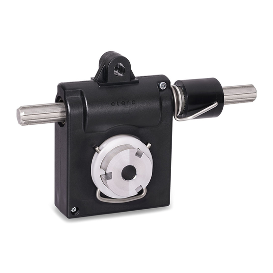
Product description Product description General The device is designed for adjusting slat systems in façade construction. Abb. 1 Components of the device Profile bushing Structural torque arm Profile shaft Housing Worm gear Worm shaft Lug with circlip Profile bush clip... -
Page 15: Technical Specifications
Product description Technical specifications All information in this section relates to an ambient temperature of 20°C. 3.2.1 Summary of the technical parameters Technical specifications LIMAline 60 Peak demand, static 60 Nm Peak demand, dynamic 16 Nm required driving torque for dynamic... -
Page 16: Information Relating To The Self-Locking Facility
Product description 3.2.2 Information relating to the self-locking facility WARNING Danger of injury through loss of the self-locking facility. Crushing and fatal injuries are possible. • Pay attention to static loads. CAUTION Possible damage to the device or customer’s machine through loss of the self- locking facility. -
Page 17: Installation
Installation Installation The information regarding electrical components refers to the attachment and connection of drive motors for the device. They are not included in the scope of delivery of the device. WARNING Danger of life-threatening injury due to faulty electrical connection. Electric shock possible. - Page 18 Installation CAUTION Damage to the device through incorrect customer assembly. • Observe the protection class. • The device must be protected from water splashing and dripping water. • It must also be protected from UV radiation, dirt and dust. CAUTION Damage to the device due to radial and/or torsional forces.
-
Page 19: Assembly Of The Device
Installation Assembly of the device The device is designed for installation in a building structure. Fasten the device only by the profile bushing and torque arm fastening elements provided for this purpose. Abb. 2 Assembly of the device Structural torque arm Building structure Structural support of the profile bushing Structural spacer rings 4.1.1 Structural support and assembly of the profile bushing The profile bushing is supported axially and radially with two flange sleeves (e.g. -
Page 20: Structural Torque Arm
Installation This significantly reduces the supplementary fine adjustment. The profile bushing is locked by the profile bush clip in the device to prevent axial displacement. The profile bushing can be removed after the profile bush clip has been pulled to the outside. To lock the profile bushing again, the slot in the profile bushing and the profile bush clip must be in the same plane. Spacer rings: The device can adjusted to the clearance of the structure by installing spacer rings on the right and left. The spacer rings are pushed onto the profile bushing as required during installation. The spacer rings have an internal diameter of 35.1 mm and an external dia- +0,2 meter of 45 mm. -
Page 21: Readjustment And Fine Adjustment
Installation A transverse hole is drilled at one end of the profile shaft. Subsequently an ad- apter is screwed to the transverse hole (adapter horizontal, TN 75128920x or adapter vertical, TN 75135910x). The drive motor is positioned after the adap- ter. It must be horizontally attached at the adapter. The vertical adapter can be attached with the drive motor. -
Page 22: Installation Dimensions
Installation Abb. 3 Readjustment and fine adjustment of the slat axis Adjustment key Worm shaft Lug with circlip The lug clip is folded outwards for readjustment and fine adjustment of the slat axis. The lug can then be moved approx. 20 mm on the profile shaft. Now the slat axis can be adjusted by rotating it with the adjustment key. Installation dimensions The clearance for the installation dimensions in the structure is min. 44 mm x 125 mm. - Page 23 Installation Abb. 4 Installation dimensions Clearance without JA drive min. 44 mm/with JA drive min. 55 mm Clearance min. 125 mm approx. 37 mm Abb. 5 Axial dimension with JA drive motor on one side and centrally positioned...
-
Page 24: Assembly Of Drive Motors
Installation Installation dimensions when using an elero drive motor of the JA series driving driving axial dimen- axial dimension Drive torque (Nm) torque (Nm) sion A (mm) A (mm) both sides one side (JA centred) (JA one side) 10,0 JA 20 dk 10,0 + 10,0 min. - Page 25 Installation Vertical installation position: If the JA drives are installed vertically the cable output must be at the top. If the cable output is at the bottom when vertically installed, lubricants may penetrate the brake, the limit switch area and the electric motor of the JA drive. This will cause faults or premature failure of the JA drives.
-
Page 26: Accessories
Accessories Accessories Conversion gearbox The drive motor can be positioned parallel to the drive train with the conversion gearbox. The gearbox has a ratio of i = 1.91. Drive torque: max. 10 Nm Output torque: max. 19 Nm Pinion: V2A Abb. 6 General view of the application of the conversion gearbox The fitting position of the conversion gearbox must be centred in the drive train. -
Page 27: Angle Gearbox 90
Accessories Angle gearbox 90° The drive motor can be positioned at 90° to the drive train with the angle gear- box (TN 75153000x). The gearbox has a ratio of i = 2. Drive torque: max. 10 Nm Output torque: max. 20 Nm Abb. 7 General view of the application of the angle gearbox Assembly: The angle gearbox is pushed onto the profile shaft and fastened to the structure with 4 internal thread M6 x 10 bolts. -
Page 28: Declaration Of Incorporation
Declaration of incorporation Declaration of incorporation The complete declaration of incorporation can be downloaded from our website: www.elero-linear.de/downloads. -
Page 29: Waste Disposal
Waste disposal Waste disposal Scrapping When scrapping the device, comply with the internationally, nationally and re- gionally specific laws and regulations valid at that point in time. Ensure that the recycling capability, dismantling capability and separation capa- bility of the materials and subassemblies as well as the environmental and health dangers are all taken into consideration for the recycling and waste dis- posal. - Page 31 GmbH Naßäckerstraße 11 07381 Pößneck Germany +49 3647 46 07-0 +49 3647 46 07-42 info@elero-linear.de www.elero-linear.com...
Need help?
Do you have a question about the LIMAline 60 and is the answer not in the manual?
Questions and answers