Table of Contents
Advertisement
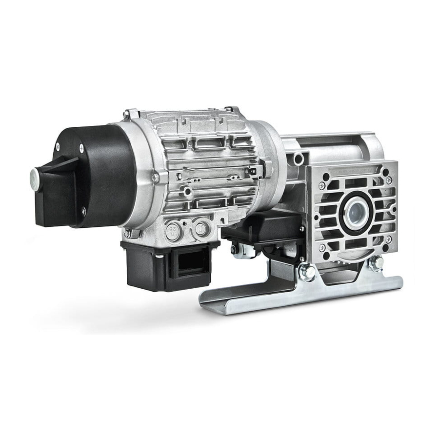
Shaft mounted rolling door drives
DFM/DFE 100, 170, 250, 350, 500 and 750
WFM/WFE 170
Assembly instructions (translation)
For the safety of persons it is important to follow these assembly instructions!
Keep the assembly instructions in a safe place!
Contents
DIN EN ISO 9001: 2008
Certificate 01 100 070016/03
Page
2-4
4
5
6
7
8
9
10
11
12
13
14
16
148074702_EN_0713
Advertisement
Table of Contents


Need help?
Do you have a question about the DFM 100 and is the answer not in the manual?
Questions and answers