Evolution FURY5-S Original Instructions Manual
Hide thumbs
Also See for FURY5-S:
- Original instructions manual (126 pages) ,
- Original instructions manual (113 pages) ,
- Original instructions manual (193 pages)

Related Manuals for Evolution FURY5-S


Summary of Contents for Evolution FURY5-S
- Page 1 FURY5-S Original Instructions Original-Anweisungen Original written in UK English Date Published: 15 / 03 / 2019...
-
Page 2: Table Of Contents
www.evolutionpowertools.com INTRODUCTION Page 3 OPERATION Page 21 Machine Specification Page 4 On/Off Safety Switch Page 21 Vibration Page 5 Raising/Lowering the Blade Page 21 Labels and Symbols Page 5 Tilting the Blade Page 22 Intended use of this Power Tool Page 6 Rip Fence Guide Page 22... -
Page 3: Introduction
You can also scan the QR code found on the A4 leaflet with a smart phone. This will enable you to validate your machine’s guarantee period via Evolution’s website by entering your details and thus ensure prompt service, if ever needed. We sincerely thank you for selecting... -
Page 4: Machine Specification
www.evolutionpowertools.com MACHINE SPECIFICATIONS MACHINE METRIC IMPERIAL Motor (UK/EU) 220-240v ~ 50/60Hz 1300 W (S1) 6.5A 1500 W (S6 40%) Table Dimensions 583 x 901mm 23 x 35-1/2” Riving Knife Thickness 1.8mm 5/64” Speed No Load 3250min 3250rpm Weight 20.14kg 44.4lbs CUTTING CAPACITY METRIC IMPERIAL... -
Page 5: Vibration
WARNING: Do not operate this machine if • The measurement and assessment of warning and/or instruction labels are missing human exposure to hand-transmitted or damaged. Contact Evolution Power Tools vibration in the workplace is given in: for replacement labels. BS EN ISO 5349-1:2001 and... -
Page 6: Intended Use Of This Power Tool
THIS POWER TOOL Volts WARNING: This product is a table saw and Amperes has been designed to be used with special Evolution blades. Only use accessories Hertz designed for use in this machine and/or Speed those recommended specifically by Evolution Power Tools Ltd. -
Page 7: Safety Precautions
www.evolutionpowertools.com SAFETY PRECAUTIONS The term “power tool” in the warnings refers to your mains-operated (corded) power tool or battery-operated (cordless) power tool. (1.14) ELECTRICAL SAFETY (2.2) 1) General Power Tool Safety Warnings This machine is fitted with the correct moulded [Work area safety] plug and mains lead for the designated market. - Page 8 www.evolutionpowertools.com current device (RCD) protected supply. [Power tool use and care]. a) Do not force the power tool. Use the Use of an RCD reduces the risk of electric shock. correct power tool for your application. The correct power tool will do the job better (2.4) 3) General Power Tool Safety Warnings and safer at a rate for which it was designed.
-
Page 9: Additional Safety Instructions
www.evolutionpowertools.com ADDITIONAL SAFETY INSTRUCTIONS identical replacement parts. This will - TABLE SAWS ensure that the safety of the power tool is maintained. 1) Guarding related warnings (2.7) HEALTH ADVICE a) Keep guards in place. Guards must be in working order and be properly mounted. WARNING: When using this machine, dust A guard that is loose, damaged, or is particles may be produced. - Page 10 www.evolutionpowertools.com function properly, the saw blade diameter your hand to slip into the saw blade. g) Do not perform any operation must match the appropriate riving knife and the body of the saw blade must be “freehand”. Always use either the rip fence or the mitre gauge to position thinner than the thickness of the riving and guide the workpiece.
- Page 11 www.evolutionpowertools.com the saw blade and the rip fence or other fixed placed under all portions of the panel object. overhanging the table top. Most frequently during kickback, the h) Use extra caution when cutting a workpiece that is twisted, knotted, workpiece is lifted from the table by the rear warped or does not have a straight portion of the saw blade and is propelled...
-
Page 12: Getting Started
www.evolutionpowertools.com GETTING STARTED be installed in an area that provides UNPACKING enough room to easily handle the size of your workpiece. Cramped, dark areas, and uneven slippery floors invite Caution: This packaging contains sharp accidents. objects. Take care when unpacking. d) Frequently clean and remove sawdust Remove the machine, together with the from under the saw table and/or the... -
Page 13: Items Supplied
1 Bag Riving Knife (4.3) ADDITIONAL ACCESSORIES In addition to the standard items supplied with this machine the following accessories are also available from the Evolution online shop at www.evolutionpowertools.com or from your local retailer. (4.4) Description Part No Multi-Material... -
Page 14: Machine Overview
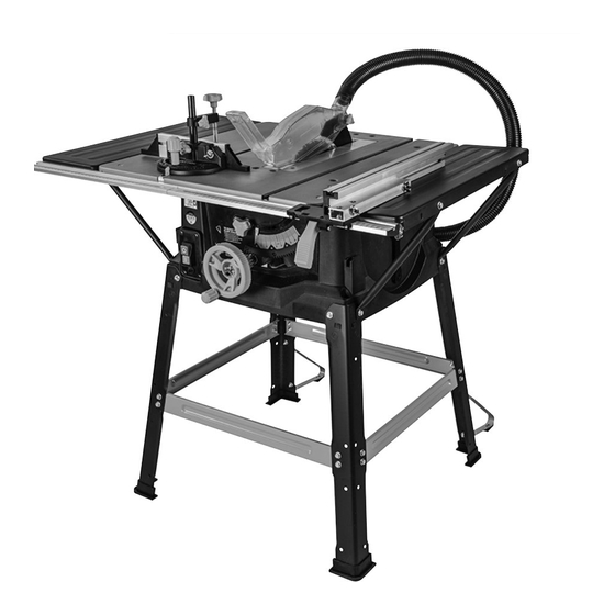
www.evolutionpowertools.com MACHINE OVERVIEW 1. ON/OFF SWITCH 9. PUSH STICK 2. RIVING KNIFE 10. RIP FENCE 3. BLADE GUARD 11. REAR CANTILEVER BRACES 4. BLADE 12. ANTI-BOUNCE DEVICE 5. BEVEL LOCKING KNOB 13. SLIDING MITRE FENCE 6. RISE AND FALL/BEVEL ADJUSTMENT 14. -
Page 15: What's In The Box
www.evolutionpowertools.com WHAT’S IN THE BOX A. BLACK CORNER LEGS (STAMPED A) x 4 K. MITRE GAUGE B. CROSS-BRACES (STAMPED B) L. FENCE RAIL 2 pieces C. CROSS-BRACES (STAMPED C) M. FENCE RAIL JOINING TONGUE D. REAR CANTILEVER BRACES N. HEX HEADED SCREW x 28 E. -
Page 16: Assembly
www.evolutionpowertools.com ASSEMBLY Note: This process can be considerably aided by studying the images of an assembled machine as found on the machine overview page. THE STAND Four corner legs (A) (stamped A) and four cross-braces (B+C) comprise the main stand components. Fig. -
Page 17: Attaching The Table Extensions
www.evolutionpowertools.com • Attach the side cross-braces (C) to the corner legs (Fig. 5) in the same manner as the front and rear cross-braces were attached. • Push fit the rubber feet (E) onto the bottom of each leg. Note: The machine can now be lifted from the work-surface/workbench. -
Page 18: The Fence Rail
www.evolutionpowertools.com • Insert the machine screw through the end of the support strut and refit the machine screw to the machines main body. (Fig. 9) Use a straight edge or similar placed across the table and the extension panel to check the alignment. The extension panels should be exactly level with and flush to the main table of the machine. -
Page 19: Checking/Adjusting The Rip Fence
www.evolutionpowertools.com • Loosen slightly the seven coach bolts (P) which hold the fence rail to the machine. • Gently move the fence rail to the right or left until the ‘0’ position on the scale coincides with the datum line in the magnifier. -
Page 20: Top Blade Guard
www.evolutionpowertools.com thin walled metal tube etc). At other times safely store the device off the machine. The pillar of the anti-bounce device fits into the socket in the mitre gauge base, and is held in place by a thumb screw. (Fig 17) TOP BLADE GUARD The top blade guard (H) (sometimes referred to as a crown guard) must always be fitted to the machines riving knife. -
Page 21: Operation
(Fig. 22) Note: The ‘free’ port of the 2 way connector can be used to attach a workshop dust extraction machine to this Evolution machine. If such a machine is connected to this Table Saw follow the Instructions provided by the supplier/manufacturer of the dust extraction equipment. -
Page 22: Tilting The Blade
www.evolutionpowertools.com cog engages with a curved toothed rack incorporated into the machines main body. This allows the hand-wheel to be used to adjust the tilt/bevel angle of the blade To raise or lower the blade: • Ensure that the hand-wheel is in the ‘normal’ (outer) position. •... -
Page 23: Dual Read Scale
www.evolutionpowertools.com Note: We recommend that normally the rip fence faceplate be adjusted so that the rear of the faceplate guide is ‘in line’ with the rear of the blade where it emerges from the table. (Fig. 28B) Note: If the rip fence is used on the LH (left hand) side of the blade, the aluminium faceplate will have to be repositioned to the RH (right hand) side of the plastic carrier. -
Page 24: Anti-Bounce Device
www.evolutionpowertools.com Turn the vertical handle counter-clockwise to unlock the mitre gauge, and adjust to the required angle. Turn the handle clockwise to lock the mitre gauge at the chosen angle. Note: The extruded aluminium faceplate of the mitre gauge should be adjusted so that it passes close to, but does not touch the blade or blade guard. -
Page 25: Cross-Cutting
www.evolutionpowertools.com WARNING: This machine is not suitable for cutting rebates or stopped grooves. A workshop dust extraction machine can be connected to the extraction port found at the rear of the machine if required. CROSS-CUTTING Set the mitre gauge to 0˚ and tighten using the vertical handle. Position in the desired ‘T’... -
Page 26: Rip Cutting
www.evolutionpowertools.com • Adjust and align the back of the rip fence faceplate with the front of the saw blade. (Fig. 39) This setting will afford clearance for the material as it passes through the saw blade. It will allow the cut material to move sideways away from the saw blade, with little risk of any binding or kickback occurring. -
Page 27: Bevel Ripping
www.evolutionpowertools.com BEVEL RIPPING Bevel ripping is cutting along the length of a work-piece with the saw blade tilted at an angle. When bevel ripping material 150mm or narrower use the rip fence on the RH side of the blade only. (Fig 42) MAINTENANCE WARNING: Ensure that the machine is disconnected from the Fig. -
Page 28: Riving Knife
Fig. 46 Note: Use only a genuine Evolution riving knife, as this is a dedicated component for this machine. Non genuine parts could be dangerous. If in any doubt, please contact the helpline. -
Page 29: Declaration Of
In accordance with EN ISO 17050-1:2004 The manufacturer of the product covered by this Declaration is: UK: Evolution Power Tools Ltd. Venture One, Longacre Close, Holbrook Industrial Estate, Sheffield, S20 3FR. FR: Evolution Power Tools SAS. 61 Avenue Lafontaine, 33560, Carbon-Blanc, Bordeaux, France. - Page 30 www.evolutionpowertools.com EINFÜHRUNG Seite 31 BETRIEB Seite 49 Garantie Seite 31 Ein-/Aus-Sicherheitsschalter Seite 49 Maschinenspezifikation Seite 32 Heben/Senken des Sägeblatts Seite 49 Vibration Seite 33 Kippen des Sägeblatts Seite 50 Aufkleber und Symbole Seite 33 Längsanschlagführung Seite 50 Bestimmungsgemäße Seite 34 Gehrungslehre Seite 51 Verwendung dieses...
-
Page 31: Einführung
Lieferanten. www.evolutionpowertools.com Glückwunsch zum Kauf einer Maschine (1.4) von Evolution Power Tools. Bitte füllen Sie Ihre Produktregistrierung online wie es in der A4- Broschüre zur Online-Garantieregistrierung erklärt ist, die dieser Maschine beiliegt. Sie können auch den QR-Code, der sich auf der A4-Broschüre befindet, mit einem Smartphone scannen. -
Page 32: Maschinenspezifikation
www.evolutionpowertools.com MASCHINENSPEZIFIKATIONEN MASCHINE METRISCH BRITISCHE EINHEITEN Moteur (UK/EU) 220-240v ~ 50/60Hz 1300 W (S1) 6,5 A 1500 W (S6 40%) Tischabmessungen 583 x 901mm 23 x 35-1/2” Spaltkeildicke 1.8 mm 5/64” Leerlaufdrehzahl 3250 min 3250 rpm Gewicht 20.14kg 44.4lbs SCHNITTLEISTUNG METRISCH BRITISCHE EINHEITEN... -
Page 33: Vibration
Anwender dieser Maschine sollten den fehlen oder beschädigt sind. Für Ersatzaufkleber Zustand ihrer Hände und Finger genau wenden Sie sich bitte an Evolution Power Tools. überwachen. Suchen Sie sofort einen Arzt auf, wenn eines der Symptome auftaucht. Hinweis: Alle oder einige der Symbole auf der nächsten Seite können im Handbuch oder auf... -
Page 34: Bestimmungsgemäße
Ampere entwickelt. Verwenden Sie nur Zubehör, das für die Verwendung in dieser Maschine entwickelt Hertz wurde und/oder solches, das speziell dafür empfohlen wird von Evolution Power Tools Drehzahl Ltd. Wechselstrom Wenn diese Maschine mit einem geeigneten Sägeblatt ausgerüstet ist, kann diese Maschine... -
Page 35: Elektrische Sicherheit
www.evolutionpowertools.com Gase oder Stäube befinden. Kundendienstvertreter erhältlich sind. Elektrowerkzeuge erzeugen Funken, die den Staub oder die Dämpfe VERWENDUNG IM FREIEN entzünden können. (1.15) c) Halten Sie Kinder und andere WARNUNG: Bei einer Verwendung im Freien sollte Personen während der Benutzung eines dieses Werkzeug zu Ihrem Schutz nicht Regen Elektrowerkzeugs fern. - Page 36 www.evolutionpowertools.com c) Trennen Sie das Elektrowerkzeug Alkohol oder Medikamenten stehen. von der Steckdose bzw. nehmen Sie den Moment der Unachtsamkeit beim Gebrauch eines Elektrowerkzeugs kann zu schweren Akku aus dem Elektrowerkzeug, bevor Sie Verletzungen führen. Geräteeinstellungen vornehmen, Zubehörteile b)Tragen Sie persönliche Schutzausrüstung. wechseln oder das Elektrowerkzeug verstauen.
-
Page 37: Zusätzliche Sicherheitshinweise
www.evolutionpowertools.com c) Befestigen Sie die Schutzvorrichtung Farbe auf Bleibasis sollte nur von einem Fachmann unmittelbar nach Abschluss des Schnitts entfernt werden uns Sie sollten nicht versuchen, erneut (wie Falz-, Nut- oder Neuschnitte), sie selbst zu entfernen. Sobald sich der Staub auf für welche die Vorrichtung, der Spaltkeil Oberflächen abgesetzt hat, kann ein Kontakt und/oder die Rückschlagsicherung... - Page 38 www.evolutionpowertools.com Längenanschlag beim Querschneiden mit k) Entfernen Sie keine Stücke von der Gehrungsanzeige. Die gleichzeitige Schnittmaterial, während die Säge läuft. Führung des Werkstücks mit dem Das Material kann zwischen dem Anschlag oder Parallelanschlag und der Gehrungsanzeige innerhalb des Sägeblattschutzes eingeschlossen erhöht die Wahrscheinlichkeit von sein, sodass das Sägeblatt Ihre Finger in das Sägeblattverklemmungen und des...
- Page 39 www.evolutionpowertools.com wenn die Maschine unbeaufsichtigt bleibt. gegen das Sägeblatt und führt zu Ausschlagen. e) Verwenden Sie einen Druckkamm, um das Durch Vorsichtsmaßnahmen können Unfälle Werkstück am Tisch entlangzuführen, vermieden werden. und einen Anschlag für Teilschnitte b) Lassen Sie die Tischsäge niemals wie Falz-, Nut- oder Neuschnitte.
-
Page 40: Erste Schritte
1 Beutel mente Assorted fixings 1 Bag Spaltkeil (4.3) WEITERES ZUBEHÖR Zusätzlich zu den mit dieser Maschine mitgelieferten Standardpositionen sind auch folgende Zubehörteile im Evolution Online-Shop unter www.evolutionpowertools.com oder von Ihrem Händler vor Ort erhältlich (4.4) Beschreibung Teile-Nr. Vielzwecksägeblatt FURYBLADE255MULTI Holzsägeblatt... -
Page 41: Maschinenübersicht
www.evolutionpowertools.com MASCHINENÜBERSICHT 1. EIN-/AUS-SCHALTER 10. LÄNGSANSCHLAG 2. SPALTKEIL 11. HINTERE KONSOLENKLEMMEN 3. SÄGEBLATTSCHUTZ 12. ANTIPRELLVORRICHTUNG 4. SÄGEBLATT 13. SCHLITTENGEHRUNGSLEHRE 5. NEIGUNGS-BEFESTIGUNGSGRIFF 14. ENTSTAUBUNGSANSCHLUSS AUF UND AB-/ 15. ENTSTAUBUNGSSCHLAUCH NEIGUNGSEINSTELLUNGS-HANDRAD 16. HINTERER ENTSTAUBUNGSANSCHLUSS 7. LÄNGSANSCHLAG-SKALENLUPE 17. SCHLÜSSEL FÜR SÄGEBLATTWECHSEL LÄNGSANSCHLAG-BEFESTIGUNGSGRIFF 9. HANDGRIFF... -
Page 42: Verpackungsinhalt
www.evolutionpowertools.com WHAT’S IN THE BOX A. SCHWARZE ECKFÜSSE K. GEHRUNGSLEHRE (MIT PRÄGUNG A) B. QUERSTREBEN L. ANSCHLAGSCHIENE 2 Stück (MIT PRÄGUNG B) C. QUERSTREBEN (MIT PRÄGUNG C) M. ANSCHLAGSCHIENEN- D. HINTERE KONSOLENKLEMMEN VERBINDUNGSZUNGE E. GUMMIFÜSSE N. SECHSKANTSCHRAUBE x 28 F. SEITLICHE O. -
Page 43: Montage
www.evolutionpowertools.com MONTAGE Hinweis: Für diesen Vorgang ist es sehr hilfreich, sich die Bilder einer montierten Maschine wie auf der Übersichtsseite der Maschine genau anzusehen. DAS GESTELL Vier Eckfüße (A) (mit Prägung A) und vier Querstreben (B+C) bilden die Hauptkomponenten des Gestells. Abb. -
Page 44: Montieren Der
www.evolutionpowertools.com Ziehen Sie zu diesem Zeitpunkt die Schrauben wieder nur handfest an. • Befestigen Sie die seitlichen Querstreben (C) an den Eckfüßen (Abb. 5) genauso wie die vorderen und hinteren Querstreben angebracht wurden. • Drücken Sie die Gummifüße (E) auf die Unterseite der einzelnen Schenkel. -
Page 45: Die Anschlagschiene
www.evolutionpowertools.com • Entfernen Sie vorsichtig die entsprechende Maschinenschraube oben aus dem Eckfuß. • Setzen Sie die Maschinenschraube durch das Ende der Stützstrebe ein und befestigen Sie die Maschinenschraube wieder am Maschinenhauptteil. (Abb. 9) Verwenden Sie ein Lineal oder ähnliches über den Tisch und die Verlängerungsplatte, um die Ausrichtung zu prüfen. -
Page 46: Prüfen/Einstellen Des
www.evolutionpowertools.com • Positionieren Sie den Längsanschlag (J) in der Anschlagschiene rechts vom Sägeblatt. Heben Sie das Sägeblatt an (siehe HEBEN/SENKEN DES • SÄGEBLATTS auf Seite 49). • Schieben Sie den Längsanschlag entlang der Anschlagschiene bis er am Angehobenen Sägeblatt anliegt. •... -
Page 47: Schlittengehrungslehre
www.evolutionpowertools.com Winkelmesserfuß der Schlittengehrungslehre durch zwei Maschinenschrauben und Flügelmuttern gehalten. Die Antiprellvorrichtung (I) kann im Sockel des Fußes der Schlittengehrungslehre angebracht werden. (Abb. 15) Ein Drehen des Verriegelungsgriffs gegen den Uhrzeigersinn (Abb. 16) ermöglicht die Einstellung des Winkels der Gehrungslehre. Verwenden Sie die Skala des Winkelmessers und den Zeiger und stellen Sie die Lehre auf den gewünschten Winkel ein. - Page 48 Rückseite des Hauptteils der Maschine an. (Abb. 22) Hinweis: Der ‚freie‘ Anschluss des T-Stücks kann zum Anschluss eines Werkstatt-Staubabsauggeräts an diese Maschine von Evolution verwendet werden. Wenn so ein Gerät an diese Tischsäge angeschlossen ist, befolgen Sie die Anweisungen des Lieferanten/Herstellers des Staubabsauggeräts.
-
Page 49: Betrieb
www.evolutionpowertools.com BETRIEB EIN-/AUS-SICHERHEITSSCHALTER WARNUNG: Stellen Sie vor Betätigung des Schalters sicher, dass der Sägeblattschutz richtig montiert ist und einwandfrei funktioniert. • Drücken Sie die Taste ‚ON‘ zum Starten der Maschine. • Drücken Sie die Taste ‚OFF‘ zum Stoppen der Maschine. Abb. -
Page 50: Kippen Des Sägeblatts
www.evolutionpowertools.com Zum Kippen des Sägeblatts: • Lösen Sie den Arretiergriff zum Kippen (Abb. 26) • Drücken Sie das Zweifunktions-Handrad hinein und stellen Sie sicher, dass der Zahn in die Zahnstange einrastet. • Drehen Sie das Handrad, um das Sägeblatt zu kippen. Hinweis: Eine Winkelmesserskala und ein Zeiger (Abb. -
Page 51: Gehrungslehre
www.evolutionpowertools.com Kehren Sie zur originalen Konfiguration zurück, wenn sich der Längsanschlag in der normalen (rechten) Betriebsposition befindet. Hinweis: Wenn die Maschine nicht in Gebrauch ist, verfügt der Parallelanschlag über einen speziellen Stauraum auf der linken Seite des Maschinengehäuses (Abb. 29). Lösen Sie die Flügelmuttern und schieben Sie den Parallelanschlaggrund in die Mitte der Frontplatte des Parallelanschlags und sichern Sie ihn. -
Page 52: Antiprellvorrichtung
www.evolutionpowertools.com WARNUNG: Führen sie mit der von der Stromversorgung getrennten Maschine einen ‚Trockenlauf‘ aus, um sicherzustellen, dass die Gehrungslehre wirklich am Sägeblatt und Sägeblattschutz ohne Berührung vorbei gleitet. ANTIPRELLVORRICHTUNG Hinweis: Beim Schneiden von dünnem Blech oder ähnlichem kann die Antiprellvorrichtung hilfreich verwendet werden. -
Page 53: Querschneiden Mit Gehrung
www.evolutionpowertools.com QUERSCHNEIDEN Stellen Sie die Gehrungslehre auf 0° und arretieren Sie sie mit dem vertikalen Griff. Positionieren Sie sie in der gewünschten ‘T’-Nut und stellen Sie die Anschlagplatte der Gehrungslehre wie zuvor beschrieben ein. Halten Sie das zu schneidende Material gegen die Anschlagplatte der Gehrungslehre (Abb.36). -
Page 54: Längsschneiden
www.evolutionpowertools.com • Stellen Sie die Anschlagplatte des Längsanschlags ein und richten Sie sie mit der Vorderseite des Sägeblatts aus. (Abb. 39) Diese Einstellung erfordert einen Freiraum für das Material beim Passieren des Sägeblatts. Er ermöglicht, dass sich das geschnittene Material zur Seite weg vom Sägeblatt bewegt mit der geringen Gefahr, dass ein Fressen oder Rückschlagen auftreten kann. -
Page 55: Schräg-Längsschneiden
www.evolutionpowertools.com Wenn die Breite beim Längsschneiden mehr als 300 mm beträgt und vorsichtig vorgegangen wird, können beide Hände zum Führen/Zuführen des Materials durch die Säge verwendet werden Die linke Hand des Bedieners befindet sich dabei links vom Sägeblatt. Die rechte Hand des Bedieners befindet sich nahe am Längsanschlag rechts vom Sägeblatt. -
Page 56: Reinigung
Techniker durch ein originales Ersatzteil ersetzen, wenn er verschlissen oder beschädigt ist. Hinweis: Verwenden Sie nur einen originalen Evolution Spaltkeil da dieser ein für diese Maschine zweckbestimmtes Bauteil ist. Nicht originale Teile können gefährlich sein. Kontaktieren Sie die Helpline wenn... -
Page 57: Handgriff
Hinweis: Wenn der Handgriff beschädigt wird, ist er zu Abb. 47 ersetzen. Wenn der Bediener seinen eigenen Handgriff anfertigt, empfehlen wir, dass er sich ein Beispiel am mitgelieferten nimmt. Ersatzhandgriffe sind erhältlich von Evolution Power Tools. (6.4) UMWELTSCHUTZ Elektroabfälle sollten nicht mit dem normalen Hausmüll entsorgt werden. -
Page 58: Konformitätserklärung
EN ISO 17050-1:2004 Der Hersteller des von dieser Erklärung behandelten Produkts ist: UK: Evolution Power Tools Ltd. Venture One, Longacre Close, Holbrook Industrial Estate, Sheffield, S20 3FR. FR: Evolution Power Tools SAS. 61 Avenue Lafontaine, 33560, Carbon-Blanc, Bordeaux, France. - Page 59 www.evolutionpowertools.com NOTES...
- Page 60 Evolution Power Tools Ltd Evolution Power Tools LLC Evolution Power Tools SAS Venture One 8363 Research Drive 61 Avenue Lafontaine Longacre Close Davenport 33560 Holbrook Industrial Estate Iowa Carbon-Blanc Sheffield 52806 Bordeaux S20 3FR +44 (0)114 251 1022 833-MULTI-SAW + 33 (0)5 57 30 61 89...
Need help?
Do you have a question about the FURY5-S and is the answer not in the manual?
Questions and answers