Table of Contents
Advertisement
Quick Links
Advertisement
Table of Contents

Related Manuals for Siemens Simotics SD 1LE7


Summary of Contents for Siemens Simotics SD 1LE7
-
Page 3: Safety Notes
5 safety rules 1. Disconnect the system. Also disconnect the auxiliary circuits, for example, anti-condensation heating. 2. Secure against reconnection. 3. Verify absence of operating voltage. © Siemens AG 2016 - 2018. All rights reserved A5E36065207, 04/2018... -
Page 4: Qualified Personnel
4. Ground and short-circuit. 5. Provide protection against adjacent live parts. To energize the system, apply the measures in reverse order. Qualified personnel All work at the machine must be carried out by qualified personnel only. For the purpose of this documentation, qualified personnel is taken to mean people who fulfill the following requirements: ●... -
Page 5: Intended Use
CAUTION Hazardous substances Chemical substances required for the setup, operation and maintenance of machines can present a health risk. Read the information in these operating instructions and the product information supplied by the manufacturer. • Observe the relevant safety regulations and wear the personal protective equipment specified. •... -
Page 6: Machine Design
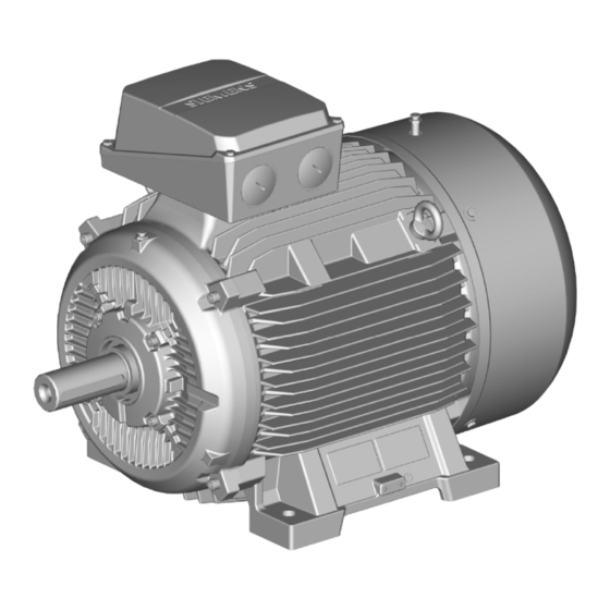
3.1.2 CE marking Use of machines without CE marking Machines without CE marking are intended for operation outside the European Economic Area (EEA). Do not use any machines without a CE marking in the EEA! Design 3.2.1 Machine design Machines of this series are low-voltage three-phase induction or reluctance-synchronous machines with a cylindrical shaft end and keyway. -
Page 7: Types Of Construction/Method Of Installation
3.2.4 Bearings In order to support the machine shaft and maintain its position in the non-moving part of the machine, only 2 rolling bearings are used. One rolling bearing performs the function of a location bearing that transfers axial and radial forces from the rotating machine shaft to the non-moving part of the machine. -
Page 8: Preparing For Use
Basic type of construction Diagram Other methods of installation Diagram code IM B5 (IM 3001) IM V1 (IM 3011) IM V3 (IM 3031) Basic type of construction Diagram Other methods of installation Diagram code IM B14 (IM 3601) IM V18 (IM 3611) IM V19 (IM 3631) Basic type of construction Diagram... -
Page 9: Observing The Operating Mode
The drive systems are put together on an individual basis. When you take receipt of the delivery, please check immediately whether the items delivered are in accordance with the accompanying documents. Siemens will not accept any claims relating to items missing from the delivery and which are submitted at a later date. - Page 10 ● When using 2-cable lifting equipment, ensure that the maximum angle of inclination is ≤45° according to ISO 3266 (DIN 580). ● Align the eyebolts so that the cables used for lifting are aligned with the planes of the eyebolts. Toppling over or slipping of the motor The motor can slide or topple over if it is not correctly lifted or transported.
-
Page 11: Electromagnetic Compatibility
Storing indoors The storage rooms must provide protection against extreme weather conditions. They must be dry, free from dust, frost and vibration and well ventilated. Bare metal surfaces For transport, the bare surfaces (shaft ends, flange surfaces, centering edges) should be coated with an anti-corrosion agent which will last for a limited amount of time (<6 months). -
Page 12: Parameterizing The Converter
Converter operation 4.6.1 Parameterizing the converter ● If the design of the motor requires connection to a particular converter type, the rating plate will contain corresponding additional information. ● Correctly parameterize the converter. Parameterizing data can be taken from the machine rating plates. You can find parameter data here: –... -
Page 13: Insulated Bearings When Operated With A Converter
● If the cable shield is connected as described, then it ensures the specified equipotential bonding between the motor enclosure and converter. A separate RF equipotential bonding conductor is then not necessary. Concentric copper or aluminum shield Steel armor ● If the cable shield is not connected due to special secondary conditions, or not adequately connected, then the specified equipotential bonding is not provided. -
Page 14: Preparing For Installation
Tandem operation If you connect two motors in series in "tandem operation", install an insulated coupling between the motors. ① ④ Driving machine Insulated bearings ② ⑤ Motor Insulated tachometer fitting ③ ⑥ Coupling Insulated coupling Figure 4-2 Schematic representation of a tandem drive NOTICE Bearing damage Bearing currents can flow if the coupling between the motors of the tandem drive is not insulated. -
Page 15: Insulation Resistance
NOTICE Damage to the motor To avoid material damage, before commissioning, check whether the correct direction of rotation of the machine has been set on the customer side, e.g. by decoupling from the driven load. 5.2.1 Insulation resistance Measuring the insulation resistance provides information about the condition of the machine. It is therefore important to check the insulation resistance at the following times: ●... -
Page 16: Machine Installation
Limit values for the stator winding insulation resistance The following table specifies the measuring voltage and limit values for the insulation resistance. These values correspond to recommendations in IS 7816. Table 5-1 Stator winding insulation resistance at 40 °C meas MΩ... -
Page 17: Ensure Adequate Cooling
● For vertical installation, use all of the eyebolts provided and when necessary, hoisting straps (DIN EN 1492-1) and/or lashing straps (DIN EN 12195-2) to stabilize the position of the motor. ● Prevent foreign bodies from falling into the fan cover. For vertical machine installation with the shaft end facing downwards, attach a protective canopy. - Page 18 5.3.3 Balancing The rotor is dynamically balanced. For shaft extensions with feather keys, the balancing type is specified using the following coding on the face of the drive end of the shaft: ● "H" means balancing with a half feather key (standard) ●...
-
Page 19: Measures For Alignment And Mounting
● Precisely align the machine when couplings are used. ● Ensure that the mounting surfaces are clean and free of any dirt. ● Remove any anti-corrosion protection using white spirit. ● Avoid installation-related resonances with the rotating frequency and twice the line frequency. ●... -
Page 20: Electrical Connection
5.4.2 Machine frame mounting feet (special design) For terminal boxes mounted at the NDE (option H08), dimension C can deviate from IS1231. For motors with double or triple holes at the NDE, maintain the foot mounting dimensions as specified in standard IS1231. Electrical connection Observe the following when carrying out any work on the machine: ●... -
Page 21: Terminal Box
Terminal box DANGER Hazardous voltage Electric motors have high voltages. When incorrectly handled, this can result in death or severe injury. Switch off the machine so that it is in a no-voltage condition before you open the terminal box. NOTICE Damage to the terminal box If you incorrectly carry out work on or in the terminal box, this can result in material damage. -
Page 22: Cable Glands
6.3.2 Cable glands Note Avoid damaging the cable jacket. Adapt the tightening torques to the cable jacket materials. You should refer to the table in order to find the correct tightening torque for any metal and plastic cable glands that are to be mounted directly on the machine, as well as for any other screw-type connections (such as adapters). -
Page 23: Final Checks
Table 6-5 Minimum cross-sectional area of grounding conductor Minimum cross-section of the phase conductor for installa- Minimum cross-section of the associated grounding connec- tion tion [mm²] [mm²] S ≤ 25 25 < S ≤ 50 S > 50 0.5 S Internal ground terminal When making connections, ensure the following: ●... -
Page 24: Setpoint Values For Monitoring The Bearing Temperature
Commissioning Observe the following when carrying out any work on the machine: ● Comply with the general safety instructions (Page 1) ● Comply with the applicable national and sector-specific regulations. ● When using the machine within the European Union, comply with the specifications laid down in EN 50110-1 regarding safe operation of electrical equipment. -
Page 25: Measures Before Start-Up
Measures before start-up NOTICE Damage to the machine In order to avoid material damage, check the following points before commissioning the motor: Using appropriate measures, check whether the correct direction of rotation of the motor has been set by the customer, •... -
Page 26: Operation
Operation Observe the following when carrying out any work on the machine: ● Comply with the general safety instructions (Page 1) ● Comply with the applicable national and sector-specific regulations. ● When using the machine within the European Union, comply with the specifications laid down in EN 50110-1 regarding safe operation of electrical equipment. - Page 27 Switching on the machine with anti-condensation heating (optional) CAUTION Machine overheating Minor injury or material damage can occur if you do not observe the following: If available, switch off the anti-condensation heating each time before switching on. • CAUTION Risk of injury when touching the fan There is a risk of injury at machines equipped with a fan cover (e.g.
-
Page 28: Safety Instructions For Inspection And Maintenance
8.1.2 Avoidance of damage to rolling bearings during stoppages Extended stoppages at the identical or almost identical resting position of the rotor in the rolling bearings can result in damage, such as brinelling or corrosion. ● During stoppages, regularly start up the machine for a brief period once a month. As a minimum, turn the rotor several times. - Page 29 WARNING Machine damage If the machine is not maintained it can suffer damage. This can cause faults which can result in eventual or immediate death, serious injury or material damage. Perform regular maintenance on the machine. CAUTION Dust disturbances when working with compressed air When cleaning with compressed air, dust, metal chips, or cleaning agents can be whirled up.
-
Page 30: Drain Condensate
– Regreasing should be carried out when the motor is running (max. 3600 rpm). The bearing temperature can rise significantly at first, and then drops to the normal value again when the excess grease is displaced out of the bearing. WARNING Rotor can fall out If the machine is in a vertical position, the rotor can fall out while work is being performed on the locating bearing. -
Page 31: Rolling Bearings
Repair Observe the following when carrying out any work on the machine: ● Comply with the general safety instructions (Page 1) ● Comply with the applicable national and sector-specific regulations. ● When using the machine within the European Union, comply with the specifications laid down in EN 50110-1 regarding safe operation of electrical equipment. - Page 32 Note Special operating conditions The operating hours are reduced, e.g. When machines are vertically mounted. • High vibration and surge loads • Frequent reversing operation • Higher ambient temperatures. • High speeds etc. • ① Heat up 80 ... 100 °C Sealing the bearings Note the following details: ●...
- Page 33 Motor types Shaft height 1LE7 4.5 ±0.6 Standard design 80 ... 112 6 ±0.8 Special design 132 ... 160 7 ±1 9.3.2 NOTICE Destruction of the fan Material damage can occur by forcefully removing the fan from the shaft. Take care not to damage the snapping mechanisms on fans that are equipped with these. Plastic fan ●...
-
Page 34: Spare Parts
Spare parts 10.1 Part lists Part Description 1.40 End shield 1.43 Shaft sealing ring 1.44 Bearing cover 1.46 Cover ring 1.49 Bolt 1.58 Spring washer 1.60 Rolling bearing 1.63 T plugs 1.65 Grease nipple 1.70 Shim (SH 80) 3.38 Featherkey 4.04 Eyebolt (SH 180...315) 4.31... -
Page 35: Exploded Drawing
10.2 Exploded drawing Size 71...90 1LE7 A5E36065207, 04/2018... - Page 36 Size 100...132 1LE7 A5E36065207, 04/2018...
- Page 37 Size 160...225 1LE7 A5E36065207, 04/2018...
- Page 38 Size 250...315 1LE7 A5E36065207, 04/2018...
-
Page 39: Preparing For Disassembly
Disposal Protecting the environment and preserving its resources are corporate goals of the highest priority for us. Our worldwide environmental management system to ISO 14001 ensures compliance with legislation and sets high standards in this regard. Environmentally friendly design, technical safety and health protection are always firm goals even at the product development stage. -
Page 40: Service And Support
● The foil used for water-proof packaging is an aluminum composite foil. It can be recycled thermally. Dirty foil must be disposed of via waste incineration. Service & support Siemens Service Center (Kalwa) Log an online service request at: www.siemens.co.in/industry-services-srf For direct access to our technical experts contact: ● Online Support: http://www.siemens.com/automation/service&support (http://www.siemens.com/automation/service&support) ●... -
Page 41: Technical Data And Drawings
Technical data and drawings Terminal box dimensions Shaft Terminal height Cable entry 71 ... 90 TB1E04 1 x M16 x 1.5 1 x M25 x 1.5 100 ... TB1F04 80.5 82.5 2 x M32 x 1.5 TB1H04 80.5 82.5 2 x M32 x 1.5 160 ... - Page 42 Arrangement of the auxiliary terminal box ① Main terminal box ② Auxiliary terminal box, type II ③ Auxiliary terminal box, type I Siemens AG Division Process Industries and Drives Postfach 48 48 90026 NÜRNBERG GERMANY 1LE7 1LE7 A5E36065207, 04/2018 A5E36065207, 04/2018...
Need help?
Do you have a question about the Simotics SD 1LE7 and is the answer not in the manual?
Questions and answers