Advertisement
Quick Links
This Operation Manual covers safety, camera functions, installation and the
correct operating procedure for the W-01CDB3. First, we ask you to read
this Operation Manual thoroughly, then install and operate the W-01CDB3
as advised. In addition, for future reference, we also advise safekeeping of
this manual.
Please contact the distributor or dealer from which the W-01CDB3 was
purchased, if you do not understand the installation, operation or safety
instructions laid out in this manual. Not understanding the contents of the
Operation Manual sufficiently may cause damage to the camera.
Guide to the Safety Symbols
The meanings of the symbols used in this operation manual are:
When you do not adhere to or take notice of the "Danger"
Danger
sign, it may lead to serious accident such as death or injury
caused by fire or electric shock.
When you do not adhere to or take notice of the "Warning"
Warning
sign, it may cause severe damage such as a physical injury.
When you do not adhere to or take notice of the "Caution"
Caution
sign, it may incur injury and cause damage to peripheral objects
in the immediate surroundings.
Cautions for Safety
The W-01CDB3 is designed to be used safely; however, it may lead to
physical accident caused by fire and electric shock if not used correctly.
Therefore, please keep and read the"Cautions for safety"for protection
against accidents.
• Do not disassemble and/or modify the W-01CDB3.
Danger
• Do not operate the W-01CDB3 with wet hands.
• Use only the AD901 or equivalent power adaptor for the
Warning
W-01CDB3.
The recommended voltage is DC+12V±10%
• Do not expose the W-01CDB3 to wetness or high moisture
conditions.
The
W-01CDB3
is designed and approved for indoor use
only. The
W-01CDB3
the location of the camera is outdoors or in an outdoor like
environment, we recommend that you use an outdoor camera
housing.
• Protect the W-01CDB3 from condensation.
W-01CDB3
Keep the
operation.
• Should the camera not work properly, switch off the power
immediately. Then, check the camera according to the
"Trouble Shooting"section.
• Avoid the striking of hard objects or dropping the
Caution
W-01CDB3.
The
W-01CDB3
uses high quality electrical parts and
precision components.
• Do not connect any power supply directly to the video out
terminal of the unit.
Do not connect the
video/power single transmission terminal. The
is not designed for use with this type of equipment. We also
advise you to read the operation manual of the monitor you
plan to use before any connections are made.
• Do not install the W-01CDB3 in a position subject to direct
sunlight.
Sunlight shinning directly onto the
cause damage to the CCD.
• Select a stable place for installation of the W-01CDB3.
Always fix the camera securely.
See【Mounting Holes】section.
• Do not move the W-01CDB3 with the cables connected.
Before moving the
cable and power cable from the rear of the camera first.
• Avoid using the W-01CDB3 near any strong electromagnetic
field.
After installing into main equipment, if the
exposed to electromagnetic waves causing the monitored
image to become distorted, we recommend the camera be
shielded by appropriate protective casing.
All manuals and user guides at all-guides.com
Color Board CCD Camera
W-01CDB3
Operation Manual
is not water-resistant or waterproof. If
dry at all times, during storage and
W-01CDB3
with any monitor using a
W-01CDB3
W-01CDB3
lens can
W-01CDB3
, always remove the video
W-01CDB3
Problems and Trouble Shooting
If any of the following problems occur when using the W-01CDB3,
• An optimal picture cannot be obtained, after checking that all the cables
and connections are correctly in place
• Smoke or any unusual odor emerges from the W-01CDB3
• An object becomes embedded or a quantity of liquid seeps into the
camera housing
• More than the recommended voltage or/and amperage has been applied
to the W-01CDB3 by mistake
• Anything unusual occurring to any equipment connected to the
W-01CDB3.
Disconnect the camera immediately according to the following procedures:
①Switch off the main power supply to the camera.
②Remove the power and video cables connected to the W-01CDB3.
③Contact the distributor or dealer from which the W-01CDB3 was
purchased.
Contents
Using the contents figures below, check to make sure all parts are present
before use.
W-01CBD3
Description of Parts
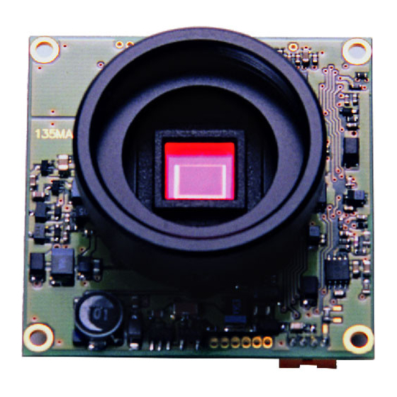
①
①CCD FRONT FACE
・The light receiving face of the CCD camera
(Dirt, water or oil deposits on the CCD will cause an unclear picture on the
monitor. Attach the lens cap to protect the lens and CCD from
contamination and damage.)
②LENS MOUNT
・Mount for the lens (Thread type)
③FOCUSING ADJUSTMENT SCREWS
・There are 3 hex. adjustment screws each placed at intervals of 120゜for
fine focusing of the lens.
④TERMINAL FOR AUTO-IRIS LENS (VIDEO CONTROL)
・The terminal for a Video-driven auto-iris lens. Do not connect a DC-
driven auto-iris lens to this terminal.
⑤TERMINAL FOR AUTO-IRIS LENS (DC CONTROL)
・The terminal for a DC-driven auto-iris lens. Do not connect a Video-
driven auto-iris lens to this terminal.
⑥IRIS LEVEL VOLUME
・By controlling the volume, the iris level of a DC iris lens can be adjusted.
⑦AE MODE CONTROL SWITCH
・The switch for selecting either electronic iris or electronic shutter.
⑧SHUTTER SPEED CONTROL SWITCH
・The switch for the electronic shutter speed control according to the
object.
⑨POWER IN/VIDEO OUT
・The terminal for power input and video signal output. Use the attached
connector with cables for this purpose.
⑩FUNCTION SWITCHES
・ Functional switches for setting video level, mirror image and white balance.
⑪MOUNTING HOLES
・Four φ2.2mm diameter holes in each corner for mounting the camera.
Power Supply and Wiring
If any other power adaptor besides the AD901 is used, please use a
stabilized power adaptor designed for DC+12V ± 10%, with a current
is
capacity of more than 250mA. Use the optional DC plug if the shape or
polarity of the DC plug of the power adaptor to be used is not compatible
with the camera.
The wiring on the connector must be exact.
Connector with cables Hex. Wrench
② ③
④
⑤
⑪
⑩
⑨
.
⑥
⑦
⑧
Advertisement

Related Manuals for Watec W-01CDB3


Summary of Contents for Watec W-01CDB3
- Page 1 Cautions for Safety Description of Parts The W-01CDB3 is designed to be used safely; however, it may lead to ① ② ③ ④ ⑤ physical accident caused by fire and electric shock if not used correctly. Therefore, please keep and read the“Cautions for safety”for protection ...
-
Page 2: Specifications
Specifications As shown in the figure on the right. The W-01CDB3 Model W-01CDB3 (NTSC) W-01CDB3 (PAL) provides four mounting holes, one in each corner of the ...
Need help?
Do you have a question about the W-01CDB3 and is the answer not in the manual?
Questions and answers