Table of Contents
Advertisement
Quick Links
Advertisement
Table of Contents

Subscribe to Our Youtube Channel
Related Manuals for Daitsu FSTD SLIM - EC FLEX Series


Summary of Contents for Daitsu FSTD SLIM - EC FLEX Series
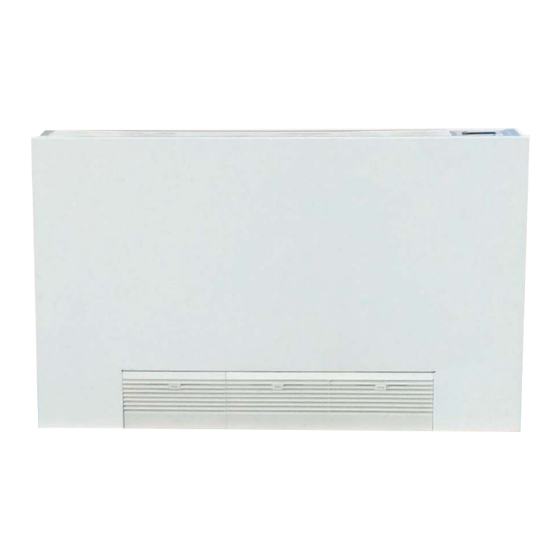
- Page 1 INSTALLATION AND MAINTENANCE MANUAL FLOOR CEILING SLIM FSTD SLIM - EC FLEX Serie FSTD SLIM - EC FLEX Edition Models FSTD SLIM-01 FSTD SLIM-01-4T FSTD SLIM-02 FSTD SLIM-02-4T FSTD SLIM-03 FSTD SLIM-03-4T FSTD SLIM-04 FSTD SLIM-04-4T FSTD SLIM-05 FSTD SLIM-05-4T...
-
Page 2: Sk2019 Fstd-Slim-Ec-Flex-001
Page 1 of 71 INVESTING IN QUALITY, RELIABILITY & PERFORMANCE ISO 9001 QUALITY World Leading Design and Technology Every product is manufactured to meet Equipped with the latest air-conditioning test rooms the stringent requirements of the and manufacturing technology, we produce over internationally recognized ISO 9001 50,000 fan coil units each year, all conforming to the standard for quality assurance in design,... -
Page 3: Table Of Contents
Page 2 of 71 Table of Contents A. Technical Data ..................................5 General Description ................................ 5 General Specification ..............................6 2-Pipe Systems ................................ 6 4-Pipe Systems ................................ 7 Coil Data ..................................8 2-Pipe Systems ................................ 8 4-Pipe Systems ................................ 8 Sound Power Data ................................ - Page 4 Page 3 of 71 Low Temperature Protection of Indoor Coil in Winter ....................40 E. Networking System ................................41 Master-Slave Network ..............................41 Master Unit Control Settings ..........................41 Master-Slave Network Setup ..........................42 Master-Slave Communication Method ........................44 Open Modbus protocol ..............................45 F.
- Page 5 Page 4 of 71 Model Code Nomenclature FSTD SLIM - FLEX- EC EC Motor Configuration Flexible function onboard PCB with zone FLEX control functionality. Chilled/Hot Water, 4-Pipe Unit Sizes. See General Specification 01 - 05 section A for cooling and heating capacities FSTD SLIM Super Slim Universal Unit...
-
Page 6: Technical Data
Page 5 of 71 Technical Data General Description The product represents all-in-one solution for cooling, heating and dehumidification. It achieves high energy saving levels as it can be combined with low-temperature heat generators such as heat pump, condensing boilers and solar collectors. With its sophisticated temperature regulator, it guarantees thermal comfort in every season. -
Page 7: General Specification
Page 6 of 71 General Specification 2-Pipe Systems Product range: FSTD SLIM-EC Super Slim Universal Fan Coil with EC Motor FSTD SLIM~-EC Super Slim Universal Unit 2-pipe with EC Motor FSTD SLIM-[Size]-EC Configuration 2-pipe Number Of Fan Blowers 230/1/50 Power Supply (V/Ph/Hz) Unit Configuration 220/1/60... -
Page 8: 4-Pipe Systems
Page 7 of 71 4-Pipe Systems Product range: FSTD SLIM-4T~-ECM Super Slim Universal Unit 4-pipe with EC Motor FSTD SLIM-4T~-ECM Super Slim Universal Unit 4-pipe with EC Motor FSTD SLIM-[Size]-4T-EC Configuration 4-pipe Number Of Fan Blowers 230/1/50 Power Supply (V/Ph/Hz) Unit Configuration 220/1/60 ~TOTAL: Complete function onboard PCB with integrated group control... -
Page 9: Coil Data
Page 8 of 71 Coil Data 2-Pipe Systems Fin width Fins per No. of No. of Tube Ø Model height Length (mm) Inch Rows Circuits (mm) (mm) (mm) FSTD SLIM-01 FSTD SLIM-02 12.7 9.52 FSTD SLIM-03 FSTD SLIM-04 FSTD SLIM-05 1101 4-Pipe Systems Cooling Coil... -
Page 10: Sound Power Data
Page 9 of 71 Sound Power Data Model FSTD SLIM-01 H(1200 M(1000 L(800 Speed 500RPM 600RPM 700RPM 800RPM 900RPM 1000RPM 1100RPM 1200RPM 1300RPM 1400RPM RPM) RPM) RPM) Sound Power dB(A) 50.2 44.2 38.1 27.4 30.2 33.8 38.1 41.2 44.2 50.2 54.5 20 Hz 13.8... - Page 11 Page 10 of 71 Model FSTD SLIM-02 H(1200 M(1000 L(800 Speed 500RPM 600RPM 700RPM 800RPM 900RPM 1000RPM 1100RPM 1200RPM 1300RPM 1400RPM RPM) RPM) RPM) Sound Power dB(A) 52.2 46.2 40.1 29.4 32.2 35.8 40.1 43.2 46.2 49.0 52.2 54.0 56.5 20.0 Hz 15.8 17.7...
- Page 12 Page 11 of 71 Model FSTD SLIM-03 Speed H (1200RPM) M 1000RPM) L (800RPM) 800RPM 900RPM 1000RPM 1100RPM 1200RPM 1300RPM 1400RPM Sound Power dB(A) 54.7 48.9 42.3 42.3 45.8 48.9 51.8 54.7 56.6 59.0 20.0 Hz 10.0 11.4 10.0 25.0 Hz 31.5 Hz -0.9 -0.9...
- Page 13 Page 12 of 71 Model FSTD SLIM-04 Speed H (1200RPM) M 1000RPM) L (800RPM) 800RPM 900RPM 1000RPM 1100RPM 1200RPM 1300RPM 1400RPM Sound Power dB(A) 55.1 49.8 42.9 42.9 46.6 49.8 52.8 55.1 57.3 59.8 20.0 Hz 17.9 13.0 13.5 13.5 12.0 13.0 18.3...
- Page 14 Page 13 of 71 Model FSTD SLIM-05 Speed 600RPM 700RPM 800RPM 900RPM 1000RPM 1100RPM 1200RPM 1300RPM 1400RPM (1300RPM) (1100RPM) (900RPM) Sound Power dB(A) 56.7 51.8 45.1 35.6 39.1 42.6 45.1 48.9 51.8 54.3 56.7 58.7 20.0 Hz 15.9 15.7 16.3 23.2 17.9 10.8...
-
Page 15: Dimensions
Page 14 of 71 Dimensions MODEL FSTD SLIM-01 FSTD SLIM-02 FSTD SLIM-03 FSTD SLIM-04 FSTD SLIM-05 1140 1340 1540 1116 1316 1516 1033 1233 (All dimensions in mm) SK2019 FSTD-SLIM-EC-FLEX-001_01... -
Page 16: Valve Information (Optional)
Page 15 of 71 Valve Information (Optional) 2-Way 3/4” Valve Body Valve Body Dimensions (mm) Valve Code (valve body + ON/ OFF thermoelectric actuator) SGS14HFCA-23010101 (G3/4”) 3-Way 3/4” Valve Body Valve Body Dimensions (mm) Valve Code (valve body + ON/ OFF thermoelectric actuator) SGS14HFCA-23010102 (G3/4”) - Page 17 Page 16 of 71 2-Way 1/2" Valve Body Valve Body Dimensions (mm) Valve Code (valve body + ON/ OFF thermoelectric actuator) SGS14HFCA-23020101 19.5 (G1/2”) Differential Pressure Chart SK2019 FSTD-SLIM-EC-FLEX-001_01...
- Page 18 Page 17 of 71 Actuator Model DR-16-230B DR-16-24B DR-15B-24B Normal closed Normal closed Normal closed Voltage 230Vac 24Vac 24Vac Working force 90~125N 90~125N 90~125N Time 4.5min 4.5min 4.5min Power Full stroke 3.5mm 3.5mm 5.0mm Imax 150mA 250mA 250mA Wires 2-wire 2-wire 3-wire (red, blue, black) SK2019 FSTD-SLIM-EC-FLEX-001_01...
-
Page 19: Installation
Installation Safety Precautions • When installing, performing maintenance or servicing Daitsu fan coil units observe the precautions stated in this manual as well as those stated on the labels attached to the unit. • Ensure all local and national safety codes, laws, regulations, as well as general electrical and mechanical safety guidelines are followed for installation, maintenance and service. -
Page 20: Installation And Location
Page 19 of 71 Installation and Location The unit location should be established by the installation designer, services engineer or by a technically competent person before installation. It should take into account the technical requirements as well as the relevant current laws and regulations. -
Page 21: Front Panel Removal
Page 20 of 71 Front Panel Removal Step 1: Unlock grill and remove the filter. Step 2: Lift the front panel and remove it. Electrical Connection The fan coil comes fully wired and only requires connecting to the mains electricity supply and to any room controls. Remove the front panel, then control box is shown below. - Page 22 Page 21 of 71 TOTAL-version unit FLEXI-version unit Thermostat-(optional) SK2019 FSTD-SLIM-EC-FLEX-001_01...
-
Page 23: Piping Connections
Page 22 of 71 Piping Connections The fan coils have been designed and made for installation in heating and air-conditioning systems. The characteristics of the water fittings are given below: Main pipes connection The position of the water fittings may be reversed from left to right in the factory. Installation diagram of water connections 1. -
Page 24: Valve And External Drain Pan Installation
Page 23 of 71 Valve and External Drain Pan Installation Horizontal type Piping for 2-Pipe System Water Outlet 3/4” Water Inlet 3/4” 3-Way 4 Port Valve 3/4” Horizontal Drain Pan Piping for 4-Pipe System 2-Way Valve 1/2” for Heating Coil 2-Way Valve 1/2”... - Page 25 Page 24 of 71 Vertical type Piping for 2-Pipe System 3-Way 4 Port Valve 3/4” Water Outlet 3/4” Water Inlet 3/4” Vertical Drain Pan Piping for 4-Pipe System Chilled Water Outlet 1/2” 2-Way valve 1/2” for Cooling Coil Hot Water Outlet 1/2” 2-Way Valve 1/2”...
-
Page 26: Maintenance
Page 25 of 71 Maintenance General Maintenance 1. Installation and maintenance should be performed by qualified personnel who are familiar with local codes and regulations, and are experienced with this type of appliance. 2. Confirm the unit has been switched OFF before installing or service. 3. -
Page 27: Fan Motor Assembly Maintenance
Page 26 of 71 Fan Motor Assembly Maintenance Step 1: Remove the front panel. Step 2: Loosen screws on the mounting brackets. EC motor can be removed. Step 3: Once finished with maintenance, remount the front panel. Water Fittings Interchange The unit is not easy to change water fitting position. -
Page 28: Control Specifications: Complete Function Pcb - Total Type Control
Page 27 of 71 Control Specifications: Complete Function PCB – TOTAL Type Control Abbreviations Ts = Setting temperature AUX1 = Hot water free contact Tr = Room air temperature AUX2 = Chilled water free contact Ti1 = Chilled water coil temperature MTV1 = Chilled water valve Ti2 = Hot water coil temperature MTV2 = Hot water valve... -
Page 29: Wiring Diagrams
Page 28 of 71 Wiring Diagrams Standard EC-TOTAL Type Control PCB IPA19-DL-EC-S1 EC-S1 Unit wiring scheme DIPA-S1 SW1-5: set the unit address SW6: set unit type :master or slave NEXT UNIT Mode Configuration SW7=0;SW8=0; unit operates in cooling/heating SW7=0;SW8=1; unit operates in cooling/heating w/booster FUSE SW7=1;SW8=0 ;... -
Page 30: Master-Slave Networking Wiring Diagram
Page 29 of 71 Master-Slave Networking Wiring Diagram FLOAT EH2 EH1 PR2 PR1 FLOAT EH2 EH1 PR2 PR1 FLOAT EH2 EH1 PR2 PR1 LED display / IR receiver LED display / IR receiver LED display / IR receiver X-DISI A B A B X-DISI A B A B X-DISI... -
Page 31: Configuration Settings
Page 30 of 71 Configuration Settings DIPA-S1 DIPB-S2 SW1-SW5 Network address SW5/SW6 Fan Qty setting setting SW5=0 Single fan application SW6=1 SW5= Twin fans application Master / Slave setting SW6=1 SW6=1 Master SW6=0 Slave Preheat temperature setting SW4=1 SW4=0 SW7/SW8 Operating mode SW7=0 Cooling and heating modes available SW8=0 230VAC on/off valve setting... - Page 32 Page 31 of 71 Fan Coil Unit ON/OFF There are 3 ways to turn the system on or off: a) By the ON/OFF button on the remote handset or wired wall pad; b) By the programmable timer on the handset or wired wall pad. c) By the manual control button on fan coil unit.
-
Page 33: Control Logics For 2-Pipe System
Page 32 of 71 Control Logics for 2-Pipe System With Valve Configuration COOL MODE a) MTV2, AUX1 and electric heater are always off. b) If Tr ≥ Ts + 1ºC (or + 4ºC if economy contact is activated), then cool operation is activated and MTV1 and AUX2 are turned on. - Page 34 Page 33 of 71 Heat mode with electrical heater as primary heat source a) MTV1, MTV2, and AUX2 are always off b) If Ti2 ≤ 30ºC (or Ti2 is damaged or disconnected), AND if Tr ≤ Ts-1ºC (or -4ºC if economy contact is activated), heat operation is activated, electrical heater and AUX1 are turned on.
- Page 35 Page 34 of 71 AUTOMODE Auto cool/heat/heat with electric heater as booster Every time the unit is turned on, MTV1 is on, AUX1, AUX2 and fan are off. MTV2 and heater are always off. After 120secs, the subsequent operation mode is decided according to the following programs: a) If the coil temperature sensor (Ti1) ≥...
-
Page 36: Without Valve Configuration
Page 35 of 71 Without Valve Configuration COOL MODE a) Electric heater, AUX1, MTV1 and MTV2 are always off. b) If Tr ≥ Ts + 1ºC (or + 4ºC if economy contact is activated), then cool operation is activated and AUX2 is turned on. Indoor fan runs at set speed. - Page 37 Page 36 of 71 Over heat protection of indoor coil in post-heat a) If Ti1 ≥ 75ºC, then AUX1 is turned off, indoor fan remains on and runs at high speed. b) If Ti1 < 70ºC, then AUX1 is turned on, indoor fan remains on and runs at set speed. If the indoor coil temperature sensor is damaged, then the protection mode will be overridden and the unit will work according to the pre-heat and post-heat program.
-
Page 38: Control Logics For 4-Pipe System
Page 37 of 71 Control Logics For 4-Pipe System Note: 4-pipe system must always be equipped with 2 valves. COOL MODE a) MTV2, AUX1 and Electrical Heater are always off. b) If Tr ≥ Ts + 1ºC (or + 4ºC if economy contact is activated), then cool operation is activated, MTV1 and AUX2 are turned on. Indoor fan runs at set speed. - Page 39 Page 38 of 71 PRE-HEAT Without Electrical Heater a) If Ti2 < 36ºC [or 28ºC depends on DIP setting], then MTV2 and AUX1 are on, then indoor fan remains off. b) If Ti2 ≥ 38ºC [or 30ºC depends on DIP setting], then MTV2 and AUX1 are on, then indoor fan runs at set speed. If indoor coil temperature sensor is damaged, then pre-heat time is set for 2 minutes and indoor fan runs at set speed.
-
Page 40: Sleep Mode
Page 39 of 71 Sleep Mode a) The sleep mode can only be set when the unit is in cool mode or heat mode. b) If the sleep mode is activated when the unit is in cool mode, then the indoor fan will run at low speed and Ts will increase by 2ºC over 2 hours. -
Page 41: On/Off Switch On The Front Panel
Page 40 of 71 On/Off Switch On The Front Panel a) This is a TACT switch to select Cool→Heat→Off operation mode. b) In COOL mode, the set temperature of the system is 24ºC with auto fan speed. There are no timer and sleep modes. In HEAT mode, the set temperature of the system is 24ºC with auto fan speed. -
Page 42: Networking System
Page 41 of 71 Networking System Master-Slave Network The control PCB can be set either as a master unit or slave unit. Mater Unit Function a) The master unit sends data regarding its setting to the slave unit. b) The master unit settings are unit ON/OFF, Mode, Fan Speed, Timer, Clock, Set Temperature, Louver Function, and Sleep Function for handset operation. -
Page 43: Master-Slave Network Setup
Page 42 of 71 Master-Slave Network Setup 1) Disconnect the communication plug from the control box 2) Communication plug A, B, A, B is printed on the main PCB. When you connect the wires, please ensure connection of A to A and B to B. 3) Connection wire i. - Page 44 Page 43 of 71 First unit Middle unit Last unit iii. Wire connection check a) After the wire connection is completed, please check that the wire colours correspond. b) Check the wire contact by using a multimeter. contact contact contact contact contact contact...
-
Page 45: Master-Slave Communication Method
Page 44 of 71 Master-Slave Communication Method There are two modes for the master-slave structure. Global Control communication The master unit will broadcast the settings to all slave units. During normal operation, slave units can receive commands from its wireless handset and wall pad control panel. Upon receiving the master global commands, all slave unit settings will be replaced by the master settings. -
Page 46: Open Modbus Protocol
Page 45 of 71 Open Modbus protocol Transfer Mode: RTU, BAUD Rate: 9600bps, 8 data bit, 1 stop bit, None parity bit The communications require a delay of 80ms between reading an answer and sending the next command. All temperatures are equal to reading data*10 accuracy: 0.1 degree C. - Page 47 Page 46 of 71 Holding Register table: Description Address Type* Remark Cooling mode = 01(H) Humidify mode = 02(H) Mode setting 300000 Fan mode = 04(H) Heating mode = 08(H) Auto mode = 10(H) Low speed = 04(H) Medium speed = 02(H) Fan speed setting 300001 High speed = 01(H)
- Page 48 Page 47 of 71 Input Register table: Description Address Type* Remark Dip switch 1 status 400000 Dip switch 2 status 400001 Room temperature sensor 400002 Ti1 temperature sensor 400003 Ti2 temperature sensor 400004 Bit0 = Room temperature sensor error Bit1 = Ti1 temperature sensor error Bit2 = Ti2 temperature sensor error Bit3 = Float switch error Bit4 = Indoor coil low temperature protection...
-
Page 49: Control Specifications: Flexible Function Pcb - Flexi Type Control
Page 48 of 71 Control Specifications: Flexible Function PCB – FLEXI Type Control Features a) Integrated fan relays for zone control applications. b) ON/OFF thermostat input and low-voltage modulating fan speed input flexibility. Simple error diagnostic and LED error display. I/O Port Definitions Code 2-Pipe... -
Page 50: Wiring Diagrams
Page 49 of 71 Wiring Diagrams Standard EC-FLEXI Type Control PCB EC-W1B unit wiring scheme IPA19-DL-EC-W1B 0~10Vdc from thermostat ALARM FUSE1 Main power supply L M H EH COM PROG1 230Vac 1Ph EMI1 RLY2 2 pipe sensor (Ti1) EH 2.5mm2 Cooling valve signal (230Vac) EMI2 MOTOR1... -
Page 51: Control Logics Specification
Page 50 of 71 Control Logics Specification Unit Power On/Off a) The unit is turned ON when any of the fan speed inputs (H/M/L) are ON, or modulating signal input is more than2.0 VDC. b) The unit is turned OFF only if all of the fan speed inputs (H/M/L) are OFF and modulating signal input is less than 2.0 VDC. Alarm Protection and Error Display a) If the float switch is open for 5 minutes or EC motor is failed, then the (NC) voltage-free alarm contact shall be open and the (NO) voltage free alarm contact shall be closed. -
Page 52: User Interface
Page 51 of 71 User Interface Remote Handset for TOTAL Type Control Interchange F and C on Display Press up and down buttons for 3 seconds, then release. Louver It is not available. Swing It is not available. Attention When unit with handset is the master unit, its settings are automatically sent to the slave units;... -
Page 53: Wired Wall Pad Controller
Page 52 of 71 Wired Wall Pad Controller Real Time display Day display Timer display Mode display Temperature display Fan speed display Button display Network icon Sleep icon Master-Slave Key lock SK2019 FSTD-SLIM-EC-FLEX-001_01... - Page 54 Page 53 of 71 1. Buttons function Button Name ONOFF MODE DOWN Function Switch on or off Switch between Change Fan Switch Modify Modify the unit modes Speed interfaces parameters parameters Press to change function setting: (CNT stands for pressing times) (1)...
- Page 55 Page 54 of 71 When DIP SW2=OFF, room temperature is shown on temperature display area. 6. Mode setting Press to set COOL, HEAT, FAN or DRY mode alternatively. 7. Key Lock Press to set key lock function. Key lock icon is on or off when key lock function is set to on or off. 8.
- Page 56 Page 55 of 71 13. Parameter checking Press six times to enter parameter checking interface. Local unit parameter is shown in temperature display area. Unit number is shown in real time hour area and parameter number is shown in real time minute area. For example, 2:03 stands for No.2 unit and No.3 parameter.
-
Page 57: Thermostat For Ec-Flexi Type Control
Page 56 of 71 Thermostat for EC-FLEXI Type Control LED display Legend: S1: real clock time S2: Data display S3: Relative humidity S4: Room temperature S5: Setting temperature S6: Room PM2.5 (ug/m3) S7: Room CO2 (ppm) S8: Room VOCs (PPb) S9: Degree C S10: Degree F S11: Timer ON/OFF... -
Page 58: Parameters Setting
Page 57 of 71 6. Keypad lock: Press for 5 seconds to display will be shown. Keypad lock function is working. Under this function, any keypad is locked. Press for 5 seconds to display will disappear, keypad lock function is not working. 7. -
Page 59: Ac/Ec Fan Coil Thermostat
Page 58 of 71 No9 stands for CO2 band setting: 100~500, default: 200 No10 stands for VOCs setting: 460~1200, default: 800 No11 stands for VOCs band setting: 100~500, default: 200 No12 stands for VOCs setting: 30~70, default: 50 No13 stands for VOCs band setting: 10~30, default: 10 No14 stands for unit address setting: 0~31, default: 0 No15 stands for ESP setting: 0~100%, default: 40% No16 stands for temperature sensor setting:... -
Page 60: I/O Table
Page 59 of 71 No16 stands for temperature sensor setting: 0=inner and external sensor are used. Inner sensor is to show room temperature. External sensor is used to show water inlet temperature. 1=External sensor is connected, room temperature is based on external sensor. External sensor is not connected, room temperature is based on inner sensor No17 stands for unit configuration setting: 0=2-pipe... -
Page 61: Thermostat Control Specification
Page 60 of 71 AC/EC-S4 Thermostat Wiring scheme Legend: L1: Hi,M,L, V1, V2 power supply; High speed contact; Med: Medium speed contact; Low speed contact; Cooling valve contact; Heating valve contact; S1 C1 A1 A2 Remote on/off contact; Cooling status signal contact; Heating status signal contact;... - Page 62 Page 61 of 71 Low Temperature Protection of Indoor Coil (Parameter 16=0) If Ti1 ≤ 2 ºC for 2 minutes, then MTV1 and AUX1 are turned off. If indoor fan is set for low speed, then it will run at medium speed.
-
Page 63: 4-Pipe Thermostat Control Specification (Parameter 17=1)
Page 62 of 71 7) Modulating valve control signal (Parameter 19=1) DA1 is based on Tr, Ts PI calculation to output 0~10 VDC. Minimum DA1 output is according to Modbus address 310000 setting. 8) PRO1(C1) input The unit is on. If C1 input is closed for 60s, the unit is turned OFF. If C1 input is opened for 10s, the unit will be turned ON again. - Page 64 Page 63 of 71 5) Auto Fan Speed COOL MODE HEAT MODE Fan speed cannot change until it has run at this Fan speed cannot change until it has run at this speed for more than 30 seconds. speed for more than 30 seconds. After 30 seconds the fan speed is modulated according to the difference between the room temperature and the set temperature.
-
Page 65: 2-Pipe +Floor Heating Control Specification (Parameter 17=2)
Page 64 of 71 2-pipe +floor heating control specification (Parameter 17=2) 1) Cooling mode If Tr ≥ Ts + 1ºC (Parameter5 setting), then cool operation is activated. MTV1 and AUX1 are turned on. Indoor fan runs at set speed. If Tr < Ts, then cool operation is terminated and MTV1 and AUX2 are turned off. Indoor fan runs at set speed or stop according to parameter18 setting. -
Page 66: Modbus Communication Protocols For Thermostat
Page 65 of 71 MODBUS Communication Protocols for Thermostat Serial number Specification Protocol Specification Media RS485 Baud Rate 9600 BPS Transmit Mode Data Unit Additional address + Function code + Data + CRC Address 1-32 1, 2, 3, 4, 6 Function Code 0-255 DATA... - Page 67 Page 66 of 71 03 Read Holding Registers: Protocol Function Code Holding Register Addresses Data Define Specification “0”=OFF, ”01”=ON, 03/06 State 02=low temperature protection (R) 03/06 Mode 1=Cool, 2=Heat, 3=Ventilation Set Room 03/06 Temperature (16 - 30℃) Temperature 03/06 Fan Mode 00=High, 01=Med, 02=Low, 03=Auto Model 01=DA, 02=DB, 11=FCV2...
-
Page 68: Sensor Resistance R-T Conversion Table
Page 67 of 71 Sensor Resistance R-T Conversion Table Resistance : R (25°C) = 10KΩ ± 1% Beta Constant : B (25/85) = 3977 ± 1% Rmin Rnom Rmax Rmin Rnom Rmax ( °C ) (KΩ) (KΩ) (KΩ) ( °C ) (KΩ) (KΩ) (KΩ) - Page 69 Page 68 of 71 Resistance : R (25°C) = 10KΩ ± 1% Beta Constant : B (25/85) = 3977 ± 1% Rmin Rnom Rmax Rmin Rnom Rmax ( °C ) (KΩ) (KΩ) (KΩ) ( °C ) (KΩ) (KΩ) (KΩ) 5.614 5.759 5.907 1.417...
-
Page 70: Troubleshooting
Page 69 of 71 Troubleshooting Symptoms Cause Remedy The fan coil does not - Check for presence of voltage No voltage start up - Check fuse on board Mains switch in the “OFF” position - Place in the “ON” position Faulty room control - Check the room control - Check fan motor... -
Page 71: Accessories Descriptions
Page 70 of 71 Accessories Descriptions Electrical Heater Electric Heater module is supplied for winter heating as an alternative to the auxiliary hot water coil. Electric Heater is installed in the same way and same position as the Auxiliary 1 row heating coil for 4-pipe system. Note: Airflow should not drop below the values for minimum speed. -
Page 72: Auxiliary External Drain Pan
Page 71 of 71 Auxiliary External Drain Pan DPANPS-UNSL-RH is a painted steel drain pan for suspended ceiling installation or built-in horizontal installation with right- sided coil connections. DPANPS-UNSL-LH is a painted steel drain pan for suspended ceiling installation or built-in horizontal installation with left-sided coil connections. - Page 73 Eurofred S.A. Marqués de Sentmenat 97 08029 Barcelona www.eurofred.es...
Need help?
Do you have a question about the FSTD SLIM - EC FLEX Series and is the answer not in the manual?
Questions and answers