Table of Contents
Advertisement
Quick Links
Advertisement
Table of Contents
Troubleshooting

Related Manuals for Daitsu L/M-STAT AMV Series


Summary of Contents for Daitsu L/M-STAT AMV Series
- Page 1 FDLA – V / P – AC MOTOR SK2018 GLOBAL FDLA-V/P-AC-001...
- Page 2 Page 1 of 51 INVESTING IN QUALITY, RELIABILITY & PERFORMANCE ISO 9001 QUALITY World Leading Design and Technology Every product is manufactured to meet Equipped with the latest air-conditioning test rooms the stringent requirements of the and manufacturing technology, we produce over internationally recognized ISO 9001 50,000 fan coil units each year, all conforming to the standard for quality assurance in design,...
-
Page 3: Table Of Contents
Page 2 of 51 Table of Contents A. Technical Data ................................... 5 A.1. General Description ................................5 A.2. General Specifications ................................ 6 A.2.1. 2-pipe Systems ................................6 A.2.2. 4-pipe Systems ................................8 A.3. Coil Data ..................................... 9 A.4. Dimensional Drawings ..............................10 A.5. - Page 4 Page 3 of 51 D.10. On/Off Switch on LED Display Panel..........................34 D.11. Electric Heater Safety Switch ............................34 D.12. Low Temperature Protection of Indoor Coil in Winter ....................34 D.13. LED Display and Error Description ..........................35 D.14. LED Display on Master/Slave Connection........................36 D.15.
- Page 5 Page 4 of 51 Model Code Nomenclature FDLA - (3R) - 09 - V S + Left Side Coil Right Side Coil Complete function onboard PCB with integrated group control functionality. Terminal strip only Chilled/Hot Water, 4-Pipe Chilled/Hot Water, 2-Pipe Unit Sizes.
-
Page 6: General Description
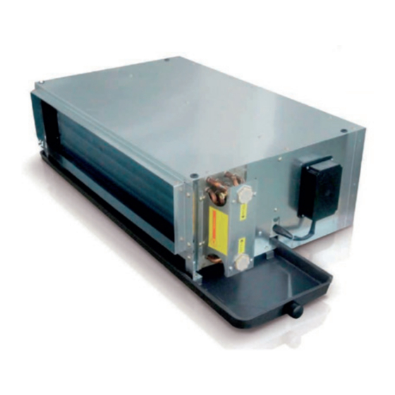
Page 5 of 51 General Description The Duct Fan Coil is designed to meet and exceed the demanding requirements for efficiency and quiet operation. Structure The structure is made from heavy gauge galvanized steel panels with couplings for the connection of ducting and a gravity drain pan with insulation for condensation. -
Page 7: General Specifications
Page 6 of 51 General Specifications A.2.1. 2-pipe Systems Product range: FDLA(3R) Low Static Hydronic Ducted Fan Coil Unit FDLA(3R)-V~ Hydronic Ducted 2-pipe Unit with 3-row Coils and AC motor FDLA(3R)-[Size]-V~ Configuration 2-pipe Number Of Fan Blowers Single Twin Three Four Three Four... - Page 8 Page 7 of 51 Product range: FDLA(4R) Low Static District Cooling Hydronic Ducted Fan Coil Unit FDLA(4R)-V~ Hydronic Ducted 2-pipe Unit with 4-row Coils and AC motor FDLA(4R)-[Size]-V~ Configuration 2-pipe Number Of Fan Blowers Single Twin Three Four Three Four Unit Configuration 230 / 1 / 50 Power Supply (V/Ph/Hz)
-
Page 9: A.2.2. 4-Pipe Systems
Page 8 of 51 A.2.2. 4-pipe Systems Product range: FDLA(3+1R) Low Static Hydronic Ducted Fan Coil Unit FDLA(3+1R)-P~ Hydronic Ducted 4-pipe Unit with 3-row Coils and AC motor FDLA(3+1R)-[Size]-P~ Configuration 4-pipe Number Of Fan Blowers Single Twin Three Four Three Four Unit Configuration 230 / 1 / 50... -
Page 10: Coil Data
Page 9 of 51 Coil Data 3-row Coils Fin height Fin Length Fins per No. of Fin width No. of Tube Ø Model (mm) (mm) Inch Rows (mm) Circuits (mm) FDLA(3R)-09 FDLA(3R)-12 FDLA(3R)-15 FDLA(3R)-18 FDLA(3R)-24 12.7 9.52 FDLA(3R)-30 1280 FDLA(3R)-34 1380 FDLA(3R)-40 1480... -
Page 11: Dimensional Drawings
Page 10 of 51 Dimensional Drawings Model FDLA-09 φ14 FDLA-12 φ14 FDLA-15 φ14 FDLA-18 1155 φ14 FDLA-24 1255 φ14 FDLA-30 1335 1285 1285 1310 1655 φ14 FDLA-34 1435 1385 1385 1410 1755 φ14 FDLA-40 1575 1525 1525 1550 1855 φ14 FDLA-54 1435 1385... -
Page 12: Sound Data
Page 11 of 51 Sound Data Sound Power (Inlet + Radiated) Model FDLA-09 FDLA-12 FDLA-15 FDLA-18 FDLA-24 speed Sound Power 59.5 58.2 60.8 60.5 56.7 55.3 62.6 61.6 56.8 65.4 63.7 60.5 dB(A) 17.3 17.9 14.6 17.7 20.4 23.8 21.8 23.2 18.8 20.6... - Page 13 Page 12 of 51 Model FDLA-30 FDLA-34 FDLA-40-V FDLA-54 FDLA-60-V speed Sound Power 63.9 62.5 58.1 66.3 65.4 61.5 68.6 66.5 63.4 69.1 65.9 61.1 70.1 68.4 66.7 dB(A) 24.3 18.3 22.2 21.5 21.8 25.6 20.7 26.5 17.3 19.7 21.8 18.4 18.2 19.8...
-
Page 14: Valve Information (Optional)
Page 13 of 51 Valve Information (Optional) A.6.1. On/Off Ball Valve Model SGS14HFCA-23030101 3-way ball valve with 3/4” connectors and on/off motorized actuator SGS14HFCA-23030102 2-way ball valve with 3/4” connectors and on/off motorized actuator Specifications Materials Medium: Cool/Hot water or 60% glycol Body: Forged brass, nickel plated Structure: Two way or Three way Ball: Chrome plated brass... -
Page 15: A.6.2. Modulating Valve Model
Page 14 of 51 A.6.2. Modulating Valve Model SGS14HFCA-23050201 3/4" inch 2-way modulating valve and 24VAC actuator with 0-10VDC input Features • 24V AC power supply • 0~10VDC control signal • Bi-directional modulating proportional control. Technical data • Working media: cool/hot water or with 60% glycol •... -
Page 16: Safety Precautions
Page 15 of 51 Safety Precautions • When installing, performing maintenance or servicing Polar Air fan coil units observe the precautions stated in this manual as well as those stated on the labels attached to the unit. • Ensure all local and national safety codes, laws, regulations, as well as general electrical and mechanical safety guidelines are followed for installation, maintenance and service. -
Page 17: Location
Page 16 of 51 Location Before installing and running the unit, please check the following: There must be enough space for unit installation and maintenance. Please refer to below figure for the unit's outlines and dimensions and for the minimum distance between the unit and the obstacle/ any obstructions/ its surroundings. Please ensure there is enough space for piping connections and electrical wiring. - Page 18 Page 17 of 51 CAUTION Make sure the top of the unit is level after installation. The drain pan is designed with a slight gradient to facilitate drainage. CAUTIONS Dimension M and N are determined by air duct design. Air duct should be fire-proof. Please refer to concerned country national and local regulation. Circulatory air pressure drop should be approximately equal to the External Static Pressure.
-
Page 19: Insulation
Page 18 of 51 Insulation 1. The insulation design and materials should be complying with local and national codes and regulations. 2. Chilled water pipes and all parts on the pipes should be insulated. 3. It is also necessary to insulate the air duct. Air Duct Connection 1. -
Page 20: Electrical Connection
Page 19 of 51 Electrical Connection Wiring connection must be done according to the wiring diagram on the unit. The unit must be GROUNDED well. An appropriate strain relief device must be used to attach the power wires to the terminal box. A 20mm hole is designed on the terminal box for field installation of the strain relief device. - Page 21 Page 20 of 51 T1 Version Unit Controlled by Thermostat: T version unit with on/off valve AC/EC-S4 Thermostat Wiring scheme 24Vac Orange (L) Brown (M) Legend: L1: Hi,M,L, V1, V2 power supply; High speed contact; Yellow (H) Med: Medium speed contact; Low speed contact;...
-
Page 22: General Maintenance
Page 21 of 51 General Maintenance Installation and maintenance should be performed by qualified personnel who are familiar with local codes and regulations, and are also experienced with this type of appliance. Confirm that the unit has been switched OFF before installing or servicing the unit. A good general maintenance plan will prevent damage to and unexpected shutting down of the equipment. -
Page 23: Coil Direction Interchange
Page 22 of 51 Coil Direction Interchange Remove 4 screws for to remove the drain pan. Remove 6 screws on the both side to remove drain guide. Remove 4 screws on the both side of coil mounting brackets. The complete coil assembly can be taken out easily. Be care for if the coil direction is exchanged on site, water inlet and water outlet need to be exchanged too. -
Page 24: I/O Port Definitions
Page 23 of 51 Abbreviations Ts = Setting temperature AUX1 = Hot water free contact Tr = Room air temperature AUX2 = Chilled water free contact Ti1 = Chilled water coil temperature MTV1 = Chilled water valve Ti2 = Hot water coil temperature MTV2 = Hot water valve I/O Port Definitions Code... -
Page 25: Wiring Diagrams
Page 24 of 51 Wiring Diagrams D.2.1. Standard AC-S1 Control PCB Legend: AC-S1-2018 AC-S1 Unit Wiring with 1Ph EH scheme DIPA-S1 SW1-5: set the unit address SW6: set unit type: master or slave Mode Configuration: SW7=0;SW8=0;unit operates in cooling/heating. SW7=0;SW8=1;unit operates in cooling/heating with booster EH. -
Page 26: D.2.2. Master Slave Networking Wiring Diagram
Page 25 of 51 D.2.2. Master Slave Networking Wiring Diagram FLOAT EH2 EH1 PR2 PR1 FLOAT EH2 EH1 PR2 PR1 FLOAT EH2 EH1 PR2 PR1 LED display / IR receiver X-DISI LED display / IR receiver X-DISI LED display / IR receiver X-DISI A B A B A B A B... -
Page 27: Configuration Settings
Page 26 of 51 Configuration Settings SK2018 GLOBAL FDLA-V/P-AC-001... -
Page 28: D.3.1. Fan Coil Unit On/Off
Page 27 of 51 D.3.1. Fan Coil Unit ON/OFF There are 3 ways to turn the system on or off: a) By the ON/OFF button on the remote handset or wired wall pad; b) By the programmable timer on the handset or wired wall pad. c) By the manual control button on fan coil unit. -
Page 29: Control Logics For 2-Pipe System
Page 28 of 51 Control Logics for 2-Pipe System D.4.1. With Valve Configuration COOL MODE a) MTV2, AUX1 and electric heater are always off. b) If Tr ≥ Ts + 1ºC (or + 4ºC if economy contact is activated), then cool operation is activated and MTV1 and AUX2 are turned on. - Page 30 Page 29 of 51 PRE-HEAT Pre-heat without electrical heater a) If Ti1 < 36ºC [or < 28ºC is selected by DIPB-S2 position SW4], then MTV1 and AUX1 are turned on, indoor fan remains off. b) If Ti1 ≥ 38ºC [or ≥ 30ºC is selected by DIPB-S2 position SW4], then MTV1 and AUX1 are turned on, indoor fan runs at set speed.
-
Page 31: D.4.2. Without Valve Configuration
Page 30 of 51 D.4.2. Without Valve Configuration COOL MODE a) Electric heater, AUX1, MTV1 and MTV2 are always off. b) If Tr ≥ Ts + 1ºC (or + 4ºC if economy contact is activated), then cool operation is activated and AUX2 is turned on. Indoor fan runs at set speed. -
Page 32: Control Logics For 4-Pipe System
Page 31 of 51 Control Logics for 4-Pipe System Note: 4-pipe system must always be equipped with 2 valves. COOL MODE a) MTV2, AUX1 and Electrical Heater are always off. b) If Tr ≥ Ts + 1ºC (or + 4ºC if economy contact is activated), then cool operation is activated, MTV1 and AUX2 are turned on. - Page 33 Page 32 of 51 PRE-HEAT Without Electrical Heater a) If Ti2 < 36ºC [or 28ºC depends on DIP setting], then MTV2 and AUX1 are on, then indoor fan remains off. b) If Ti2 ≥ 38ºC [or 30ºC depends on DIP setting], then MTV2 and AUX1 are on, then indoor fan runs at set speed. If indoor coil temperature sensor is damaged, then pre-heat time is set for 2 minutes and indoor fan runs at set speed.
-
Page 34: Sleep Mode
Page 33 of 51 Sleep Mode a) The sleep mode can only be set when the unit is in cool mode or heat mode. b) If the sleep mode is activated when the unit is in cool mode, then the indoor fan will run at low speed and Ts will increase by 2ºC over 2 hours. -
Page 35: Buzzer
Page 34 of 51 Buzzer If a command is received by the fan coil unit, the master unit will respond with 2 beeps for each setting, while the slave unit will respond with 1 beep. Auto Restart The system uses non-volatile memory to save the present operation parameters when system is turned off or in case of system failure or cessation of power supply. -
Page 36: Led Display And Error Description
Page 35 of 51 LED Display and Error Description LED receiver in ABS housing with 0.5m (SGS14HFCA-01010101) or 1.8m (SGS14HFCA-01010102) pre-wiring Complete Function PCB – S Type Control Fan speed setting LED Display Condition High speed Red LED On Normal Medium speed Yellow LED On Normal... -
Page 37: Led Display On Master/Slave Connection
Page 36 of 51 LED Display on Master/Slave Connection The error message indicating the defect status of all slave units will be shown in LED lights on the master unit. Master unit LED Unit No. Blink Remedy Unit 2 failure RED LED blinks 2 times, stops for 3s Check unit 2 communication plug and fix it Unit 3 failure... -
Page 38: Master-Slave Network
Page 37 of 51 Master-Slave Network The control PCB can be set either as a master unit or slave unit. Mater Unit Function a) The master unit sends data regarding its setting to the slave unit. b) The master unit settings are unit ON/OFF, Mode, Fan Speed, Timer, Clock, Set Temperature, Louver Function, and Sleep Function for handset operation. -
Page 39: D.15.2. Master Slave Network Setup
Page 38 of 51 D.15.2. Master Slave Network Setup 1) Disconnect the communication plug from the control box 2) Communication plug A, B, A, B is printed on the main PCB. When you connect the wires, please ensure connection of A to A and B to B. 3) Connection wire i. - Page 40 Page 39 of 51 First unit Middle unit Last unit iii. Wire connection check a) After the wire connection is completed, please check that the wire colours correspond. b) Check the wire contact by using a multimeter. contact contact contact contact contact contact...
-
Page 41: D.15.3. Master Slave Communication Method
Page 40 of 51 D.15.3. Master Slave Communication Method There are two modes for the master-slave structure. Global Control communication The master unit will broadcast the settings to all slave units. During normal operation, slave units can receive commands from its wireless handset and wall pad control panel. Upon receiving the master global commands, all slave unit settings will be replaced by the master settings. -
Page 42: Open Modbus Protocol
Page 41 of 51 Open Modbus Protocol Transfer Mode: RTU, BAUD Rate: 9600bps, 8 data bit, 1 stop bit, None parity bit The communications require a delay of 80ms between reading an answer and sending the next command. All temperatures are equal to reading data*10 accuracy: 0.1 degree C. - Page 43 Page 42 of 51 Holding Register table: Description Address Type* Remark Cooling mode = 01(H) Humidify mode = 02(H) Mode setting 300000 Fan mode = 04(H) Heating mode = 08(H) Auto mode = 10(H) Low speed = 04(H) Medium speed = 02(H) Fan speed setting 300001 High speed = 01(H)
- Page 44 Page 43 of 51 Input Register table: Description Address Type* Remark Dip switch 1 status 400000 Dip switch 2 status 400001 Room temperature sensor 400002 Ti1 temperature sensor 400003 Ti2 temperature sensor 400004 Bit0 = Room temperature sensor error Bit1 = Ti1 temperature sensor error Bit2 = Ti2 temperature sensor error Bit3 = Float switch error Bit4 = Indoor coil low temperature protection...
-
Page 45: Remote Handset
Page 44 of 51 Remote Handset Interchange F and C on Display Press up and down buttons for 3 seconds, then release. Louver It is not available Swing It is not available Attention When unit with handset is the master unit, its settings are automatically sent to the slave units;... -
Page 46: Wired Wall Pad Controller
Page 45 of 51 Wired Wall Pad Controller Real Time Day display display Timer display Mode display Temperature display Fan speed display Button Sleep Master-Slave Wifi Key lock display icon icon SK2018 GLOBAL FDLA-V/P-AC-001... - Page 47 Page 46 of 51 1. Buttons function Button Name ONOFF MODE DOWN Function Switch on or off Switch between Change Fan Switch Modify Modify the unit modes Speed interfaces parameters parameters Press to change function setting: (CNT stands for pressing times) (1)...
- Page 48 Page 47 of 51 6. Mode setting Press to set COOL, HEAT, FAN or DRY mode alternatively. 7. Key Lock Press to set key lock function. Key lock icon is on or off when key lock function is set to on or off. 8.
- Page 49 Page 48 of 51 13. Parameter checking Press six times to enter parameter checking interface. Local unit parameter is shown in temperature display area. Unit number is shown in real time hour area and parameter number is shown in real time minute area. For example, 2:03 stands for No.2 unit and No.3 parameter.
- Page 50 Page 49 of 51 Resistance : R (25°C) = 10KΩ ± 1% Beta Constant : B (25/85) = 3977 ± 1% Rmin Rnom Rmax Rmin Rnom Rmax (°C) (KΩ) (KΩ) (KΩ) (°C) (KΩ) (KΩ) (KΩ) 182.7 191.8 26.11 26.9 27.71 163.4 171.5 179.9...
- Page 51 Page 50 of 51 Symptoms Cause Remedy The fan coil does not - Check for presence of voltage No voltage start up - Check fuse on board Mains switch in the “OFF position - Place in the “ON” position Faulty room control - Check the room control Faulty fan - Check fan motor...
- Page 52 Page 51 of 51 Item Description Item Description Top Panel Fan blower Right side panel Fan deck Return air flange Motor Filter Coil Bottom panel Control box Filter fixture Terminal block Drain pan Discharge flange Drain guide SK2018 GLOBAL FDLA-V/P-AC-001...
- Page 53 FDHD – V / P – AC MOTOR...
- Page 54 [Escriba una cita del documento o el resumen de un punto interesante. Puede situar el cuadro de texto en cualquier lugar del documento. Use la ficha Herramientas de dibujo para cambiar el formato del cuadro de texto de la cita.] INVESTING IN QUALITY, RELIABILITY & PERFORMANCE. ISO 9001 QUALITY World Leading Design and Technology Every product is manufactured to meet Equipped with the latest air‐conditioning test rooms the stringent requirements of the and manufacturing technology, our factories in China internationally recognized ISO 9001 and Thailand produce over 2,000,000 air standard for quality assurance in design, conditioning units each year, all conforming to the development and production. ...
- Page 55 Table of Content TECHNICAL DATA ................................ 5 A.1. ............................... 5 ENERAL ESCRIPTION A.2. .............................. 6 ENERAL PECIFICATION A.2.1. 2‐Pipe Systems .............................. 6 A.2.2. 4‐Pipe Systems .............................. 8 A.3. .................................. 10 OIL A.3.1. 2‐Pipe Systems .............................. 10 A.3.2.
- Page 56 Model Code Nomenclature FDHD ‐ 18 ‐ V S Complete function onboard PCB with S integrated group control functionality. Terminal strip only. Chilled/Hot Water, 4‐Pipe Chilled/Hot Water, 2‐Pipe Unit Sizes. See General Specification 18‐100 section A for cooling and heating capacities FDHD High Static Hydronic Ducted Fan Coil ...
-
Page 57: General Description
Technical Data A.1. General Description The Duct Fan Coil is designed to meet and exceed the demanding requirements for efficiency and quiet operation. STRUCTURE The structure is made from painted steel panels with couplings for the connection of ducting and a gravity drain pan for condensation. The insulation is self‐extinguishing closed cell expanded polyethylene with thermal and acoustic properties. HEAT EXCHANGE COIL The coil is a high heat exchange transfer surface area with aluminum fins mechanically bonded to copper tubes. FAN The 3‐Speed centrifugal fan is statically and dynamically balanced. ELECTRICAL SWITCHBOARD The electrical switchboard is constructed in accordance with IEC 204‐1/EN60204‐1, complete with regulator and terminal board for connection to power supply and auxiliary controls. AIR FILTER The filter is easily removable and washable and is made from self‐extinguishing acrylic with a class EU2 efficiency rating. DRAIN PAN The drain pan fits a drain pipe of Ø 21mm (on both left and right side of drain pan) and is heat insulated. SWITCHBOARD The unit is equipped with a connection terminal board to control the ventilation speeds. 1. Fan assemblies 2. Finned coil 3. Air filter ... -
Page 58: General Specification
A.2. General Specification A.2.1. 2‐Pipe Systems Product range: FDHD High Static Hydronic Ducted Fan Coil FDHD‐V~ High Static Hydronic Ducted Unit 2‐pipe 3‐speed FDHD‐[Size]‐V~ 30R Configuration 2‐pipe Number Of Fan Blowers Twin 230 / 1 / 50 Power Supply (V/Ph/Hz) 220 / 1 / 60 ~S: Complete function onboard PCB with integrated group control functionality, incl. 1 pc return air Operation Control sensor and 2 pcs temperature sensors. ~T: Terminal strip only. H 3 1020 1500 1900 2150 Air Flow M 2 /hr 1360 1700 1950 L ... - Page 59 Product range: FDHD High Static Hydronic Ducted Fan Coil FDHD‐V~ High Static Hydronic Ductable Unit 2‐pipe 3‐speed FDHD‐[Size]‐V~ 75 Configuration 2‐pipe Number Of Fan Blowers Twin 230 / 1 / 50 Power Supply (V/Ph/Hz) 220 / 1 / 60 ~S: Complete function onboard PCB with integrated group control functionality, incl. 1 pc return Operation Control air sensor and 2 pcs temperature sensors. ~T: Terminal strip only. 3 2880 3180 3500 4250 Air Flow 2 /hr 2680 2880 3100 4050 1 2270 2400 2600 3700 3 ...
- Page 60 A.2.2. 4‐Pipe Systems Product range: FDHD High Static Hydronic Ducted Fan Coil FDHD‐P~ High Static Hydronic Ductable Unit ‐ Auxiliary Heating Coil (1 Row) Non‐standard configuration FDHD‐[Size]‐P~ 30R H 3 6.52 7.71 8.42 Heating Capacity M 2 kW 3.82 6.07 7.13 7.86 L 1 3.36 5.55 6.36 7.13 Rating 16.3 30.2 25.9 18.6 FCCOP Class ...
- Page 61 Product range: FDHD High Static Hydronic Ducted Fan Coil FDHD‐P~ High Static Hydronic Ductable Unit ‐ Auxiliary Heating Coil (2 Row) Non‐standard configuration FDHD‐[Size]‐P~ 30R H 3 7.06 11.1 13.3 14.6 Heating Capacity M 2 kW 6.54 10.3 12.2 13.6 L 1 5.71 9.37 10.8 12.2 Rating 27.8 51.1 44.2 31.9 FCCOP Class C 3 ...
-
Page 62: 2-Pipe Systems
A.3. Coil Data A.3.1. 2‐Pipe Systems Fin Fin height Fins per No. of Fin width No. of Tube Ø Model Length (mm) Inch Rows (mm) Circuits (mm) (mm) FDHD‐18R‐V 275 534 12.7 64.95 4 FDHD‐24R‐V 275 934 12.7 64.95 6 FDHD‐30R‐V 275 934 12.7 64.95 6 FDHD‐36R‐V 275 ... - Page 63 A.4. Dimensional Drawings Dimensions for FDHD‐V/P Model A B C D E F G H FDHD‐18R 710 642 680 475 630 60 φ14 300 FDHD‐24R,30R,36R 1110 1042 1080 475 630 60 φ14 300 FDHD‐48,60B 1460 1392 1430 495 650 60 φ14 380 ...
-
Page 64: Valve Information ( Optional Parts )
A.5. Valve Information (optional parts) Model Definitions SK‐DFPS‐A‐005a: 3‐way ball valve with ¾” inch connectors and an on/ off motorized actuator SK‐DFPS‐A‐005b: 2‐way ball valve with ¾” inch connectors and an on/ off motorized actuator SK‐DFPS‐A‐005c: 3‐way ball valve with 1” inch connectors and an on/ off motorized actuator SK‐DFPS‐A‐005d: 2‐way ball valve with 1” inch connectors and an on/ off motorized actuator Specifications Materials Medium: Cool/Hot water or 60% glycol Body: Forged brass, nickel plated Structure: Two way or Three way Ball: Chrome plated brass Operating Mode: On/Off Stem: Brass Power Supply: AC220V Seats: Fiberglass reinforced Teflon PTFE Power Consumption: 6W (during valve position Seal: 2 EPDM O‐rings, lubricated change) Pressure Rating: 2MPa Running Times: 15 sec. Media Temp. Range: 34°F to 203°F (1°C to 95°C) Pipe Fitting: NPT internal thread Max. Differential Pressure: 1MPa Protection Grade: IP65 Types: 2‐way Valve, 3‐way Valve (base) Structure Schematic of Valve Bodies ... -
Page 65: Safety Precautions
Safety Precautions When installing, performing maintenance or servicing the air conditioning equipment, observe the precautions stated in this manual, in addition to those stated in the labels attached around the unit. Ensure all local and national safety codes, laws, regulations, as well as general electrical and mechanical safety guidelines are followed for installation, maintenance and service. The appliance is for indoor use only. Ensure the correct mains supply, with respect to the rating label on the unit is used. Power supply should be incorporated in the fixed wiring and must have a contact separation gap of at least 3mm between each active phase of conductors. If the supply cord is damaged, it must be replaced by qualified personnel. Installing and servicing air conditioning equipment should be done by qualified service personnel only. This appliance is not intended for use by persons (including children) with reduced physical, sensory or mental capabilities, or persons lacking in experience and knowledge of the appliance, unless they have been given supervision or instruction concerning it. Children should be supervised to ensure they do not play with the appliance. User of this appliance is responsible for his/her own safety. Warranty shall be voided if installation instructions and safety precaution stated in this manual are not observed. ... -
Page 66: Installation
B.1. Installation B.1.1. Location Before installing and running the unit, please check the following: There must be enough space for the unit installation and maintenance. Please refer to the figure at the bottom of this page for the unit's outlines and dimensions and for the minimum distance between the unit and its surroundings. Please ensure there is enough space for piping connections and electrical wiring. Check whether the hanging rods can support the weight of the unit (see specification table for weight of the unit). The unit must be installed horizontally to ensure proper operation and condensate draining. The external static pressure of the ducting must be within the unit’s static pressure range. Confirm that the unit has been switched OFF before installing or servicing the unit. B.1.2. Unit Installation The unit is designed to be installed in a concealed ceiling. Installation and maintenance should be performed by qualified ... -
Page 67: How To Interchange Left/Right Sided Connection
B.1.3. How to Interchange Left/Right Sided Connection Step 1: Loosen the screws on the drain pan and the 4 screws on both side panels of the unit. Remove the coil. Drain Pan Step 2: Change the coil direction and install it properly. Reassemble the drain pan and tighten the screws. ... -
Page 68: Pipe Connections
B.1.4. Pipe Connections B.1.4.1. Main Pipes Connections Make sure the diameter of the water pipes fits and is not less than the diameter of the connection on the unit. When connecting the water pipes to the coil, take care not to damage the coil manifold. During this operation, hold the coil connections firm with spanner to avoid damaging them. The fittings are located on the side of the unit. B.1.4.2. Condensate Water Pipe Connection This operation must be carried out with particular care. The unit is fitted with a gravity drainage condensate drain pan with an open connection on the back of the unit. The pipe should have an internal diameter of at least 16 mm. The drain connection has an external diameter of 18 mm. Proceed according to the following instructions (see figure above). 1. Connect the condensate drain hose to the pan outlet with a hose clip. 2. Make sure the drain pipe has a slope of at least 2 cm/m without obstructions or bottlenecks. 3. Fit a siphon. By eliminating the pressure drop caused by the fan, this prevents air being sucked up the drain hose. 4. Connect the condensate drain pipe to a rainwater drainage system. Do not connect to the sewage system as odors may be drawn in if the water in the siphon evaporates. 5. After connecting the piping, check that the condensate drainage is working correctly by pouring water into the pan. B.1.4.3. Air Purging After connecting the water inlet and outlet pipes to the main supply lines turn on the main breaker and operate ... - Page 69 B.1.4.4. Electrical connections ~T Configuration (standard version): ...
-
Page 70: Maintenance
Maintenance C.1. General Maintenance 1. Installation and maintenance should be performed by qualified personnel who are familiar with local codes and regulations, and are experienced with this type of appliance. 2. Confirm that the unit has been switched OFF before installing or servicing the unit. 3. A good general maintenance plan will prevent damage to and unexpected shutting down of the equipment. 4. Dirty filters reduce air flow as well as unit performance. Therefore changing or cleaning the filters is very important. Check the cleanliness of the filter and replace or clean as required monthly. 5. Coils should be cleaned with compressed air or water to remove dust, dirt or lint. They can be brushed with a soft brush or vacuumed with a vacuum cleaner. 6. If the water coil is not being used during the winter season it should be drained, or an anti‐freezing solution should be added to the water circuit to avoid freezing. C.2. Monthly Maintenance 1. Inspect and clean the condensate drain pan to avoid any clogging of drainage by dirt, dust, etc. Inspect drainage piping to ensure the proper condensate flow. 2. Check and clean the coil. Clean the coils with a low pressure water jet or low pressure air. 3. Clean and tighten all the wiring connections. 4. Drain out the water in the system and check for build up of mineral deposits. C.3. Filter Cleaning 1. Remove the filter from the left or right side. 2. -
Page 71: Fan -Motor Assembly Maintenance
C.4. Fan‐Motor Assembly Maintenance 1. Loosen the screws on the bottom panel #1. Bottom Panel #1 2. Loosen the 4 screws on both sides of the unit. 4 Screws on both sides. ... -
Page 72: Control Specifications For Full Pcb Control: Sk-Ncpdwh-001B ~S Configuration: Full Control Pcb
Control Specifications for full PCB control: SK‐NCPDWH‐001b ~S Configuration: Full Control PCB Abbreviations Ts = Setting temperature Tr = Room air temperature Ti1 = Chilled water coil temperature Ti2 = Hot water coil temperature AUX1 = Hot water free contact AUX2 = Chilled water free contact MTV1 = Chilled water valve MTV2 = Hot water valve D.1. I/O Port Definitions I/O Code 2‐Pipe 4‐Pipe Room Sensor AI1 Return air temperature (Tr) Analogue Chilled / hot water coil Chilled water coil circuit Chilled water Sensor AI2 Input circuit (Ti1) (Ti1) Hot water Sensor AI3 N/A Hot water coil circuit (Ti2) Digital communication port to LED display/ IR receiver ... - Page 73 I/O Code 2‐Pipe 4‐Pipe High fan speed HF Max length: 5m. Voltage output (L) Medium fan speed MF Max length: 5m. Voltage output (L) Low fan speed LF Max length: 5m. Voltage output (L) Water valve Chilled water valve Valve1 Valve1 Voltage output (L) Voltage output (L) Voltage output Hot water valve Valve2 Valve2 Reserved Voltage output (L) Water pump WP Voltage output (L) Voltage of electrical L‐EH Voltage output (L), maximum 30A heater (Live) Power supply to louver stepping motors Stepping motor CN1‐2 Voltage output (L) Voltage free contact. To ensure the sensitivity of the Cold water free contact. AUX2 connection, please make sure Max wiring length < 30m. ...
-
Page 74: Wiring Diagram
D.2. Wiring Diagram SK‐NCPDWH‐001b, ~S Configuration: Full Control PCB: ... - Page 75 Master Slave Networking Wiring Diagram: Master unit TO slave unit RS485 RS485 RS485 remote receiver display room temperature cool pipe temperature hot pipe temperature wall pad step moter3~4 CN1~2 CN1~2 CN1~2 step moter1~2 ...
-
Page 76: Configuration Settings
D.3. Configuration Settings ... - Page 77 AIR CONDITIONER ON/OFF There are 3 ways to turn the system on or off: a) By the ON/OFF button on the remote handset or wired wall pad. b) By the programmable timer on the handset or wired wall pad. c) By the manual control button on the air conditioner. AUTO‐RESTART The system uses a non‐volatile memory to save the present operation parameters when the system is turned off or in case of system failure or cessation of power supply. The restored parameter data‐set depends on the type of user interface. a) Handset only user interface: When the power ON signal is received by the air conditioner and no wired wall‐pad is installed, the Mode, Fan Speed, Set temperature and Louver/Swing setting will be the same as the handset setting before the last power OFF. b) Wall‐pad only OR wall‐pad and handset user interface: When the power ON signal is received by the air conditioner and a wired wall‐pad is installed, the Mode, Fan Speed, Set temperature, Louver/Swing setting and Timer ON/OFF weekly program will be the same as the wall pad setting before the last power OFF. ...
-
Page 78: Control Logic For 2-Pipe System
D.4. Control Logic For 2‐Pipe System D.4.1. With Valve Configuration COOL MODE a) MTV2, AUX1 and electric heater are always off. b) If Tr ≥ Ts + 1ºC (or + 4ºC if economy contact is activated), then cool operation is activated and MTV1 and AUX2 are turned on. Indoor fan runs at set speed. If Tr < Ts, then cool operation is terminated and MTV1 and AUX2 are turned off. Indoor fan runs at set speed. d) The range of Ts is 16 ‐ 30ºC e) Indoor fan speed can be adjusted to low, medium, high and auto. When turned on, MTV1 requires 30 seconds before it is fully open. g) When turned off, MTV1 requires 120 seconds before it is fully closed. h) When the unit is turned off, the indoor fan will shut down after 5 seconds. LOW TEMPERATURE PROTECTION OF INDOOR COIL a) If Ti1 ≤ 2 ºC for 2 minutes, then MTV1 and AUX2 are turned off. If indoor fan is set for low speed, then it will run at medium speed. If it is set at medium or high speed, then it will keep running at the same speed. b) If Ti1 ≥ 5ºC for 2 minutes, then MTV1 and AUX2 are turned on. Indoor fan runs at set speed. FAN MODE a) Indoor fan runs at the set speed while heater, MTV1, MTV2, AUX1 and AUX2 are turned off. b) Indoor fan speed can be adjusted to low, medium and high. ... - Page 79 Heat mode with electrical heater as primary heat source a) MTV1, MTV2, and AUX2 are always off b) If Ti2 ≤ 30ºC (or Ti2 is damaged or disconnected), AND if Tr ≤ Ts‐1ºC (or ‐4ºC if economy contact is activated), heat operation is activated, electrical heater and AUX1 are turned on. Indoor fan runs at set speed. If Tr > Ts, then heat operation is terminated and the electrical heater and AUX1 are turned off. Indoor fan repeatedly runs at low fan speed for 30 seconds and then stops for 3 minutes. d) The range of Ts is 16‐30 ºC e) Indoor fan speed can be adjusted to low, medium, high and auto. PRE‐HEAT Pre‐heat without electrical heater a) If Ti1 < 36ºC [or < 28ºC is selected by DIPB‐S2 position SW4], then MTV1 and AUX1 are turned on, indoor fan remains off. b) If Ti1 ≥ 38ºC [or ≥ 30ºC is selected by DIPB‐S2 position SW4], then MTV1 and AUX1 are turned on, indoor fan runs at set speed. If the indoor coil temperature sensor is damaged, then the pre‐heat time is set for 2 minutes. Indoor fan runs at set speed. Pre‐heat with electrical heater Indoor fan will turn on after the electrical heater has been turned on for 10 seconds. POST‐HEAT Post‐heat without electrical heater a) If Ti1 ≥ 38ºC, then MTV1 and AUX 1 are off, then indoor fan continues to run at set speed. b) If 36ºC ≤ Ti1 ≤ 38ºC, then MTV1 and AUX1 are turned off. Then indoor fan maintains its original state. If Ti1 < 36ºC, then MTV1 and AUX1 are turned off. Then indoor fan repeatedly runs for 30 seconds and then stops for 3 minutes. d) If the indoor coil temperature sensor is damaged, then the post‐heat time is set for 3 minutes. Indoor fan runs at set speed. ...
- Page 80 AUTOMODE Auto cool/heat/heat with electric heater as booster Every time the unit is turned on, MTV1 is on, AUX1, AUX2 and fan are off. MTV2 and heater are always off. After 120secs, the subsequent operation mode is decided according to the following programs: a) If the coil temperature sensor (Ti1) ≥ 36ºC, then MTV1, AUX1 and fan turn on or off according to HEAT mode. b) If Ti1 < 36ºC, then MTV1, then AUX2 and fan turn on or off according to COOL mode. Unit remains in AUTO COOL or AUTO HEAT mode throughout the operating cycle until the user changes the mode manually or restarts the unit. Should the Ti1 sensor be damaged, auto mode will not function. Auto heat with electric heater as primary heat source / all configuration auto changeover If current running mode is auto cool mode, then the control logic will change over to auto heat mode when all the following conditions are met: a) Ts‐Tr ≥ 1.0°C (or 4 ºC if economy contact is activated) b) MTV1 has stop ≥ 10 min. If current running mode is auto heat mode, then the control logic will change over to auto cool mode when all the following conditions are met: a) Tr‐Ts ≥ 1.0°C (or 4 ºC if economy contact is activated) b) MTV1 has stop ≥ 10 min. Note: Auto cool or auto heat operation are the same as cool or heat mode respectively. ...
-
Page 81: Without Valve Configuration
D.4.2. Without Valve Configuration COOL MODE a) Electric heater, AUX1, MTV1 and MTV2 are always off. b) If Tr ≥ Ts + 1ºC (or + 4ºC if economy contact is activated), then cool operation is activated and AUX2 is turned on. Indoor fan runs at set speed. If Tr < Ts, then cool operation is terminated and AUX2 is turned off. Indoor fan is turned off. d) The range of Ts is 16 ‐ 30ºC e) Indoor fan speed can be adjusted to low, medium, high and auto. Note: When the unit is turned off, the indoor fan shut down after 5 seconds. LOW TEMPERATURE PROTECTION OF INDOOR COIL a) If Ti1 ≤ 2ºC for 2 minutes, then AUX2 is turned off. If low speed is selected via user interface, then indoor fan runs at medium speed. If medium or high speed is selected via user interface, then indoor fan runs at set speed. b) If Ti1 ≥ 5ºC for 2 minutes, then AUX2 is turned on. Indoor fan runs at set speed. FAN MODE a) Indoor fan runs at the set speed while heater, MTV1, MTV2, AUX1 and AUX2 are turned off. b) Indoor fan speed can be adjusted to low, medium and high. HEAT MODE Heat mode without electrical heater a) MTV1, MTV2, AUX2 and heater are always off. b) If Tr ≤ Ts ‐ 1ºC (or ‐ 4ºC if economy contact is activated), then heat operation is activated and AUX1 is turned on. Indoor fan runs at the set speed. If Tr > Ts, then heat operation is terminated and AUX1 is turned off. Indoor fan repeatedly runs at low fan speed ... - Page 82 POST HEAT Without Electrical Heater Not available. With Electrical Heater Not available. OVERHEAT PROTECTION OF INDOOR COIL a) If Ti1 ≥ 75ºC, then AUX1 is turned off, indoor fan remains on and runs at high speed. b) If Ti1 < 70ºC, then AUX1 is turned on, indoor fan remains on and runs at set speed. If the indoor coil temperature sensor is damaged, then the protection mode will be overridden and the unit will work according to the pre‐heat and post‐heat program. DEHUMIDIFICATION MODE a) MTV1, MTV2, AUX1 and heater are always off. b) If Tr ≥ 25ºC, then indoor fan and AUX2 will be ON for 3 minutes, and then OFF for 4 minutes. If 16ºC ≤ Tr < 25ºC, then indoor fan and AUX2 will be ON for 3 minutes, and then OFF for 6 minutes. d) If Tr < 16ºC, then indoor fan and AUX2 will be turned off. e) At the end of the above dehumidification cycle, the system will decide the next dehumidification control option. Indoor fan will run at low speed throughout the dehumidification process. AUTOMODE Not available. ...
-
Page 83: Control Logics For 4-Pipe System
D.5. Control Logics For 4‐Pipe System Note: 4‐pipe system must always be equipped with 2 valves. COOL MODE a) MTV2, AUX1 and Electrical Heater are always off. b) If Tr ≥ Ts + 1ºC (or + 4ºC if economy contact is activated), then cool operation is activated, MTV1 and AUX2 are turned on. Indoor fan runs at set speed. If Tr < Ts, then cool operation is terminated, MTV1 and AUX2 are turned off. Indoor fan runs at set speed. d) The range of Ts is 16 ‐ 30ºC e) Indoor fan speed can be adjusted to low, medium, high and auto. When turned on, MTV1 requires 30 seconds before it is fully open. g) When turned off, MTV1 requires 120 seconds before it is fully closed. h) When the unit is turned off, the indoor fan will shut down after 5 seconds. LOW TEMPERATURE PROTECTION OF INDOOR COIL a) If Ti1 ≤ 2ºC for 2 minutes, then MTV1 and AUX2 are turned off. If indoor fan is set for low speed, then it will run at medium speed. If it is set at medium or high speed, then it will keep running at the same speed. b) If Ti1 ≥ 5ºC for 2 minutes, then MTV1 and AUX2 are turned on. Indoor fan runs at set speed. FAN MODE a) Indoor fan runs at the set speed while heater, MTV1, MTV2, AUX1 and AUX2 are turned off. b) Indoor fan speed can be adjusted to low, medium and high. HEAT MODE Without Electrical Heater a) MTV1, AUX2 and are heater always off. b) If Tr ≤ Ts ‐ 1ºC (or ‐ 4ºC if economy contact is activated), then heat operation is activated, MTV2 and AUX1 are ... - Page 84 PRE‐HEAT Without Electrical Heater a) If Ti2 < 36ºC [or 28ºC depends on DIP setting], then MTV2 and AUX1 are on, then indoor fan remains off. b) If Ti2 ≥ 38ºC [or 30ºC depends on DIP setting], then MTV2 and AUX1 are on, then indoor fan runs at set speed. If indoor coil temperature sensor is damaged, then pre‐heat time is set for 2 minutes and indoor fan runs at set speed. With Electrical Heater d) MTV2 and AUX1 turn on. e) Indoor fan will turn on after the electrical heater is turned on for 10 seconds. POST HEAT Without Electrical Heater a) If Ti2 ≥ 38ºC, then MTV2 and AUX 1 are turned off. Indoor fan continues to run at set speed. b) If 36ºC ≤ Ti2 ≤ 38ºC, then MTV2and AUX1 are turned off. Indoor fan maintains its original state. If Ti2 < 36ºC, then MTV2 and AUX1 are turned off. Indoor fan repeatedly runs for 30 seconds and then stops for 3 minutes. d) If the indoor coil temperature coil is damaged, then post‐heat time is set for 3 minutes .Indoor fan runs at set speed. With Electrical Heater Indoor fan will shut down after the unit has been turned off for 20 seconds. OVER HEAT PROTECTION OF INDOOR COIL a) If Ti2 ≥ 75ºC, then MTV2 and AUX1 are turned off, indoor fan remains on and runs at high speed. b) If Ti2 < 70ºC, then MTV2 and AUX1 are turned on, indoor fan remains on and runs at set speed. If the indoor coil temperature sensor is damaged, then the protection mode will be overridden and the unit will work according to the pre‐heat and post heat set times. ...
-
Page 85: Sleep Mode
D.6. Sleep Mode a) The sleep mode can only be set when the unit is in cool mode or heat mode. b) If the sleep mode is activated when the unit is in cool mode, then the indoor fan will run at low speed and Ts will increase by 2ºC over 2 hours. If the sleep mode is activated when the unit is in heat mode, then the indoor fan will run at set speed and Ts will decrease by 2ºC over 2 hours. d) Changing the mode of operation will cancel the sleep mode. The cool mode sleep profile is: Set temperature Ts+2.0 Ts+1.0 Ts+0.5 Ts Hour 0.5 1.0 Sleep off Sleep on The heat mode sleep profile is: ... -
Page 86: Auto Fan Speed
D.7. Auto Fan Speed COOL MODE HEAT MODE Fan speed cannot change until it has run for more Fan speed cannot change until it has run for more than 30 seconds. than 30 seconds. Fan speed is regulated according to the profile Fan speed is regulated according to the profile below. below. Tr High Ts+3C Low High Medium Ts‐1C Ts+2C Low Medium Low Medium Ts‐2C Ts+1C Medium High Low Low Ts Ts‐3C High D.8. Swing/Louver For remote handset with Control Box – I (Integrated Full Control Version) Whenever the indoor fan is running, the louver can swing or stop at the desired position. Louver angle: 0~100 º, opens clockwise with widest angle at 100 º. ... -
Page 87: Drain Pump
In COOL mode, the set temperature of the system is 24ºC with auto fan speed and swing. There are no timer and sleep modes. In HEAT mode, the set temperature of the system is 24ºC with auto fan speed and swing. There are no timer and sleep modes. Master unit that does not use a wall pad will globally broadcast. NOTE When button pressing is effective, the master unit buzzer will beep twice and the slave unit will beep once. D.12. Drain Pump Drain pump turns ON if the thermostat cuts in activates during cooling or dehumidification cycle. It remains on for at least 5 minutes after the thermostat cuts out activates. During mode change from cooling to non cooling mode, water pump will turn on for a minimum of 5 minutes. WARNING! If the system is turned off at the circuit breaker (or main power supply), the drain pump will not work. D.13. Float Switch a) Float‐switch opens before unit is turned on. If the float switch (N/C) is opened before the unit is turned on, then MTV1 is turned off. The drain pump and indoor fan will operate. After float switch is closed, MTV1 is turned on. b) Float switch is opened, when unit is turned on. ... - Page 88 SK‐NCPDWH‐001b Fan speed setting LED indication Condition High speed Red LED On Normal Medium speed Yellow LED On Normal Low speed Green LED On Normal For all units ‐ Green LED Error Description Blink Reason Remedy Only for unit with EH. 1. Change fan speed to high. Green LED blinks 1 times, Electrical heater failure EH safety switch is 2. Replace the damaged EH stops for 3s opened. safety switch. 1. Check if Ti2 plug is connected Green LED blinks 2 times, Ti2 sensor unplugged or or not. Indoor coil sensor 2 failure stops for 3s damaged. 2.
-
Page 89: Led Indication O N Master /Slave Connection
D.16. LED Indication On Master/Slave Connection The error message indicating the defect status of all slave units will be shown in LED lights on the master unit. Master unit LED Unit No. Blink Remedy Unit 2 failure RED LED blinks 2 times, stops for 3s Check unit 2 communication plug and fix it Unit 3 failure RED LED blinks 3 times, stops for 3s Check unit 3 communication plug and fix it Unit 4 failure RED LED blinks 4 times, stops for 3s Check unit 4 communication plug and fix it Unit 5 failure RED LED blinks 5 times, stops for 3s Check unit 5 communication plug and fix it Unit 6 failure RED LED blinks 6 times, stops for 3s Check unit 6 communication plug and fix it Unit 7 failure RED LED blinks 7 times, stops for 3s Check unit 7 communication plug and fix it Unit 8 failure RED LED blinks 8 times, stops for 3s Check unit 8 communication plug and fix it Unit 9 failure RED LED blinks 9 times, stops for 3s Check unit 9 communication plug and fix it Unit 10 failure RED LED blinks 10 times, stops for 3s Check unit 10 communication plug and fix it Unit 11 failure RED LED blinks 11 times, stops for 3s Check unit 11 communication plug and fix it Unit 12 failure RED LED blinks 12 times, stops for 3s Check unit 12 communication plug and fix it Unit 13 failure ... -
Page 90: Networking System
Networking System E.1. Master‐Slave Network The control PCB can be set either as a master unit or slave unit. MASTER UNIT FUNCTION a) The master unit sends data regarding its setting to the slave unit. b) The master unit settings are unit ON/OFF, Mode, Fan Speed, Timer, Clock, Set Temperature, Swing Function, and Sleep Function for handset operation. c) The master unit settings are unit ON/OFF, Mode, Fan Speed, Timer, Clock, Set Temperature, Swing Function, and Sleep Function for wall pad operation. SLAVE UNIT FUNCTION a) The slave unit receives data regarding its settings from the master unit. b) The slave unit is allowed to change to a locally desired setting by local controller as long as there are no subsequent changes to the settings of the master unit. c) The slave units can be set individually for timer ON/OFF function by handset or wall pad. The handset cannot override the wall pad timer and clock setting. ... -
Page 91: Master - Slave Network Setup
E.1.1. Master – Slave Network Setup a) Disconnect the communication plug from the control box b) Communication plug A, B, A, B is printed on the main PCB. When you connect the wires, please ensure connection of A to A and B to B. Connection wire If the total length of wire is more than 1000m, please use shielded wire in order to protect the signal transmission. ... - Page 92 First unit Middle unit Last unit Wire connection check After the wire connection is completed, please check that the wire colours correspond. Check the wire contact by using a multimeter. contact contact contact contact contact contact iii. Check 1 and 2, 3 and 4, 5 and 6 to be sure the connections are correct. If the resistance between two wire contacts is too high, please check and reconnect the wire contacts. ...
- Page 93 d) Reconnect the communication plug to the control box Using Remote Control Handset to Set Master Control Unit: a) Connect all the units PCBs according to the wire color and type of connector. b) Select the master unit by setting DIPA‐S1 SW6 to ON (=1) in the PCB. Ensure the DIPA‐S1 SW6 is set to OFF (=0) in the PCB on each slave unit. d) Switch on the units by connecting the main power supply. e) Using the handset, set the operation parameters for the master unit which will automatically send the settings to the slave unit. Master unit will beep twice confirming receipt of commands while the slave unit will beep once. Using Wall pad to Set Master Control Unit: a) Connect all the units PCBs according to the wire color and type of connector. b) Select the master unit by setting DIPA‐S1 SW6 to ON (=1) in the PCB. Ensure the DIPA‐S1 SW6 is set to OFF (=0) in the PCB on each slave unit. d) Provide each slave unit with an addressable code by configuring SW1 – SW5 of DIPA‐S1 according to the DIP switch setting table. e) Switch on the units by connecting the main power supply. Using the wall pad set the operation parameters for the master unit which will send the setting to the slave units by Global‐control communication or Addressable communication methods. g) Master unit will beep twice confirming receipt of commands while the slave unit will beep once. MASTER‐SLAVE CONTROL Note: The control PCB can receive data from both wireless LCD handset and wired wall pad. ...
-
Page 94: Master - Slave Communication Method
E.1.2. Master – Slave Communication Method There are two modes for the master‐slave structure. Global Control communication The master unit will broadcast the settings to all slave units. During normal operation, slave units can receive commands from its wireless handset and wall pad control panel. Upon receiving the master global commands, all slave unit settings will be replaced by the master settings. Addressable communication The master controller must be the LCD wall pad. Slave unit parameters are set as usual. Upon receiving the control commands from the master unit, the addressed slave unit settings will be replaced by the master settings. DIPA‐S1 address setting: ON=1, OFF=0. DIPA‐S1 DIPA‐S1 DIPA‐S1 DIPA‐S1 DIPA‐S1 DIPA‐S1 Unit No. Remark SW6 SW5 SW4 SW3 SW2 SW1 1 0 0 01 Master 0 0 0 0 0 ... -
Page 95: Open Modbus Protocol
E.2. Open Modbus protocol Transfer Mode: RTU, BAUD Rate: 9600bps, 8 data bit, 1 stop bit, None parity bit The communications require a delay of 80ms between reading an answer and sending the next command. All temperatures are equal to reading data*10 accuracy: 0.1 degree C. Supported Functions: Function Code Function Description 01(01H) Read Coils 02(02H) Read Discrete Inputs 03(03H) Read Holding Registers 04(04H) Read Input Registers 05(05H) Write Single Coil 06(06H) Write Single Register 15(0FH) Write Multiple Coils 16(10H) Write Multiple Registers 255(FFH) Extended Commands which are used to test unit Valid Error code table: Error code Description Definition 01 (01H) Invalid commands Received commands beyond valid commands 02 (02H) Invalid data address ... - Page 96 Coils table: Description Address Type* Remark Unit ON/OFF 100000 Sleep mode 100001 Louver swing 100002 Reserved 100003 Reserved 100004 Reserved 100005 Reserved 100006 Reserved 100007 Reserved 100008 Reserved 100009 Reserved 100010 Reserved 100011 Reserved ...
- Page 97 Holding Register table: Description Address Type* Remark Cooling mode = 01(H) Humidify mode = 02(H) Mode setting 300000 R/W Fan mode = 04(H) Heating mode = 08(H) Auto mode = 10(H) Low speed = 04(H) Medium speed = 02(H) Fan speed setting 300001 R/W High speed = 01(H) Auto fan speed = 07(H) Position 1 = 01(H) Position 2 = 02(H) Position 3 = 03(H) Louver swing setting 300002 R/W Position 4 = 04(H) Auto = 0F(H) Stop = 00(H) Setting temperature 300003 16~30 degree C (actual*10 format) Address setting 300004 Set by dip‐switch, reading only Reset 300005 =0x33 reset error Calibration wired wall pad and set timer ...
- Page 98 Input Register table: Description Address Type* Remark Dip switch 1 status 400000 R Dip switch 2 status 400001 R Room temperature sensor 400002 R Ti1 temperature sensor 400003 R Ti2 temperature sensor 400004 R Bit0 = Room temperature sensor error Bit1 = Ti1 temperature sensor error Bit2 = Ti2 temperature sensor error Bit3 = Float switch error Bit4 = Indoor coil low temperature protection Bit5 = Indoor coil over heat protection Bit6 = Reserved Bit7 = Electrical heater failure Error code 400005 R Bit8 = Motor1 Error Bit9 = Motor2 Error Bit10 = System parameters error Bit11 = Reserved Bit12 = Reserved Bit13 = Reserved ...
-
Page 99: User Interface
User Interface F.1. Remote Handset Swing It is not available. Attention When unit with handset is the master unit, its settings are automatically sent to the slave units; Auto Cool‐Heat operation will be applicable in 4‐pipe system only. “Swing” function is not applicable. European version only uses degree C setting . ... -
Page 100: Wired Wall Pad
Page 48 of 59 F.2. Wired Wall Pad Attention Wall pad will recognize the main board model automatically whether it is 2‐pipe or 4‐pipe system. Auto Cool‐Heat operation is applicable in 4‐pipe system only. When the wall pad is installed the wall‐pad temperature sensor automatically overrides the default return air sensor (attached to unit return air grille). European version only uses degree C setting. SK2015 FDHD‐V/P‐AC‐001... -
Page 101: Wall Pad Operation Guidelines
F.2.1. Wall Pad Operation Guidelines a) Clock display and setting System has an accurate, internal, real time clock used for time indication and timer ON/OFF function. Clock display TIME area indicates internal time clock which can be set by the or TIME buttons. b) Day display and setting The wall pad has a day display function which is used for day indication and timer ON/OFF function. Day display icon indicates current day. Press button to set day. Timer ON/OFF setting If the master unit is in global control mode and the ON/OFF timer setting is selected, the master unit will command the whole network to be ON or OFF. Otherwise the ON/OFF timer affects the local unit only. The system supports ON/OFF timer settings for each day of the week. TIMER 1. Press button once, and symbol blinking indicates ON timer programming mode. The day display area indicates which day the timer is being set for. If there is no preset ON timer for this day, TIME the timer display area shows , otherwise the previous timer setting will be shown. Press ... - Page 102 TIMER 3. Press button again to enter into OFF timer programming mode. Press button to select the required day of the week. Master unit will then retrieve the setting from the selected slave unit and the timer display area will show “rEAd”. The OFF timer setting will be shown upon reading the data TIME successfully. Press or TIME button to change the OFF timer setting of the slave unit. TIMER 4. Upon completion of changing timer settings for the selected day, press button again to exit timer programming mode. The settings will then upload to the selected slave unit. The next day of the week’s settings can be done only upon completion of sending data to the slave units. (Repeat steps 1~4 if setting is required for the next day of the week). In Global control mode: CANCEL Pressing the master unit’s button for 3 seconds will cancel all timer settings in all slave units. ...
- Page 103 Press button to change the fan speed. Only low speed is available for dehumidification mode. On/Off control Press to start or stop the air conditioner. m) Networking Master ‐ Slave Control (only master unit wall pad can control other units on the network) Press button to enter into networking control mode. Unit’s display area blinking indicates the slave unit TIME under control. Press TIME or to select the desired slave unit; Units that are off will be bypassed automatically. Parameters that can be controlled are on/off, timer weekly program, set temperature, mode, fan speed, swing and sleep. Parameter operation methods are the same as above. Press button again to exit networking control mode. FRESH Hold down and buttons for 3 seconds to enter into global control mode. will light up. Repeat the same to exit global control mode. In global control mode, the settings of the master unit will be broadcast to all the slave units. ...
-
Page 104: Sensor Resistance R-T Conversion Table
Sensor Resistance R‐T Conversion Table Resistance : R (25°C) = 10KΩ ± 1% Beta Constant : B (25/85) = 3977 ± 1% T Rmin Rnom Rmax Rmin Rnom Rmax ) (KΩ) (KΩ) (KΩ) (KΩ) (KΩ) (KΩ) °C °C ‐30 174 182.7 191.8 26.11 26.9 27.71 ‐29 163.4 171.5 179.9 24.85 25.59 26.34 ‐28 153.6 161.1 168.9 23.65 24.35 ... - Page 105 Resistance : R (25°C) = 10KΩ ± 1% Beta Constant : B (25/85) = 3977 ± 1% T Rmin Rnom Rmax Rmin Rnom Rmax ) (KΩ) (KΩ) (KΩ) (KΩ) (KΩ) (KΩ) °C °C 38 5.614 5.759 5.907 1.417 1.474 1.532 39 5.387 5.53 5.673 1.37 1.426 1.482 40 5.172 5.31 5.451 1.326 1.379 ...
-
Page 106: Troubleshooting
Troubleshooting Symptoms Cause Remedy - Check for presence of voltage The fan coil does not - Check fuse on board No voltage start up Mains switch in the “OFF position - Place in the “ON” position Faulty room control - Check the room control - Check fan motor Faulty fan Insufficient output Filter clogged ‐ Clean the filter - Remove obstacles Air flow obstructed - Check the room air sensor Room control regulation - Check the water source ... -
Page 107: Spare Parts And Sub-Assembly Descriptions
Spare Parts and Sub‐assembly Descriptions ACCESSORIES / CONFIGURATIONS Item Code Description Control accessories 1 SK‐NCPDWH‐001b Control box for FDHD 2 SK‐DFPS‐A‐002.1 Remote handset 3 SK‐DFPS‐A‐002.2 Wired wall pad 4 SK‐DFPS‐A‐002.3 LED receiver in ABS housing with 0.5m pre‐wiring Valve accessories 1 set stainless steel hose and copper piping connection kit for 3/4" 3‐way on/ off 5 SK‐DFPS‐DH‐017a ball valve with motorized actuator (2‐pipe main circuit and 4‐pipe hot water 1 circuit) for FDHD‐18/24/30/36/48/60 1 set stainless steel hose and copper piping connection kit for 1" 3‐way on/ off 6 SK‐DFPS‐DH‐017b 1 ball valve with motorized actuator (2‐pipe main circuit) for PDW(H)‐75/100 1 set stainless steel hose and copper piping connection kit for 3/4" 2‐way on/ off 7 SK‐DFPS‐DH‐017d ball valve with motorized actuator (2‐pipe main circuit and 4‐pipe hot water 1 circuit) for FDHD‐18/24/30/36/48/60 1 set stainless steel hose and copper piping connection kit for 1" 2‐way on/ off 8 SK‐DFPS‐DH‐017e ... - Page 108 Item Code Description Structure accessories 28 SK‐DFPS‐DH‐011a Stainless steel drain‐pan for PDW(H)‐18 29 SK‐DFPS‐DH‐N011b Stainless steel drain‐pan for PDW(H)‐24/30/36 30 SK‐DFPS‐DH‐011c Stainless steel drain‐pan for PDW(H)‐48/60 31 SK‐DFPS‐DH‐011d Stainless steel drain‐pan for PDW(H)‐75 32 SK‐DFPS‐DH‐011e Stainless steel drain‐pan for PDW(H)‐100 33 SK‐DFPS‐DH‐014a Standard plenum for return air or air discharge for PDW(H)‐18 34 SK‐DFPS‐DH‐N014b Standard plenum for return air or air discharge for PDW(H)‐24/30/36 35 SK‐DFPS‐DH‐014c Standard plenum for return air or air discharge for PDW(H)‐48/60 36 SK‐DFPS‐DH‐014d Standard plenum for return air or air discharge for PDW(H)‐75 37 SK‐DFPS‐DH‐014e Standard plenum for return air or air discharge for PDW(H)‐100 38 ...
-
Page 109: Module Layout
Module Layout TWO‐WAY INTAKE PLENUM WITH DAMPER (SK‐DFPS‐DH‐015) The two‐way intake plenum with damper enables the room air intake duct and the external air intake duct to be connected when required. The width of the external air intake duct accounts for 25% of the total width of the unit. ... - Page 110 DISCHARGE (AND INTAKE) PLENUM (SK‐DFPS‐DH‐014) The discharge and intake plenum is supplied when the incoming or outgoing airflow must be directed to or from the bottom of the unit. It has a flange for connection to the basic unit or other accessories and blanked panels for optimum and flexible use. DISCHARGE PLENUM FOR ROUND DUCTING (SK‐DFPS‐016) The discharge plenum for round ducting enables the air to be distributed through flexible ducts. Distribution takes place through two 190mm diameter ducts in sizes FDHD‐18, three 190 mm diameter ducts in sizes FDHD‐24/30/36, four 250 mm diameter ducts in sizes FDHD‐40/48, three 300 mm diameter ducts in sizes FDHD‐75; four 300 mm diameter ducts in size FDHD‐100. The number of ducts is calculated so as to obtain an air speed of 5.0 m/s in the ducts with rated airflow and the ducts fully open. AUXILIARY 1 ROW or 2 ROWS HEATING COIL MODULE FOR 4‐PIPE SYSTEM (SK‐DFPS‐DH‐009) Install the auxiliary 1 row or 2rows heating coil module to the unit with 8 screws. ELECTRICAL HEATER MODULE (SK‐DFPS‐DH‐009) The electric heater module is supplied for winter heating as an alternative to the auxiliary hot water coil. The maximum outputs available with 380V~50 are 3.0 KW for sizes FDHD‐18; 4.5 kW for sizes FDHD‐24/30/36; 6.0 kW for sizes FDHD‐48/60; 7.5 kW for sizes FDHD‐75 and 9.0 kW for sizes FDHD‐100. The module must be installed downstream of the basic unit directly in the outflow of air. The stainless steel spiral heaters are mounted on a removable frame independent from the module. The heaters feature ON‐OFF operation. Install the electrical heater module to the unit with 8 screws in the same way as the auxiliary coil module for 4 pipe system. Note: For correct operation of the heaters, make sure airflow is not less than the minimum fan speed. ...
- Page 111 ...
- Page 112 FCSD(H) – V / P - ECM MOTOR SK2019 FCSD(H)-V/P-ECM-001...
- Page 113 Page 1 of 77 INVESTING IN QUALITY, RELIABILITY & PERFORMANCE ISO 9001 QUALITY World Leading Design and Technology Every product is manufactured to meet Equipped with the latest air-conditioning test rooms the stringent requirements of the and manufacturing technology, we produce over internationally recognized ISO 9001 50,000 fan coil units each year, all conforming to the standard for quality assurance in design,...
- Page 114 Page 2 of 77 Table of Contents Technical Data ................................5 General Description ..............................5 General Specifications ..............................6 2-Pipe Systems ..............................6 4-Pipe Systems ..............................8 Coil Data ..................................9 Dimensional Drawings ............................... 10 Sound power data ..............................14 Valve Information (optional parts) ..........................
- Page 115 Page 3 of 77 Auto Restart ................................55 On/Off Switch On The LED Panel ..........................55 Drain Pump ................................55 Float Switch ................................55 Electric Heater Safety Switch ........................... 56 Low Temperature Protection of Indoor Coil in Winter ..................... 56 LED Display and Error Description ...........................
- Page 116 Page 4 of 77 Model Code Nomenclature FCSD EC Motor Configuration Complete function onboard PCB with integrated group control functionality. Flexible function onboard PCB with drain pump, louver and zone control functionality. No control box pre-installed. Chilled/Hot Water, 4-Pipe Chilled/Hot Water, 2-Pipe Chilled Water, 2-Pipe with Electric Heater Unit Sizes.
-
Page 117: Technical Data
Page 5 of 77 Technical Data General Description The Ceiling cassette units make each served area an independent controlled temperature zone to suit diverse requirements. Construction Cases are constructed of galvanized sheet steel with integral fan mounting rails for added strength. Fire resistant insulation is fitted internally to provide both thermal and acoustic insulation. -
Page 118: General Specifications
Page 6 of 77 General Specifications 2-Pipe Systems Product range: FCSD-ECM Flexi Hydronic Cassette FCSD-V~-ECM Hydronic Cassette 2-pipe with EC Motor FCSD-[Size]-V~-ECM FCSD-04B FCSD-08B FCSD-08R FCSD-09 Configuration 2-pipe Number Of Fan Blowers Single Twin 230/1/50 Power Supply (V/Ph/Hz) 220/1/60 ~S: Complete function on board PCB with integrated group control functionality, Operation Control ~W: Flexible function on board PCB with drain pump, louver and zone control functionality, ~X: No control box pre-installed. - Page 119 Page 7 of 77 Product range: FCSD(H)-ECM Flexi Hydronic Cassette FCSD(H)-V~-ECM Flexi Hydronic Cassette 2-pipe with EC Motor FCSD(H)-[Size]-V~-ECM FCSD-16 FCSD(H)-12 FCSD(H)-20C Configuration 2-pipe Number Of Fan Blowers Twin Single 230/1/50 Power Supply (V/Ph/Hz) 220/1/60 ~S: Complete function on board PCB with integrated group control functionality, ~W: Flexible function on board PCB with drain pump, louver and zone control Operation Control - FCSD(H) functionality,...
-
Page 120: 4-Pipe Systems
Page 8 of 77 4-Pipe Systems Product range: FCSD(H) -P-ECM Flexi Hydronic Cassette with EC Motor FCSD(H)-[Size]-P~-ECM FCSD-08 FCSD-09 FCSD-16 FCSD(H)-12 FCSD(H)-20 Configuration 4-pipe Number Of Fan Blowers Single Twin Single 230/1/50 Power Supply (V/Ph/Hz) 220/1/60 ~S: Complete function onboard PCB with integrated group control functionality Operation Control ~W: Flexible function onboard PCB with drain pump, louver and zone control functionality, ~X: No control box pre-installed. -
Page 121: Coil Data
Page 9 of 77 Coil Data 2-Pipe Systems Tube Fin Length (mm.) Fin Height No. of Model Fins / inch No. of rows Diameter (mm) circuits Inner Outer (inch) FCSD-04B-V 1196 1299 3/8” FCSD-08B-V 1196 1299 3/8” FCSD-08R-V 1196 1299 1/4”... -
Page 122: Dimensional Drawings
Page 10 of 77 Dimensional Drawings Dimensional Drawings of 2-pipe unit Model FCSD-04-V FCSD-08,08R-V FCSD(H)-12-V FCSD(H)-20-V Model FCSD-04-V φ100 FCSD-08,08R-V φ100 FCSD(H)-12-V φ100 FCSD(H)-20-V φ100 (All dimensions shown in mm) SK2019 FCSD(H)-V/P-ECM-001... - Page 123 Page 11 of 77 Model FCSD-09-V 1240 1145 φ100 FCSD-16-V 1240 1145 φ100 Model FCSD-09-V FCSD-16-V (All dimensions shown in mm) SK2019 FCSD(H)-V/P-ECM-001...
- Page 124 Page 12 of 77 Dimensional Drawings of 4-pipe unit Model FCSD-08-P FCSD(H)-12-P FCSD(H)-20-P Model FCSD-06,08-P φ100 FCSD(H)-12-P φ100 FCSD(H)-20-P φ100 (All dimensions shown in mm) SK2019 FCSD(H)-V/P-ECM-001...
- Page 125 Page 13 of 77 Model FCSD-09-P 1240 1145 φ100 FCSD-16-P 1240 1145 φ100 Model FCSD-09-P FCSD-16-P (All dimensions shown in mm) SK2019 FCSD(H)-V/P-ECM-001...
-
Page 126: Sound Power Data
Page 14 of 77 Sound power data Model FCSD-04-ECM Speed H(570) M(450) L(250) 200RPM 300RPM 400RPM 500RPM 600RPM 700RPM 800RPM 900RPM 1000RPM Sound Power dB(A) 52.3 46.3 36.8 36.8 38.8 42.8 49.2 53.3 56.4 60.4 62.4 64.6 20.0 Hz 11.7 16.1 14.3 12.1... - Page 127 Page 15 of 77 Model FCSD-08-ECM Speed H(900) M(560) L(250) 100RPM 200RPM 300RPM 400RPM 500RPM 600RPM 700RPM 800RPM 900RPM 1000RPM Sound Power dB(A) 59.2 45.8 32.8 31.6 32.9 33.1 37.6 43.2 47.8 52.0 55.6 59.2 62.5 20.0 Hz 18.6 14.2 16.0 14.3 15.9...
- Page 128 Page 16 of 77 Model FCSD(H)-12-ECM Speed H(860) M(620) L(350) 200RPM 300RPM 400RPM 500RPM 600RPM 700RPM 800RPM 900RPM 1000RPM Sound Power dB(A) 63.3 54.8 40.8 34.6 37.2 44.2 51.5 54.5 57.7 61.6 66.6 68.9 20.0 Hz 11.8 15.3 10.3 11.0 10.2 11.8 16.2...
- Page 129 Page 17 of 77 Model FCSD(H)-20-V-ECM Speed H(930) M(650) L(400) 200RPM 300RPM 400RPM 500RPM 600RPM 700RPM 800RPM 900RPM 1000RPM Sound Power dB(A) 67.8 57.5 43.9 34.8 36.1 43.3 50.9 55.7 59.9 63.3 66.9 68.5 20.0 Hz 10.4 11.4 -1.9 12.9 11.1 23.5 15.7...
- Page 130 Page 18 of 77 Model FCSD-09-ECM Speed H(570) M (450) L(250) 200RPM 300RPM 400RPM 500RPM 600RPM 700RPM 800RPM 900RPM 1000RPM Sound Power dB(A) 55.3 49.3 39.8 39.8 41.8 45.8 52.2 56.3 59.4 63.4 65.4 67.6 20 Hz 14.7 19.1 17.3 15.1 18.2 22.3...
- Page 131 Page 19 of 77 Model FCSD-16-ECM Speed H(900) M(560) L(250) 100RPM 200RPM 300RPM 400RPM 500RPM 600RPM 700RPM 800RPM 900RPM 1000RPM Sound Power 63.2 49.8 36.8 35.6 36.9 37.1 41.6 47.2 51.8 59.6 63.2 66.5 dB(A) 22.6 18.2 18.3 19.9 14.7 16.3 18.1 17.3...
-
Page 132: Valve Information (Optional Parts)
Page 20 of 77 Valve Information (optional parts) 2-Way Valve Body Valve Body Dimensions (mm) Valve Code (valve body + ON/ OFF thermoelectric actuator) SGS14HFCA-23010101 (G3/4”) 3-Way Valve Body Valve Body Dimensions (mm) Valve Code (valve body + ON/ OFF thermoelectric actuator) SGS14HFCA-23010102 (G3/4”) -
Page 133: Actuator
Page 21 of 77 Actuator Model DR-16-230B DR-16-24B DR-15B-24B Normal closed Normal closed Normal closed Voltage 230Vac 24Vac 24Vac Working force 90~125N 90~125N 90~125N Time 4.5min 4.5min 4.5min Power Full stroke 3.5mm 3.5mm 5.0mm Imax 150mA 250mA 250mA Wires 2-wire 2-wire 3-wire (red, blue, black) SK2019 FCSD(H)-V/P-ECM-001... -
Page 134: Installation
Page 22 of 77 Installation Safety Precautions • When installing, performing maintenance or servicing Polar Air fan coil units observe the precautions stated in this manual as well as those stated on the labels attached to the unit. • Ensure all local and national safety codes, laws, regulations, as well as general electrical and mechanical safety guidelines are followed for installation, maintenance and service. -
Page 135: Standard Configurations And Accessories
Page 23 of 77 Standard Configurations and Accessories First check the contents of the package. There are three types of plug-and-play control box: • Plug-and-play control box – EC-S1 Type FCSD(H)-(V/P)S configuration – Complete function integrated controller, compatible with IR handset controller, wired wall-pad, serial networking for master-slave and MODBUS applications. -
Page 136: Operating Limits
Page 24 of 77 Operating Limits Power supplies Volt Phase Water circuit Minimum entering water temperature +2 °C Maximum entering water temperature +80 °C Water side recommended maximum pressure 1600 kPa Before Installation • The installation site must be established by the system designer or other qualified professional, taking account of the technical requisites and current standards and regulations. -
Page 137: Installation Location
Page 25 of 77 Installation Location • Do not install the unit in rooms where flammable gas or alkaline acid substances are present. Aluminum/copper coils and/or internal plastic components can be damaged irreparably. • Do not install in workshops or kitchens; drawn in oil vapors might deposit on the coils and alter their performance or damage the internal plastic parts of the unit. -
Page 138: External Drain Pan Installation
Page 26 of 77 • The unit is fitted with a condensate pump with a maximum of 500mm lift. • The unit is provided with 25.4mm diameter ABS drainage outlet. • Confirm drain outlet has not been damaged before connecting drain pipe to unit. •... -
Page 139: Water Connections And Valve Configurations
Page 27 of 77 Water Connections and Valve Configurations The cassette unit uses is provided with 3/4” water piping connections with gaskets. • ~S: Units are compatible with: 230VAC 2-way and 3-way on/off valves (thermoelectric or electric motor-driven actuation), with OPEN/CLOSE state actuation. - Page 140 Page 28 of 77 For 2-pipe system with modulating valve For 4-pipe systems with modulating valve SK2019 FCSD(H)-V/P-ECM-001...
-
Page 141: Fresh Air Renewal Connection
Page 29 of 77 Fresh Air Renewal Connection The fresh air system for cassette unit allows up to 15% of airflow (maximum air flow per connection is 100m /h) to be fresh air intake (per connection). Maximum 2 fresh air connections per unit are allowed. 1. - Page 142 Page 30 of 77 Figure B.10.4 Figure B.10.5 Fresh Air Flange dimension (All dimensions shown in mm) SK2019 FCSD(H)-V/P-ECM-001...
-
Page 143: Branch Duct Connection
Page 31 of 77 Branch Duct Connection The side opening allows branch duct work to be installed. Dimensions and location for connection are shown in Figure B.11.1 and Figure B.11.2. Flanges and conduits can be installed to casing. ... -
Page 144: Suspension Bolts Layout And Ceiling Opening
Page 32 of 77 Suspension Bolts Layout and Ceiling Opening Using installation template, remove and/or modify ceiling panels and install the suspension bolts as in the images below. FCSD-03/04/06/08/08R2~ 600 x 600: Dimensions for opening 622 x 280: Suspension Bolts FCSD-09/12/16~ 600 x 1160: Dimensions for opening 750 x 632: Suspension Bolts... - Page 145 Page 33 of 77 FCSD(H)-09/10/12~ 750×750: Dimensions for opening 345×762: Suspension Bolts FCSD(H)-16/18/20~ 850× 850: Dimensions for opening 485× 863: Suspension Bolts (All dimensions shown in mm) SK2019 FCSD(H)-V/P-ECM-001...
- Page 146 Page 34 of 77 Installation Procedures: Lift unit (without front panel) with care by four corners only. Do not lift unit by the condensate drain discharge pipe or piping connections. Incline the unit and insert it into ceiling. Insert support rods into the bracket slot. Remove some T bars if necessary to achieve enough clearance.
- Page 147 Page 35 of 77 For Twin Fan Unit: Clearance between the unit and ceiling MODEL All twin fan models Clearance SK2019 FCSD(H)-V/P-ECM-001...
-
Page 148: Interconnecting Wiring
Page 36 of 77 Interconnecting Wiring It is recommended shielded line voltage and low voltage cables in electrically noisy areas. Do not install fan coil unit in a location where electromagnetic waves may be directly emitted towards infra-red receiver on the unit. -
Page 149: Mounting Front Panel Assembly
Page 37 of 77 Mounting Front Panel Assembly Remove return grille from front panel. Move the front panel to the unit casing. Tighten 4 partially threaded screws to attach the front panel as shown in Figure B.14.1 and Figure B.14.2. The front panel does not move upwards excessively because the screws are not fully threaded (see below Figure B.14.3). -
Page 150: Maintenance
Page 38 of 77 Maintenance Turn off the main power switch before performing any service or maintenance operations. Please see section B.1. “Safety Precautions”. The air filter is made of acrylic fiber and is washable in water. Open the intake grille by releasing the two fasteners to remove filter. -
Page 151: Air Vent And Water Purge Valve
Page 39 of 77 Air Vent and Water Purge Valve Step 1: Remove grille, access the area Step 2: Operate the air vent and water purge indicated by the red line. valve by turning the knobs. Fan Speed Customization Step 1: Remove grille to access the connection wires area. Step 2: Remove the 4 screws of the inner grille. -
Page 152: Motor And Fan Blower Replacement
Page 40 of 77 Step 6: The 3 output wires from Control PCB for fan speed Step 5: Customize fan speed by rewiring the terminal block (labeled LF / MF / HF) may be rewired to any of the 5 input shown in above picture. -
Page 153: Condensate Pump Kit Replacement
Page 41 of 77 Condensate Pump Kit Replacement Refer to Section C.5. for Steps 1, 2 and 3. Step 4: Remove front panel and disconnect Step 5: Unscrewing the 8 screws as shown stepping motor and IR receiver. above. Step 6: Remove the drain pan and internal drain Step 7: Remove the pump kit (including Drain pan. -
Page 154: Electric Heater Installation
Page 42 of 77 Electric Heater Installation Refer to Section C.7. for Steps 1 to 6. Step 7: Snap the insulated ring of the electric heater to Step 8: Plug in the connector of electric heater. the electric heater mounting. REMARKS If the cassette is installed with an Electric Heater, please use PC to change ECM super low speed. -
Page 155: Control Specifications: Complete Control Pcb - Ec-S1 Control
Page 43 of 77 Control Specifications: Complete Control PCB – EC-S1 Control Abbreviations Ts = Setting temperature AUX1 = Hot water free contact Tr = Room air temperature AUX2 = Chilled water free contact Ti1 = Chilled water coil temperature MTV1 = Chilled water valve Ti2 = Hot water coil temperature MTV2 = Hot water valve... -
Page 156: Wiring Diagrams
Page 44 of 77 Wiring Diagrams Standard EC-S1 Control PCB IPA19-DL-EC-S1 EC-S1 Unit wiring scheme DIPA-S1 SW1-5: set the unit address SW6: set unit type :master or slave NEXT UNIT Mode Configuration SW7=0;SW8=0; unit operates in cooling/heating SW7=0;SW8=1; unit operates in cooling/heating w/booster FUSE SW7=1;SW8=0 ;... -
Page 157: Master Slave Networking Wiring Diagram
Page 45 of 77 Master Slave Networking Wiring Diagram FLOAT EH2 EH1 PR2 PR1 FLOAT EH2 EH1 PR2 PR1 FLOAT EH2 EH1 PR2 PR1 LED display / IR receiver X-DISI LED display / IR receiver X-DISI LED display / IR receiver X-DISI A B A B A B A B... -
Page 158: Configuration Settings
Page 46 of 77 Configuration Settings DIPA-S1 DIPB-S2 SW1-SW5 Network address setting SW5/SW6 Fan Qty setting SW5=0 Single fan application SW6=1 Master / Slave setting SW6=1 Master SW5=1 Twin fans application SW6=0 Slave Preheat temperature setting SW4=1 28ºC SW7/SW8 Operating mode SW4=0 36ºC SW7=0 Cooling and heating modes available... - Page 159 Page 47 of 77 Fan Coil Unit ON/OFF There are 3 ways to turn the system on or off: a) By the ON/OFF button on the remote handset or wired wall pad. b) By the programmable timer on the handset or wired wall pad. c) By the manual control button on fan coil unit.
-
Page 160: Control Logic For 2-Pipe System
Page 48 of 77 Control Logic For 2-Pipe System With Valve Configuration COOL MODE a) MTV2, AUX1 and electric heater are always off. b) If Tr ≥ Ts + 1ºC (or + 4ºC if economy contact is activated), then cool operation is activated and MTV1 and AUX2 are turned on. - Page 161 Page 49 of 77 Heat mode with electrical heater as primary heat source a) MTV1, MTV2, and AUX2 are always off b) If Ti2 ≤ 30ºC (or Ti2 is damaged or disconnected), AND if Tr ≤ Ts-1ºC (or -4ºC if economy contact is activated), heat operation is activated, electrical heater and AUX1 are turned on.
- Page 162 Page 50 of 77 AUTOMODE Auto cool/heat/heat with electric heater as booster Every time the unit is turned on, MTV1 is on, AUX1, AUX2 and fan are off. MTV2 and heater are always off. After 120secs, the subsequent operation mode is decided according to the following programs: a) If the coil temperature sensor (Ti1) ≥...
-
Page 163: Without Valve Configuration
Page 51 of 77 Without Valve Configuration COOL MODE a) Electric heater, AUX1, MTV1 and MTV2 are always off. b) If Tr ≥ Ts + 1ºC (or + 4ºC if economy contact is activated), then cool operation is activated and AUX2 is turned on. Indoor fan runs at set speed. -
Page 164: Control Logic For 4-Pipe System
Page 52 of 77 Control Logic For 4-Pipe System Note: 4-pipe system must always be equipped with 2 valves. COOL MODE a) MTV2, AUX1 and Electrical Heater are always off. b) If Tr ≥ Ts + 1ºC (or + 4ºC if economy contact is activated), then cool operation is activated, MTV1 and AUX2 are turned on. Indoor fan runs at set speed. - Page 165 Page 53 of 77 PRE-HEAT Without Electrical Heater a) If Ti2 < 36ºC [or 28ºC depends on DIP setting], then MTV2 and AUX1 are on, then indoor fan remains off. b) If Ti2 ≥ 38ºC [or 30ºC depends on DIP setting], then MTV2 and AUX1 are on, then indoor fan runs at set speed. If indoor coil temperature sensor is damaged, then pre-heat time is set for 2 minutes and indoor fan runs at set speed.
-
Page 166: Sleep Mode
Page 54 of 77 Sleep Mode a) The sleep mode can only be set when the unit is in cool mode or heat mode. b) If the sleep mode is activated when the unit is in cool mode, then the indoor fan will run at low speed and Ts will increase by 2ºC over 2 hours. -
Page 167: Buzzer
Page 55 of 77 For wired wall pad Louver angle: 0~100 º, opens clockwise, with widest angle at 100 º. Swing angle: 35~100 º, opens clockwise to 68º. User may stop louver at any desired position between 35~100 º. Buzzer If a command is received by the fan coil unit, the master unit will respond with 2 beeps for each setting, while the slave unit will respond with 1 beep. -
Page 168: Electric Heater Safety Switch
Page 56 of 77 Float switch is opened, when unit is turned off • If the float switch is opened, then the drain pump will work. • After the float switch is closed, the drain pump will run for an additional 5 minutes. If the float switch is opened for 10 minutes continuously, then the system reports an error. -
Page 169: Led Display And Error Description
Page 57 of 77 LED Display and Error Description Complete Function PCB – S Control Type Fan speed setting LED Display Condition High speed Red LED On Normal Medium speed Yellow LED On Normal Low speed Green LED On Normal For all units - Green LED Error Description Blink... -
Page 170: Led Display On Master/Slave Connection
Page 58 of 77 LED Display on Master/Slave connection The error message indicating the defect status of all slave units will be shown in LED lights on the master unit. Master unit LED Unit No. Blink Remedy Unit 2 failure Check unit 2 communication plug and fix it RED LED blinks 2 times, stops for 3s Unit 3 failure... -
Page 171: Networking System
Page 59 of 77 Networking System Master-Slave Network The control PCB can be set either as a master unit or slave unit. MASTER UNIT FUNCTION a) The master unit sends data regarding its setting to the slave unit. b) The master unit settings are Unit ON/OFF, Mode, Fan Speed, Timer, Clock, Set Temperature, Louver Function, and Sleep Function for handset operation. -
Page 172: Master-Slave Network Setup
Page 60 of 77 Master-Slave Network Setup 1. Disconnect the communication plug from the control box 2. Communication plug A, B, A, B is printed on the main PCB. When you connect the wires, please ensure connection of A to A and B to B. 3. - Page 173 Page 61 of 77 First unit Middle unit Last unit iii. Wire connection check 1) After the wire connection is completed, please check that the wire colours correspond. 2) Check the wire contact by using a multimeter. contact contact contact contact contact contact...
-
Page 174: Master-Slave Communication Method
Page 62 of 77 Master-Slave Communication Method There are two modes for the master-slave structure. Global Control communication The Master unit will broadcast the settings to all slave units. During normal operation, slave units can receive commands from its local wireless handset and wall pad control panel. Upon reception of master global commands, all slave unit settings will be replaced by the master settings. -
Page 175: Open Modbus Protocol
Page 63 of 77 Open Modbus protocol Transfer Mode: RTU, BAUD Rate: 9600bps, 8 data bit, 1 stop bit, None parity bit The communications require a delay of 80ms between reading an answer and sending the next command. All temperatures are equal to reading data*10 accuracy: 0.1 degree C. Supported Functions: Function Code Function Description... - Page 176 Page 64 of 77 Holding Register table: Description Address Type* Remark Cooling mode = 01(H) Humidify mode = 02(H) Mode setting 300000 Fan mode = 04(H) Heating mode = 08(H) Auto mode = 10(H) Low speed = 04(H) Medium speed = 02(H) Fan speed setting 300001 High speed = 01(H)
- Page 177 Page 65 of 77 Input Register table: Description Address Type* Remark Dip switch 1 status 400000 Dip switch 2 status 400001 Room temperature sensor 400002 Ti1 temperature sensor 400003 Ti2 temperature sensor 400004 Bit0 = Room temperature sensor error Bit1 = Ti1 temperature sensor error Bit2 = Ti2 temperature sensor error Bit3 = Float switch error Bit4 = Indoor coil low temperature protection...
-
Page 178: Control Specifications: Flexible Function Pcb - Ec-W1 Control
Page 66 of 77 Control Specifications: Flexible Function PCB – EC-W1 Control Features • Condensate management with valve protection and NC alarm contact. • Integrated fan relays for zone control applications. • ON/OFF thermostat input and low-voltage modulating fan speed input flexibility. •... -
Page 179: Wiring Diagrams
Page 67 of 77 Wiring Diagrams Standard EC-W1 Control PCB E C -W 1 U n it w irin g s ch e m e IP A 1 9 -D L -E C -W 1 L 1 p h a s e to th e rm a sta t 0 ~ 1 0 V D C E C m o to r c u s to m e r ca re c o n tro l s ig n a l... -
Page 180: Control Logic Specifications
Page 68 of 77 Control Logic Specifications Unit Power ON/OFF a) The unit is turned ON when any of the fan speed inputs (H/M/L) are ON, or modulating signal input is more than 2.0 VDC. b) The unit is turned OFF only if all of the fan speed inputs (H/M/L) are OFF and modulating signal input is less than 2.0 VDC. Alarm Protection and Error Display a) If the float switch is open for 5 minutes or EC motor is failed, then the (NC) voltage-free alarm contact shall be opened and the (NO) voltage free alarm contact shall be closed. -
Page 181: Led Display And Error Description
Page 69 of 77 LED Display and Error Description Flexible Control PCB - W Control Type Fan speed setting LED Display Condition High speed Red LED On Normal Medium speed Yellow LED On Normal Low speed Green LED On Normal For all units - Green LED blinks Item Blink... -
Page 182: User Interface
Page 70 of 77 User Interface Remote Handset Interchange F and C on Display Press up and down buttons for 3 seconds, then release. Swing – It is not available. Attention When unit with handset is the master unit, its settings are automatically sent to the slave units;... -
Page 183: Wired Wall Pad Controller
Page 71 of 77 Wired Wall Pad Controller Real Time display Day display Timer display Mode display Temperature display Fan speed display Button display Network icon Sleep icon Master-Slave Key lock SK2019 FCSD(H)-V/P-ECM-001... - Page 184 Page 72 of 77 Buttons function Button Name ONOFF MODE DOWN Function Switch on or off Switch between Change Fan Switch Modify Modify the unit modes Speed interfaces parameters parameters Press to change function setting: (CNT stands for pressing times) (1)...
- Page 185 Page 73 of 77 Press to confirm settings and exit. If no operation within 6 seconds, it will automatically exit and the setting will not be saved. When DIP SW1=ON, set point temperature is fixed. In cooling mode, set point temperature is 24℃. In heating mode, set point temperature is 21℃.
- Page 186 Page 74 of 77 2) Press , all slave units time are set to the same as master units. Press , master unit sends commands to all online slave units. “Network” icon is off. If timer on/off function is set on mater unit, “Network”...
-
Page 187: Sensor Resistance R-T Conversion Table
Page 75 of 77 Sensor Resistance R-T Conversion Table Resistance: R (25°C) = 10KΩ ± 1% Beta Constant: B (25/85) = 3977 ± 1% Rmin Rnom Rmax Rmin Rnom Rmax (°C) (KΩ) (KΩ) (KΩ) (°C) (KΩ) (KΩ) (KΩ) 182.7 191.8 26.11 26.9 27.71... - Page 188 Page 76 of 77 Resistance: R (25°C) = 10KΩ ± 1% Beta Constant: B (25/85) = 3977 ± 1% Rmin Rnom Rmax Rmin Rnom Rmax (°C) (KΩ) (KΩ) (KΩ) (°C) (KΩ) (KΩ) (KΩ) 5.614 5.759 5.907 1.417 1.474 1.532 5.387 5.53 5.673 1.37...
-
Page 189: Troubleshooting
Page 77 of 77 Troubleshooting Symptoms Cause Remedy The fan coil does not - Check for presence of voltage No voltage start up - Check fuse on board Mains switch in the “OFF position - Place in the “ON” position Faulty room control - Check the room control - Check fan motor... - Page 190 SK2019 FCSD(H)-V/P-ECM-001...
- Page 191 Page 1 of 59 FMCD – ECM MOTOR SK2015 FMCD‐V‐EC‐001 ...
- Page 192 Page 2 of 59 INVESTING IN QUALITY, RELIABILITY & PERFORMANCE. ISO 9001 QUALITY World Leading Design and Technology Every product is manufactured to meet Equipped with the latest air‐conditioning test rooms the stringent requirements of the and manufacturing technology, our factories in internationally recognized ISO 9001 China and Thailand produce over 2,000,000 air standard for quality assurance in design, conditioning units each year, all conforming to the development and production. ...
- Page 193 Page 3 of 59 Table of Content GENERAL DESCRIPTION ............................. 6 TECHNICAL DATA .............................. 7 B.1. ..............................7 ENERAL PECIFICATION B.1.1. FMCD–V–EC Series 3‐Speed Specifications ......................7 B.2. ..................................9 OIL B.2.1. 2‐Pipe Systems ................................9 B.3. ...
- Page 194 Page 4 of 59 E.1. ............................ 50 EMOTE ONTROL ANDSET E.2. ................................. 51 IRED ALL E.2.1. Wall Pad Display .............................. 51 E.2.2. Wall Pad Operation Guidelines .......................... 52 E.2.3. EC unit RPM setting ............................. 55 E.3. R‐T ........................ 56 ENSOR ...
- Page 195 Page 5 of 59 Model Code Nomenclature FMCD ‐ 06 ‐ V S ‐ ECM EC Motor Configuration Complete function onboard PCB with S integrated group control functionality. Limited function onboard PCB with drain‐ W pump, louver and zone control functionality. V 2‐Pipe System 04 ...
-
Page 196: General Description
Page 6 of 59 General Description This High‐ Wall Unit is designed to meet and exceed demanding requirements for efficiency, quiet operation and appearance. The sleek profile and elegantly styled cabinet complements any interior design theme, while the microprocessor assures accurate environmental control. Cabinet ~ the stylish cabinet is constructed of durable flame resistant acrylonitrile‐butadiene‐styrene (ABS) plastic. The silver white color and rounded corners provide its modern look. Water Coil ~ the water coil has a large heat transfer surface and utilizes the latest fin profile technology. It combines an advanced technology approach with the security of a traditional design regarding tube thickness. The water coil is also equipped with an air vent valve and a water purge valve. Integral Hoses ~ an integral hose is a synthetic elastomer tube, with stainless steel outer braiding and brass connectors, which enables quick, low cost connections with no brazing. Blower and Motor ~ the unit incorporates only specially designed and tested EC motors, allowing the blower wheel to provide optimum performance in airflow‐efficiency and quiet operation. Filters ~ ... -
Page 197: Technical Data
Page 7 of 59 Technical Data B.1. General Specification B.1.1. FMCD–V–EC Series 3‐Speed Specifications Product range: FMCD‐ECM Hydronic High Wall with EC Motor FMCD‐[Size]‐V~‐ECM 04 06 12 15 Configuration 2‐pipe Number Of Fan Blowers Single 230/1/50 Power Supply (V/Ph/Hz) 220/1/60 ~S: Complete function onboard PCB with integrated group control functionality, incl. 1 pc return air sensor and 2 pcs temperature sensors. Operation Control ~W: Limited function onboard PCB with drain‐pump, louver and zone control functionality, incl. 1 pc coil temperature sensors. H 500 Air Flow M /hr 370 L ... - Page 198 Page 8 of 59 Product range: FMCD‐ECM Hydronic High Wall with EC Motor FMCD‐[Size]‐V~‐ECM 18 20 24 30 Configuration 2‐pipe Number Of Fan Blowers Single 230/1/50 Power Supply (V/Ph/Hz) 220/1/60 ~S: Complete function onboard PCB with integrated group control functionality, incl. 1 pc return air sensor and 2 pcs temperature sensors. Operation Control ~W: Limited function onboard PCB with drain‐pump, louver and zone control functionality, incl. 1 pc coil temperature sensors. H 1080 1240 Air Flow M /hr 980 1080 L 600 H 3.74 4.81 5.37 ...
-
Page 199: Coil Data
Page 9 of 59 B.2. Coil Data B.2.1. 2‐Pipe Systems Tube Fin Height Fin Length Model Fins per Inch No. of Rows No. of Copper No. of Circuits Diameter (mm.) (mm.) (mm) FMCD‐04 230 680 2 8 2 7 FMCD‐06 230 680 2 14 3 7 FMCD‐12 230 680 2 22 4 7 FMCD‐15 ... -
Page 200: Dimensional Drawings
Page 10 of 59 B.3. Dimensional Drawings Dimensional drawing for FMCD‐04/06/12/15/18‐ECM Unit Dimensions (mm) Model A B C D E F G H FMCD‐04/06/12/15/18 40 105 875 55 105 R20 60 74 Unit Dimensions (mm) Model a b c d e f g h FMCD‐04/06/12/15/18 200 ... - Page 201 Page 11 of 59 Dimensional drawing for FMCD‐20/24/30‐ECM Unit Dimensions (mm) Model A B C D E F G FMCD‐20/24/30 90 1050 51 90 15 73 74 Unit Dimensions (mm) Model 1 2 3 4 FMCD‐20/24/30 855 155 820 175 Unit Dimensions (mm) Model a ...
-
Page 202: Valve Information
Page 12 of 59 B.4. Valve Information B.4.1. 2‐Way Valve Body Valve Dimensions (mm) DN A B C D 52 47 19.5 63 D15 (G1/2”) SK2015 SWC‐V‐EC‐001 ... -
Page 203: Installation Of High -Wall Unit
Page 13 of 59 Service and Installation C.1. Installation of High‐Wall Unit C.1.1. Selecting a Location Select the location for the high‐wall unit with the following considerations in mind: 1. The front of the air inlet and outlet should be clear of any obstructions. The air should flow freely. 2. The wall where the unit is to be mounted should be solid enough not to resonate and produce noise. 3. The location should allow easy access to install the connecting water pipes, and be where drainage can be easily achieved. 4. Ensure the clearance around the fan coil unit conforms to the following drawing. 5. From the floor the height of the unit should be above eye level. 6. Avoid installing the unit in direct sunlight. Higher than eye level * Required clearance for maintenance and servicing is as shown above. ** All dimensions shown in mm. The signal receiver on the unit must be kept away from any high frequency emission source. Keep the unit away from fluorescent lamps, which may affect the control system. To avoid electromagnetic control system interference, ensure control wires are installed separately from 220‐ 240 VAC power wires. Where electromagnetic waves are present use shielded sensor cables. Install a noise filter if the power supply creates any disruptive noises ... -
Page 204: Mounting Plate Dimensions
Page 14 of 59 C.1.2. Mounting Plate Dimensions FMCD‐04/06/12/15/18 –ECM FMCD‐20/24/30 –ECM (All dimensions shown in mm) SK2015 SWC‐V‐EC‐001 ... -
Page 205: Installing The Mounting Plate
Page 15 of 59 C.1.3. Installing the Mounting Plate 1. Select the structural position (e.g. a pillar or lintel) on the wall. 2. Then temporarily fasten the mounting plate on the wall with a steel nail. Mount the mounting plate horizontally as shown in the above figure or by means of gradiometer. Failure to follow this may cause water to drip indoors and create atypical noise. 4. Fix the mounting plate by means of expansion screws or tapping screws. C.1.4. Drilling the Condensate Drainage Hole 1. Ensure that the hole for condensate drainage is correctly positioned. The height should be lower than the bottom edge of the indoor unit. 2. Drill a 65mm diameter hole with a descending slope. 3. Seal it off with putty after installation. SK2015 SWC‐V‐EC‐001 ... -
Page 206: Installing The Hydronic Unit
Page 16 of 59 C.1.5. Installing the Hydronic Unit 1. Pass the piping through the hole in the wall and hook the indoor unit on the mounting plate by the upper hooks. 2. Move the body of the unit from side to side to verify if it is securely fixed. 3. While pushing the unit toward the wall, lift it slightly from beneath to hook it up on the mounting plate by the lower hooks. 4. Make sure the unit firmly rests on the hooks of the mounting plate. C.1.6. Drainage Piping Works 1. Install the drain hose so that it slopes downward slightly for free drainage. Avoid installing it as shown in the below illustrations marked with an “X”. 2. Put water in the drain pan and make sure that the water drains outdoors. 3. If the flexible drain hose provided with the indoor unit is not long enough, please extend it by joining it to an extension hose (not provided). Be sure to insulate the connecting part of the extension drain hose with a shield pipe as shown. 4. If the attached drain hose passes through an indoor area, insulate it with heat insulation material. SK2015 SWC‐V‐EC‐001 ... -
Page 207: Unit Maintenance And Preparation
Page 17 of 59 C.2. Unit Maintenance and Preparation C.2.1. Opening and Closing Of Lift‐Up Grille Cover Open the grille cover by lifting from the bottom position indicated Close the grille cover by pressing down at the by the arrows. positions indicated by the arrows. C.2.2. Removing Front Cover Assembly 1. Set the horizontal louver to the horizontal position. 2. Remove the screw caps below the louver, and then remove the mounting screws. 3. Open the lift‐up grille cover by grasping the panel at both sides as shown above. 4. Remove the remaining screws located in the center of the front cover. 5. Grasp the lower part of the front cover and pull the entire assembly out and up towards you. C.2.3. Air Purging 1. After connecting the water inlet and outlet pipes to the main supply lines turn on the main breaker and operate the unit in COOLING mode. 2. Open the water inlet valve and flood the coil. 3. Check all connections for water leakage. If no leak is found, open the purging valve with an open end wrench while supporting the unit with your other hand. Then purge the air trapped inside the coil. When performing this activity, take care not to touch the electrical parts. 4. Close the purging valve when no bubbles appear. 5. Open the water outlet valve. C.2.4. Wiring Connections Unit components are wired to the terminal block of the indoor unit. Wiring can be accessed from the terminal block ... -
Page 208: Pipe Connections With Valve
Page 18 of 59 C.3. Pipe Connections with Valve Pre‐assembly Flexible hose ½” gasket Coil connector Valve body with actuator Complete Assembly SK2015 SWC‐V‐EC‐001 ... -
Page 209: Control Specifications
Page 19 of 59 Control Specifications D.1. SK‐NCSWC‐001 Complete function FCU Controller Used in all High‐Wall [V/P] ~S unit configurations. D.1.1. Abbreviations Ts = Setting temperature AUX1 = Hot water free contact Tr = Room air temperature AUX2 = Chilled water free contact Ti1 = Chilled water coil temperature MTV1 = Chilled Motorized valve Ti2 = Hot water coil temperature MTV2 = Hot Motorized valve D.1.2. Definition of Input/Output I/O Code 2‐Pipe 4‐Pipe Return air sensor ... -
Page 210: Wiring Diagram Sk-Ncswc-001
Page 20 of 59 D.1.3. Wiring Diagram SK‐NCSWC‐001 SK2015‐SWC‐V‐EC‐001 ... -
Page 211: Configuration Settings
Page 21 of 59 D.1.4. Configuration Settings There are 2 DIP switches set on the PCB: 1. DIPA‐S1 (8 positions) SW1 – SW6: used for master‐slave / BMS network address. SW7 – SW8: used for operating mode configuration. 2. DIPB‐S2 (6 positions) SW1: Occupancy / economy mode selection. SW2: 2‐pipe / 4‐pipe configuration selection. SW3: Thermoelectric valve configuration selection (2‐pipe system only). SW4: Pre‐heat protection temperature selection. SW5 – SW6: brushless DC fan motor configuration. Default DIP Switch Settings: Unit Configuration WITHOUT Valve Figure 1 DIPA –S1 DIPB –S2 Unit Configuration WITH Valve ... - Page 212 Page 22 of 59 4. Unit Configuration: On board DIP switches of DIPB are used for the below configurations. SW1 PR‐O contact setting 0 Economy contact 1 Window contact SW2 System setting 0 2‐pipes system 1 4‐pipes system SW4 Preheat setting 1 28°C 0 36°C 5. Motorized Fan Speed Settings for Different Models: Speed (RPM) Unit Model S3 SW5 SW6 Low Medium High FMCD‐04 500 0 ...
-
Page 213: Control Logics For 2-Pipe System
Page 23 of 59 D.1.5. Control Logics For 2‐Pipe System D.1.5.1. With Thermoelectric Valve Configuration COOL MODE a) MTV2, AUX1 and electric heater are always off. b) If Tr ≥ Ts + 1ºC (or + 4ºC if economy contact is activated), then cool operation is activated and MTV1 and AUX2 are turned on. Indoor fan runs at set speed. c) If Tr < Ts, then cool operation is terminated and MTV1 and AUX2 are turned off. Indoor fan runs at set speed. d) The range of Ts is 16 ‐ 30ºC e) Indoor fan speed can be adjusted to low, medium, high and auto. f) When turned on, MTV1 requires 30 seconds before it is fully open. g) When turned off, MTV1 requires 120 seconds before it is fully closed. h) When the unit is turned off, the indoor fan will shut down after 5 seconds. LOW TEMPERATURE PROTECTION OF INDOOR COIL a) If Ti1 ≤ 2 ºC for 2 minutes, then MTV1 and AUX2 are turned off. If indoor fan is set for low speed, then it will run at medium speed. If it is set at medium or high speed, then it will keep running at the same speed. b) If Ti1 ≥ 5ºC for 2 minutes, then MTV1 and AUX2 are turned on. Indoor fan runs at set speed. FAN MODE a) Indoor fan runs at the set speed while heater, MTV1, MTV2, AUX1 and AUX2 are turned off. b) Indoor fan speed can be adjusted to low, medium and high. HEAT MODE Without Electrical Heater ... - Page 214 Page 24 of 59 With Electrical Heater as Primary Heat Source MTV1, MTV2, and AUX2 are always off. If Ti2 ≤ 30ºC (or Ti2 is damaged or not connected), If Tr ≤ Ts﹣1ºC (or – 4ºC if economy contact is activated), then heat operation is activated and the electrical heater and AUX1 are turned on. Indoor fan runs at set speed. If Tr > Ts, then heat operation is terminated and the electrical heater and AUX1 are turned off. Indoor fan runs at 200RPM. If Ti2 > 30ºC, MTV2 and AUX2 are off. If Tr ≤ Ts﹣1ºC (or – 4ºC if economy contact is activated), then heat operation is activated and the electrical heater is turned off while MTV1 and AUX1 are turned on. Indoor fan runs at set speed. If Tr > Ts, then heat operation is terminated and MTV1 and AUX1 are turned off. Indoor fan runs at 200RPM. The range of Ts is 16 ‐ 30ºC. ...
- Page 215 Page 25 of 59 DEHUMIDIFICATION MODE MTV2, AUX1 and heater are always off. If Tr ≥ 25ºC, then MTV1 and AUX2 will be ON for 3 minutes, and then OFF for 4 minutes. If 16ºC ≤ Tr < 25ºC, then MTV1 and AUX2 will be ON for 3 minutes, and then OFF for 6 minutes. If Tr < 16ºC, then MTV1 and AUX2 will be turned off for 4 minutes. At the end of the above dehumidification cycle, the system will decide the next dehumidification control option. Indoor fan will run at low speed throughout the dehumidification process. AUTOMODE Without Electric heater and With Electric Heater as Booster Every time the unit is turned on, MTV1 is on while AUX1, AUX2 and fan are off. MTV2 and the heater are always off. After 120 seconds, the subsequent operation mode is decided according to the following: ...
- Page 216 Page 26 of 59 D.1.5.2. Without Thermoelectric Valve Configuration COOL MODE Heater, AUX1, MTV1 and MTV2 are always off. If Tr ≥ Ts + 1ºC (or + 4ºC if economy contact is activated), then cool operation is activated and AUX2 is turned on. Indoor fan runs at set speed. If Tr < Ts, then cool operation is terminated and AUX2 is off. Indoor fan is turned off. The range of Ts is 16 ‐ 30ºC. Indoor fan speed can be adjusted to low, medium, high and auto. When the unit is turned off, indoor fan shut down after 5 seconds. LOW TEMPERATURE PROTECTION OF INDOOR COIL If Ti1 ≤ 2ºC for 2 minutes, then AUX2 is turned off. If low speed is selected via user interface, then indoor fan runs at medium speed. If medium or high speed is selected via user interface, then indoor fan runs at set speed. If Ti1 ≥ 5ºC for 2 minutes, then AUX2 is turned on. Indoor fan runs at set speed. FAN MODE ...
- Page 217 Page 27 of 59 PRE‐HEAT Without Electrical Heater MTV1, MTV2 and AUX2 are off. If Ti1 < 36ºC (or > 28ºC is selected by DIPB‐S2 position SW4), then AUX1 is turned on while indoor fan remains off. If Ti1 ≥ 38ºC (or < 30ºC is selected by DIPB‐S2 position SW4), then AUX1 is turned on while indoor fan runs at set speed. If the indoor coil temperature sensor is damaged, then the pre‐heat time is set for 2 minutes and the indoor fan runs at set speed. With Electrical Heater If the indoor fan speed ≥ 300RPM, then the electrical heater will turn on. POST‐HEAT With and Without Electrical Heater AUX1 is turned off. Electrical heater is turned off. Indoor fan will shut down after the unit has been turned off for 20 seconds. LOW TEMPERATURE PROTECTION OF INDOOR COIL If Ti1 ≤ 2ºC for 2 minutes, then AUX2 is turned off. If indoor fan runs at low speed, then it will run at medium speed. If indoor fan runs at medium or high speed, then it will run at set speed. If Ti1 ≥ 5ºC for 2 minutes, then AUX2 is turned on. Indoor fan runs at set speed. OVER‐HEAT PROTECTION OF INDOOR COIL If Ti1 ≥ 75ºC, then AUX1 is turned off. Indoor fan remains on and runs at high speed. If Ti1 < 70ºC, then AUX1 is turned on. Indoor fan remains and runs at set speed. If the indoor coil temperature sensor is damaged, then the protection mode will be overridden and the unit will work according to the pre‐heat and post‐heat program. DEHUMIDIFICATION MODE MTV1, MTV2, AUX1 and heater are always off. If Tr ≥ 25ºC, then the indoor fan and AUX2 will be turned on for 3 minutes, and then off for 4 minutes. If 16ºC ≤ Tr < 25ºC, then the indoor fan and AUX2 will be turned on for 3 minutes, and then off for 6 minutes. If Tr < 16ºC, then the indoor fan and AUX2 will be turned off for 4 minutes. At the end of the above dehumidification cycle, the system will decide the next dehumidification control option. Indoor fan will run at low speed throughout the dehumidification process. ...
-
Page 218: Control Logics For 4-Pipe System
Page 28 of 59 D.1.6. Control Logics For 4‐Pipe System Note: unit equipped with 4x2 switching device. COOL MODE MTV2, AUX1 and Electrical Heater are always off. If Tr ≥ Ts + 1ºC (or + 4ºC if economy contact is activated), then cool operation is activated, MTV1 and AUX2 are turned on. Indoor fan runs at set speed. If Tr < Ts, then cool operation is terminated, MTV1 and AUX2 are turned off. Indoor fan runs at set speed. The range of Ts is 16 ‐ 30ºC Indoor fan speed can be adjusted to low, medium, high and auto. When turned on, MTV1 requires 30 seconds before it is fully open. When turned off, MTV1 requires 120 seconds before it is fully closed. When the unit is turned off, the indoor fan will shut down after 5 seconds. FAN MODE Indoor fan runs at the set speed while heater, MTV1, MTV2, AUX1 and AUX2 are turned off. Indoor fan speed can be adjusted to low, medium and high. HEAT MODE Without Electrical Heater MTV1, AUX2 and electric heater are always off. If Tr ≤ Ts ‐ 1ºC (or ‐ 4ºC if economy contact is activated), then heat operation is activated and MTV2 and AUX1 are turned on. Indoor fan runs at the set speed. If Tr > Ts, then heat operation is terminated and MTV2 and AUX1 are turned off. Indoor fan runs at 200RPM. The range of Ts is 16 ‐ 30ºC. Indoor fan speed can be adjusted to low, medium, high and auto. When turned on, MTV2 requires 30 seconds before it is fully open. When turned off, MTV2 requires120 seconds before it is fully closed. With Electrical Heater as Booster MTV1 and AUX2 are always off. If Tr ≤ Ts ‐ 1ºC (or – 4ºC if economy contact is activated), then heat operation is activated and MTV2 and AUX1 are turned on. Indoor fan runs at the set speed. If Tr > Ts, then heat operation is terminated and MTV2 and AUX1 are turned off. Indoor fan runs at 200RPM. If Ti1 < 40ºC, then the electrical heater is turned on. If 40ºC ≤ Ti1 < 45ºC, then the electrical heater maintain its original state. If Ti1 ≥ 45ºC, then the electrical heater is turned off. ... - Page 219 Page 29 of 59 PRE‐HEAT Without Electrical Heater If Ti1 < 36ºC [or 28ºC depending on DIP setting], then MTV2 and AUX1 are turned on. Indoor fan runs at 200RPM. If Ti1 ≥ 38ºC [or 30ºC depending on DIP setting], then MTV2 and AUX1 are turned on. Indoor fan runs at set speed. If indoor coil temperature sensor is damaged, then the pre‐heat time is set for 2 minutes. Indoor fan runs at set speed. Pre‐heat with Electrical Heater MTV2 and AUX2 are turned on. If the indoor fan speed ≥ 300RPM, then the electrical heater will turn on. POST‐HEAT Without Electrical Heater If Ti2 ≥ 38ºC, then MTV2 and AUX 1 are turned off. Indoor fan continues to run at set speed. If 36F ≤ Ti2 ≤ 38F, then MTV2 and AUX1 are turned off. Indoor fan maintain its original state. If Ti2 < 36ºC, then MTV2 and AUX1 are turned off. Indoor fan repeatedly runs for 30 seconds and then stops ...
- Page 220 Page 30 of 59 AUTO‐MODE If the current running mode is AUTO COOL mode, it will change over to AUTO HEAT mode upon satisfying all the conditions below: Ts – Tr ≥ 1°C (or – 4ºC if economy contact is activated). MTV1 has stopped ≥ 10 minutes. If the current running mode is AUTO HEAT mode, it will change over to AUTO COOL mode upon satisfying all the conditions below: Tr ‐ Ts ≥ 1°C (or + 4ºC if economy contact is activated). MTV2 has stopped ≥ 10 minutes. Note: AUTO COOL or AUTO HEAT operations are the same as COOL or HEAT mode respectively. SLEEP MODE SLEEP mode can only be set when the unit is in COOL or HEAT mode. In COOL mode, after SLEEP mode is set, the indoor fan will run at low speed and Ts will increase by 2ºC over 2 hours. In HEAT mode, after SLEEP mode is set, the indoor fan will run at set speed and Ts will decrease by 2ºC over 2 hours. Changing of operation mode will cancel SLEEP mode. The COOL mode SLEEP profile is: Set temperature Ts+2.0 Ts+1.0 Ts+0.5 ...
-
Page 221: Auto Fan Speed
Page 31 of 59 D.1.7. Auto Fan Speed a) In COOL mode, the fan speed cannot change until it has run for more than 30 seconds. Fan speed is regulated according to the profile below. Tr High Ts+3C High Medium Ts+2C Low Medium Ts+1C Low Low Ts b) In HEAT mode, the fan speed cannot change until it has run for more than 30 seconds. Tr Ts Low Low Ts‐1C Low Medium Ts‐2C Medium High Ts‐3C High SK2015 SWC‐V‐EC‐001 ... -
Page 222: Louver
Page 32 of 59 D.1.8. Louver For remote handset Whenever the indoor fan is running, the louver can swing or stop at the desired position. Louver angle: 0~100º, opens clockwise with widest angle at 100º. Swing angle: 35~100º, opens clockwise to 68º. Below are the 4 fixed positions which can be set from wireless LCD handset. Position Angle 35º 57º 83º 100º For wired wall pad Louver angle: 0~100º, opens clockwise, with widest angle at 100º. Swing angle: 35~100º, opens clockwise to 68º. User may stop louver at any desired position between 35~100º. D.1.9. Buzzer If a command is received by the air conditioner, the master unit will respond with 2 beeps for each setting, while the slave unit will respond with 1 beep. D.1.10. Auto Restart The system uses non‐volatile memory to save the present operation parameters when system is turned off or in case of system failure or cessation of power supply. When power supply resumes or the system is switched on again, the same operations as previously set will function. Operation parameters when using a handset are Mode, Set Temperature, Swing, and Fan Speed when using a wall pad parameters are Mode, Set Temperature, Swing, and Fan Speed, as well as the 7‐day ON/OFF Timer program. D.1.11. Operation Of Control Panel On High‐Wall Unit D.1.11.1. -
Page 223: Led Lights
Page 33 of 59 D.2. LED lights For all units Power / Operation LED light (both green) Unit on Operation LED On, Power LED Off Unit in standby Power LED On, Operation LED Off SK2015 SWC‐V‐EC‐001 ... -
Page 224: Led Indication And Error Description
Page 34 of 59 D.2.1. LED Indication and Error Description For all units ‐ Operation LED light (Green) Error Description Blink Reason Remedy Only for unit with EH. Change fan speed to high. Green LED blinks 1 times, Electrical heater failure EH safety switch is Replace the damaged EH safety stops for 3s open. switch. Check if Ti2 plug is connected or not. Green LED blinks 2 times, Ti2 sensor unplugged or Indoor coil sensor 2 failure Check if sensor’s resistance is correct stops for 3s damaged. or not. Check if Tr plug is connected or not. Green LED blinks 3 times, Room sensor unplugged Return air sensor failure Check if sensor’s resistance is correct stops for 3s or damaged. or not. Check if Ti1 plug is connected or not. Green LED blinks 4 times, Ti1 sensor unplugged or Indoor coil sensor 1 failure Check if sensor’s resistance is correct stops for 3s ... -
Page 225: Led Indication On Master/Slave Connection
Page 35 of 59 D.2.2. LED indication on Master/Slave connection The error message indicating the defect status of all slave units will be shown in LED lights on the master unit. Master unit Protection LED light (Red) Unit No. Blink Remedy Unit 2 failure RED LED blinks 2 times, stops for 3s Check unit 2 communication plug and fix it Unit 3 failure RED LED blinks 3 times, stops for 3s Check unit 3 communication plug and fix it Unit 4 failure RED LED blinks 4 times, stops for 3s Check unit 4 communication plug and fix it Unit 5 failure RED LED blinks 5 times, stops for 3s Check unit 5 communication plug and fix it Unit 6 failure RED LED blinks 6 times, stops for 3s Check unit 6 communication plug and fix it Unit 7 failure RED LED blinks 7 times, stops for 3s Check unit 7 communication plug and fix it Unit 8 failure RED LED blinks 8 times, stops for 3s Check unit 8 communication plug and fix it Unit 9 failure RED LED blinks 9 times, stops for 3s Check unit 9 communication plug and fix it Unit 10 failure RED LED blinks 10 times, stops for 3s Check unit 10 communication plug and fix it Unit 11 failure RED LED blinks 11 times, stops for 3s Check unit 11 communication plug and fix it Unit 12 failure ... -
Page 226: Networking System
Page 36 of 59 D.3. Networking System D.3.1. Master‐Slave Network The control PCB can be set either as a master unit or slave unit. MASTER UNIT FUNCTION a) The master unit sends data regarding its setting to the slave unit. b) The master unit settings are unit ON/OFF, Mode, Fan Speed, Timer, Clock, Set Temperature, Swing Function, and Sleep Function for handset operation. The master unit settings are unit ON/OFF, Mode, Fan Speed, Timer, Clock, Set Temperature, Swing Function, and Sleep Function for wall pad operation. SLAVE UNIT FUNCTION a) The slave unit receives data regarding its settings from the master unit. b) The slave unit is allowed to change to a locally desired setting by local controller as long as there are no subsequent changes to the settings of the master unit. The slave units can be set individually for timer ON/OFF function by handset or wall pad. The handset cannot override the wall pad timer and clock setting. SK2015 SWC‐V‐EC‐001 ... -
Page 227: Master-Slave Network Setup
Page 37 of 59 D.3.2. Master‐Slave Network Setup 1. Disconnect the communication plug from the control box 2. Communication plug A, B, A, B is printed on the main PCB. When you connect the wires, please ensure connection of A to A and B to B. 3. Connection wire i. If the total length of wire is more than 1000m, please use shielded wire in order to protect the signal transmission. ii. Complete wire connection ... - Page 228 Page 38 of 59 First unit Middle unit Last unit iii. Wire connection check 1) After the wire connection is completed, please check that the wire colours correspond. 2) Check the wire contact by using a multimeter. contact contact contact contact contact contact 3) Check 1 and 2, 3 and 4, 5 and 6 to be sure the connections are correct. 4) If the resistance between two wire contacts is too high, please check and reconnect the wire contacts. SK2015 SWC‐V‐EC‐001 ...
- Page 229 Page 39 of 59 4. Reconnect the communication plug to the control box Using Remote Control Handset to Set Master Control Unit: a) Connect all the units PCBs according to the wire color and type of connector. b) Select the master unit by setting DIPA‐S1 SW6 to ON (=1) in the PCB. c) Ensure the DIPA‐S1 SW6 is set to OFF (=0) in the PCB on each slave unit. d) Switch on the units by connecting the main power supply. e) Using the handset, set the operation parameters for the master unit which will automatically send the settings to the slave unit. Master unit will beep twice confirming receipt of commands while the slave unit will beep once. Using Wall pad to Set Master Control Unit: a) Connect all the units PCBs according to the wire color and type of connector. b) Select the master unit by setting DIPA‐S1 SW6 to ON (=1) in the PCB. c) Ensure the DIPA‐S1 SW6 is set to OFF (=0) in the PCB on each slave unit. d) Provide each slave unit with an addressable code by configuring SW1 – SW5 of DIPA‐S1 according to the DIP switch setting table. e) Switch on the units by connecting the main power supply. f) Using the wall pad set the operation parameters for the master unit which will send the setting to the slave units by Global‐control communication or Addressable communication methods. g) Master unit will beep twice confirming receipt of commands while the slave unit will beep once. MASTER‐SLAVE CONTROL The control PCB can receive data from both wireless LCD handset and wired wall pad. SK2015 SWC‐V‐EC‐001 ...
-
Page 230: Master-Slave Communication Method
Page 40 of 59 D.3.3. Master‐Slave Communication Method There are two modes for Master‐slave structure. Global Control communication The Master unit will broadcast the settings to all slave units. During normal operation, slave units can receive commands from its local wireless handset and wall pad control panel. Upon reception of master global commands, all slave unit settings will be replaced by the master settings. Addressable communication The Master controller must be the LCD wall pad. Slave unit parameters are set as usual. Upon receiving the control commands from a master, the addressed slave unit settings will be replaced by the master settings. ... -
Page 231: Unit Network Wiring Scheme
Page 41 of 59 D.3.4. Unit Network Wiring Scheme Wiring diagram for a master‐slave network connection SK2015 SWC‐V‐EC‐001 ... -
Page 232: Sk-Ncswc-002 Limited Function Fcu Controller
Page 42 of 59 D.4. SK‐NCSWC‐002 Limited function FCU Controller Used in all High‐Wall [V/P] ~W unit configurations. Ti1 = Chilled water coil temperature (10K) D.4.1. Definition of Input/Output Code 2‐Pipe Analogue Input Chilled water Sensor AI1 Coil sensor Power input R1 230 Voltage input (NO). If any speed is selected, the unit is turned on. If none is selected, the unit is turned off. R 2 R 3 Power supply to the PCB and all the loads connected to Phase L the voltage outputs. Max length: 5 m. Power supply to the PCB and all the loads connected to Power input ... -
Page 233: Wiring Diagram Sk-Ncswc-002
Page 43 of 59 D.4.2. Wiring diagram SK‐NCSWC‐002 SK2015 SWC‐V‐EC‐001 ... -
Page 234: Onboard Configuration
Page 44 of 59 D.4.3. Onboard configuration There is 1 DIP switch set on the PCB: DIPB (8 positions) SW1: configured for different modulating signal SW2 – SW4: brushless DC fan motor configuration. SW5 – SW8: Reserved Code State Description 0 PCB configured for 0~5VDC modulating signal input. SW1 1 PCB configured for 0~10VDC modulating signal input. MODEL SW2 SW3 SW4 Hi Med Low 0 0 0 FMCD‐04 600 0 0 1 FMCD‐06 ... -
Page 235: Control Logic
Page 45 of 59 D.4.4. Control Logic Power On Setting When any fan speed is selected, the unit is turned on. When all of the fan speed inputs (H/M/L) are off, the unit is turned off. Swing / Louver When the unit is turned on, the louver will open to the largest angle at 100º, then move to the operating angle at 87 º. When the unit is turned off, the louver will close. Signal Input When Auto speed is turned ON, the unit is turned on and the motor runs at 200 RPM. EC motor RPM will be changed by the signal voltage. D.4.5. LED Indication For all units Power / Operation LED light (both green) Unit on Operation LED On, Power LED Off Unit in standby Power LED On, Operation LED Off D.4.6. Error Description For all units ‐ Operation LED light (Green) Item Blink Reason Remedy 1. Check if Ti1 plug is connected or not. Indoor coil sensor 1 Green LED blinks 4 ... -
Page 236: Open Modbus Protocol
Page 46 of 59 D.5. Open Modbus protocol Transfer Mode: RTU, BAUD Rate: 9600bps, 8 data bit, 1 stop bit, None parity bit The communications require a delay of 80ms between reading an answer and sending the next command. All temperatures are equal to reading data*10 accuracy: 0.1 degree C. Supported Functions: Function Code Function Description 01(01H) Read Coils 02(02H) Read Discrete Inputs 03(03H) Read Holding Registers 04(04H) Read Input Registers 05(05H) Write Single Coil 06(06H) Write Single Register 15(0FH) Write Multiple Coils 16(10H) Write Multiple Registers 255(FFH) Extended Commands which are used to test unit Valid Error code table: Error code Description Definition Received commands beyond 01 (01H) Invalid commands valid commands Data addresses beyond valid ... - Page 237 Page 47 of 59 Coils table: Description Address Type* Remark Unit ON/OFF 100000 Sleep mode 100001 Louver swing 100002 Reserved 100003 Reserved 100004 Reserved 100005 Reserved 100006 Reserved 100007 Reserved 100008 Reserved 100009 Reserved 100010 Reserved 100011 Reserved 100012 Reserved 100013 Reserved 100014 Reserved 100015 * R = read only, W = write only, R/W = read and write. ...
- Page 238 Page 48 of 59 Holding Register table: Description Address Type* Remark Cooling mode = 01(H) Humidify mode = 02(H) Mode setting 300000 R/W Fan mode = 04(H) Heating mode = 08(H) Auto mode = 10(H) Low speed = 04(H) Medium speed = 02(H) Fan speed setting 300001 R/W High speed = 01(H) Auto fan speed = 07(H) Position 1 = 01(H) Position 2 = 02(H) Position 3 = 03(H) Louver swing setting 300002 R/W Position 4 = 04(H) Auto = 0F(H) Stop = 00(H) Setting temperature 300003 16~30 degree C (actual*10 format) Address setting 300004 Set by dip‐switch, reading only Reset 300005 =0x33 reset error Calibration wired wall pad and set timer ...
- Page 239 Page 49 of 59 Input Register table: Description Address Type* Remark Dip switch 1 status 400000 Dip switch 2 status 400001 Room temperature sensor 400002 Ti1 temperature sensor 400003 Ti2 temperature sensor 400004 Bit0 = Room temperature sensor error Bit1 = Ti1 temperature sensor error Bit2 = Ti2 temperature sensor error Bit3 = Float switch error Bit4 = Indoor coil low temperature protection Bit5 = Indoor coil over heat protection Bit6 = Reserved Bit7 = Electrical heater failure Error code 400005 R Bit8 = Motor1 Error Bit9 = Motor2 Error Bit10 = System parameters error Bit11 = Reserved Bit12 = Reserved Bit13 = Reserved Bit14 = Reserved Bit15 = Reserved Low = 04(H) Fan speed status 400006 R Medium = 02(H) ...
-
Page 240: Users Interface
Page 50 of 59 Users Interface E.1. Remote Control Handset Swing It is not available. Attention When unit with handset is the master unit, its settings are automatically sent to the slave units; Auto Cool‐Heat operation will be applicable in 4‐ pipe system only. “Swing” function is not applicable. European version only uses degree C setting. SK2015 SWC‐V‐EC‐001 ... -
Page 241: Wired Wall Pad
Page 51 of 59 E.2. Wired Wall Pad E.2.1. Wall Pad Display Attention Wall pad will recognize the main board model automatically whether it is 2‐pipe or 4‐pipe system. b. Auto Cool‐Heat operation is applicable in 4‐pipe system only. When the wall pad is installed the wall‐pad temperature sensor automatically overrides the default return air sensor (attached near unit return air). European version only uses degree C setting. SK2015 SWC‐V‐EC‐001 ... -
Page 242: Wall Pad Operation Guidelines
Page 52 of 59 E.2.2. Wall Pad Operation Guidelines a) Clock display and setting System has an accurate, internal, real time clock used for time indication and timer ON/OFF function. Clock display TIME area indicates internal time clock which can be set by the or buttons. TIME b) Day display and setting The wall pad has a day display function which is used for day indication and timer ON/OFF function. Day display icon indicates current day. Press button to set day. Timer ON/OFF setting If the master unit is in global control mode and the ON/OFF timer setting is selected, the master unit will command the whole network to be ON or OFF. Otherwise the ON/OFF timer affects the local unit only. The system supports ON/OFF timer settings for each day of the week. TIMER 1) Press button once, and symbol blinking indicates ON timer programming mode. The day display area indicates which day the timer is being set for. If there is no preset ON timer for this day, the TIME timer display area shows , otherwise the previous timer setting will be shown. Press or TIME CANCEL buttons to change the ON timer setting. Press key to cancel the current ON timer setting and the ... - Page 243 Page 53 of 59 timer display area will show “rEAd”. The OFF timer setting will be shown upon reading the data successfully. TIME Press or TIME button to change the OFF timer setting of the slave unit. TIMER 4) Upon completion of changing timer settings for the selected day, press button again to exit timer programming mode. The settings will then upload to the selected slave unit. The next day of the week’s settings can be done only upon completion of sending data to the slave units. (Repeat steps 1~4 if setting is required for the next day of the week). In Global control mode: CANCEL Pressing the master unit’s button for 3 seconds will cancel all timer settings in all slave units. Timer settings will be broadcast to all slave units. e) Clock synchronization by master unit is as follows: TIME Press and TIME buttons for 3 seconds to activate clock synchronization in all slave units. Master wall pad will respond with a beeping sound. Key lock In order to prevent unauthorized access to the system setting, a key lock function is provided. Hold down and for 3 seconds to activate key lock. symbol will light up. Repeat the same to exit key lock. Only button is applicable in key lock mode. g) Swing ...
- Page 244 Page 54 of 59 On/Off control Press to start or stop the air conditioner. m) Networking Master ‐ Slave Control (only master unit wall pad can control other units on the network) Press button to enter into networking control mode. Unit’s display area blinking indicates the slave unit TIME under control. Press or to select the desired slave unit; Units that are off will be bypassed automatically. TIME Parameters that can be controlled are on/off, timer weekly program, set temperature, mode, fan speed, swing and sleep. Parameter operation methods are the same as above. Press button again to exit networking control mode. FRESH Hold down and buttons for 3 seconds to enter into global control mode. will light up. Repeat the same to exit global control mode. In global control mode, the settings of the master unit will be broadcast to all the slave units. n) Unit operation parameters browsing CANCEL Hold down and buttons for 3 seconds to enter into operation parameters browsing mode. Unit display area shows the address of the slave unit being viewed. Slave unit selection method is the same as in networking control above. Press or to browse various parameters as follow: Wall pad display temperature area Wall pad display time area C0 Return air temperature displayed C1 ...
-
Page 245: Ec Unit Rpm Setting
Page 55 of 59 E.2.3. EC unit RPM setting 1. Turn OFF the unit. 2. Open wall pad’s back cover, where two DIP switches can be seen. 3. Turn the DIP switch 1 to “ON” position. 4. Wired wall pad LED will display the following: This is the speed level setting. d0 means low speed d1 means medium speed d2 means high speed Press PARAMETER + / ‐ button to select. This is the motor RPM setting. Press TEMP. + / ‐ button to increase the RPM setting by 10RPM step. 5. To complete the RPM setting, turn the DIP switch 1 to “OFF” position. The wired wall pad display will resume its normal appearance. SK2015 SWC‐V‐EC‐001 ... -
Page 246: Sensor Resistance R-Tconversion Table
Page 56 of 59 E.3. Sensor Resistance R‐T Conversion Table Resistance: R (25°C) = 10KΩ±1% Beta Constant: B (25/ 85) = 528K±1% Rmin Rnom Rmax Rmin Rnom Rmax T T (KΩ) (KΩ) (KΩ) (KΩ) (KΩ) (KΩ) ‐30 174 182.7 191.8 26.11 26.9 27.71 ‐29 163.4 171.5 179.9 24.85 25.59 26.34 ‐28 153.6 161.1 168.9 23.65 24.35 25.05 ‐27 ... - Page 247 Page 57 of 59 Rmin Rnom Rmax Rmin Rnom Rmax T T (KΩ) (KΩ) (KΩ) (KΩ) (KΩ) (KΩ) 38 5.614 5.759 5.907 1.417 1.474 1.532 39 5.387 5.53 5.673 1.37 1.426 1.482 40 5.172 5.31 5.451 1.326 1.379 1.434 41 4.966 5.101 5.238 1.282 1.335 ...
-
Page 248: Troubleshooting Guide
Page 58 of 59 E.4. Troubleshooting Guide SK2015 SWC‐V‐EC‐001 ... - Page 249 Page 59 of 59 SK2015 SWC‐V‐EC‐001 ...
- Page 250 FSTD(C) – V / P – ECM MOTOR...
- Page 251 Page 2 of 73 INVESTING IN QUALITY, RELIABILITY & PERFORMANCE. ISO 9001 QUALITY World Leading Design and Technology Every product is manufactured to meet Equipped with the latest air‐conditioning test rooms the stringent requirements of the and manufacturing technology, our factories in China internationally recognized ISO 9001 and Thailand produce over 2,000,000 air standard for quality assurance in design, conditioning units each year, all conforming to the development and production. ...
- Page 252 Page 3 of 73 Table of Content A. TECHNICAL DATA ............................ 6 A.1. ..............................6 NTRODUCTION A.2. ............................7 NIT PPEARANCE A.3. ............................8 ENERAL PECIFICATION A.3.1. 2‐Pipe Systems ............................ 8 A.3.2. 4‐Pipe Systems .......................... 1 2 A.4. .............................. 13 OIL A.4.1. 2‐Pipe Systems .......................... 1 3 A.4.2. 4‐Pipe Systems .......................... 1 3 A.5. ...
- Page 253 Page 4 of 73 E. CONTROL SPECIFICATIONS: SK‐NCPFWB‐002‐ECM ~W CONFIGURATION: LIMITED FUNCTION PCB ..... 5 4 E.1. .............................. 54 EATURES E.2. ........................... 54 ORT EFINITIONS E.3. .......................... 55 NBOARD CONFIGURATION E.4. ............................ 56 IRING IAGRAMS E.4.1. Standard Unit Wiring Diagram of SK‐NCPFWB‐002‐ECM .............. 5 6 E.4.2. Zone Control Wiring Diagram 1 (ON/OFF thermostat) .............. 5 7 E.4.3. Example for 2‐pipe PCU with EC‐mini PCB + EC Thermostat + Modulating Valve ...... 5 8 E.5. ...
- Page 254 Page 5 of 73 Model Code Nomenclature FSTD ‐ 06 ‐ V S ‐ ECM EC Motor Configuration Complete function onboard PCB with S integrated group control functionality. Limited function onboard PCB with W drain‐pump, louver and zone control functionality. Chilled/Hot Water, 4‐Pipe Chilled/Hot Water, 2‐Pipe Chilled Water, 2‐Pipe with Electric VEH Heater Unit Sizes. See General Specification 06 ‐ 40 section A for cooling and heating capacities FSTD Universal Uncased Unit FSTDC ‐ 06 ‐ ...
-
Page 255: Technical Data
Page 6 of 73 A. Technical Data A.1. Introduction BEARING STRUCTURE The bearing structure is made of very thick galvanized sheet‐steel with holes for attaching the structure to the wall/ceiling. It also has thermal‐acoustic internal insulation. CABINET The cabinet is made of thick steel‐sheet which is resistant to rust, corrosion, chemical agents, solvents, aliphatic compounds and alcohols. The cabinet has thermal acoustic internal insulation and holes to hang the unit from. AIR DELIVERY GRILLE The air delivery grille has fixed fins. Painted with RAL 9010, the metal cabinet has an ABS air discharge grille (only for FSTDC), and is supplied with small side doors for easy access to control planet. HEAT EXCHANGER The heat exchanger is a highly efficient coil in which copper pipes and aluminum fins are fixed by mechanical expansion. Coil connections are provided with an anti‐torsion system, hand air vent valves, and hand water drain valves. Coils are tested at the pressure of 25 bar, but are intended to work with water at 16 bar pressure. FAN SECTION The fan section includes 1 or 2 centrifugal fans consisting of double air inlet blades made of forward curving metal fins that are directly attached to the EC motor. The fan section is statically and dynamically balanced. Wide diameter fans create high air flow and high static pressure while fewer revolutions generate a low noise level. AIR FILTER The air filter is easy to remove and is made of a metal frame which holds the filtering materials. It can be cleaned by rinsing with water or by gently vacuuming it. ... -
Page 256: Unit Appearance
Page 7 of 73 A.2. Unit Appearance FSTDC‐VAR FSTDC‐HAR FSTD SK2015 FSTDC‐V/P‐ECM‐001... -
Page 257: A.3. General Specification
Page 8 of 73 A.3. General Specification A.3.1. 2‐Pipe Systems Product range: FSTD/FSTDC‐ECM Universal Uncased/Cabinet Fan Coil with EC Motor FSTD(3R)‐V~‐ECM Universal Uncased Unit 3‐row coil 2‐pipe with EC Motor FSTDC(3R)‐V~‐ECM Universal Cabinet Unit 3‐row coil 2‐pipe with EC Motor FSTD(C)(3R)‐[Size]‐V~‐ECM 06 09 12 15 18 Configuration 2‐pipe Number Of Fan Blowers Single Twin (V/Ph/ 230/1/50 Power Supply Hz) 220/1/60 ~S: Complete function onboard PCB with integrated group control functionality, incl. 1 pc return air sensor and 2 pcs temperature sensors. Operation Control ~W: Limited function onboard PCB with drain‐pump, louver and zone control functionality, incl. 1 pc coil temperature sensors. H 3 333 504 657 ... - Page 258 Page 9 of 73 Product range: FSTD/FSTDC‐ECM Universal Uncased/Cabinet Fan Coil with EC Motor FSTD(3R)‐V~‐ECM Universal Uncased Unit 3‐row coil 2‐pipe with EC Motor FSTDC(3R)‐V~‐ECM Universal Cabinet Unit 3‐row coil 2‐pipe with EC Motor FSTD(C)(3R)‐[Size]‐V~‐ECM 24 30 36 40 Configuration 2‐pipe Number Of Fan Blowers Four 230/1/50 Power Supply (V/Ph/Hz) 220/1/60 ~S: Complete function onboard PCB with integrated group control functionality, incl. 1 pc return air sensor and 2 pcs temperature sensors. Operation Control ~W: Limited function onboard PCB with drain‐pump, louver and zone control functionality, incl. 1 pc coil temperature sensors. H 3 1350 1575 1935 2052 Total Air Flow ...
- Page 259 Page 10 of 73 Product range: FSTD/FSTDC‐ECM Universal Uncased/Cabinet Fan Coil with EC Motor FSTD(4R)‐V~‐ECM Universal Uncased Unit 4‐row coil 2‐pipe with EC Motor FSTDC(4R)‐V~‐ECM Universal Cabinet Unit 4‐row coil 2‐pipe with EC Motor Non‐standard configuration FSTD(C)(4R)‐[Size]‐V~‐ECM 06 09 12 15 18 Configuration 2‐pipe Number Of Fan Blowers Single Twin (V/Ph/ 230/1/50 Power Supply Hz) 220/1/60 ~S: Complete function onboard PCB with integrated group control functionality, incl. 1 pc return air sensor and 2 pcs temperature sensors. Operation Control ~W: Limited function onboard PCB with drain‐pump, louver and zone control functionality, incl. 1 pc coil temperature sensors. H 3 333 504 657 ...
- Page 260 Page 11 of 73 Product range: FSTD/FSTDC‐ECM Universal Uncased/Cabinet Fan Coil with EC Motor FSTD(4R)‐V~‐ECM Universal Uncased Unit 4‐row coil 2‐pipe with EC Motor FSTDC(4R)‐V~‐ECM Universal Cabinet Unit 4‐row coil 2‐pipe with EC Motor Non‐standard configuration FSTD(C)(4R)‐[Size]‐V~‐ECM 24 30 36 40 Configuration 2‐pipe Number Of Fan Blowers Four 230/1/50 Power Supply (V/Ph/Hz) 220/1/60 ~S: Complete function onboard PCB with integrated group control functionality, incl. 1 pc return air sensor and 2 pcs temperature sensors. Operation Control ~W: Limited function onboard PCB with drain‐pump, louver and zone control functionality, incl. 1 pc coil temperature sensors. H 3 1350 1575 1935 2052 ...
-
Page 261: A.3.2. 4-Pipe Systems
Page 12 of 73 A.3.2. 4‐Pipe Systems Product range: FSTD/FSTDC‐ECM Universal Uncased/Cabinet Fan Coil with EC Motor FSTD(3+1R)‐P~‐ECM Universal Uncased Unit with EC Motor ‐ Auxiliary Heating Coil (1 row) FSTDC(3+1R)‐P~‐ECM Universal Cabinet Unit with EC Motor ‐ Auxiliary Heating Coil (1 row) Non‐standard configuration FSTD(C)(3+1R)‐[Size]‐P~‐ECM 06 09 12 15 18 H 3 1.67 2.32 3.05 3.74 4.60 Heating M 2 kW 1.48 2.10 2.68 3.28 4.12 Capacity L 1 ... -
Page 262: A.4. Coil Data
Page 13 of 73 A.4. Coil Data A.4.1. 2‐Pipe Systems COIL DATA (2 PIPE SYSTEM 3 ROW) Fin height Fin Length Fins per No. of Fin width No. of Tube Ø Model (mm) (mm) Inch Rows (mm) Circuits (mm) FSTD(C)‐06 441 2 FSTD(C)‐09 491 2 FSTD(C)‐12 641 3 FSTD(C)‐15 791 3 FSTD(C)‐18 200 841 ... -
Page 263: Dimensional Drawings
Page 14 of 73 A.5. Dimensional Drawings Dimensional Drawings: FSTD series Model B C D E G H I J K L N FSTD‐06 578 608 270 230 223 460 57 134 52 112.5 50 FSTD‐09 628 658 270 230 223 460 57 134 52 ... - Page 264 Page 15 of 73 Dimensional Drawings: FSTDC series Model A B C D E F G H I J K L M N FSTDC‐06 ...
-
Page 265: Valve Information
Page 16 of 73 A.6. Valve Information A.6.1. 2‐Way 3/4” Valve Body Valve Dimensions (mm) Valve Model DN A B C D D20 SK‐DFPS‐A‐003c 56 47 22 63 (G3/4”) A.6.2. 3‐Way 3/4” Valve Body Valve Dimensions (mm) Valve Model DN A B C D D20 SK‐DFPS‐A‐003d 56 88 50 104 (G3/4”) Differential Pressure Chart ... -
Page 266: 2-Way 1/2" Valve Body
Page 17 of 73 A.6.3. 2‐Way 1/2" Valve Body Valve Dimensions (mm) Valve Model DN A B C D D15 SK‐DFPS‐A‐003a 52 47 19.5 63 (G1/2”) A.6.4. 3‐Way 1/2" Valve Body Valve Dimensions (mm) Valve Model DN A B C D D15 SK‐DFPS‐A‐003b 52 70 40 86 (G1/2”) Differential Pressure Chart SK2015 FSTDC‐V/P‐ECM‐001... -
Page 267: Safety Precautions
Page 18 of 73 B. Safety Precautions When installing, performing maintenance or servicing the air conditioning equipment, observe the precautions stated in this manual, in addition to those stated in the labels attached around the unit. Ensure all local and national safety codes, laws, regulations, as well as general electrical and mechanical safety guidelines are followed for installation, maintenance and service. The appliance is for indoor use only. Ensure the correct mains supply, with respect to the rating label on the unit, is used. Power supply should be incorporated in the fixed wiring and must have a contact separation gap of at least 3mm in between each active phase of conductors. If the supply cord is damaged, it must be replaced by qualified personnel. Installing and servicing air conditioning equipment should be done by qualified service personnel only. This appliance is not intended for use by persons (including children) with reduced physical, sensory or mental capabilities, or persons lacking in experience and knowledge of the appliance, unless they have been given supervision or instruction concerning it. Children should be supervised to ensure they do not play with the appliance. ... -
Page 268: Installation
Page 19 of 73 B.1. Installation INSTALLATION OF FAN COIL DUCTED UNIT B.1.1. Installation Procedure The unit location should be established by the installation designer, services engineer or by a technically competent person before installation. It should take into account technical requirements as well as the relevant current laws and regulations. The fan coil should be installed by a qualified company, also in accordance with the relevant laws and regulations of the country of installation. The fan coils are designed for exposed installation. All the models are designed to be floor free standing, wall mounted or suspended from the ceiling. Installation should allow the treated air to circulate freely throughout the room and leave sufficient space to access the unit, in order to carry out maintenance or servicing operations. FOR FLOOR FREE STANDING 1. Open the top left and right covers to loosen the 8 screws. 2. Lift and remove the cover. 3. Install the unit on the wall 4. Complete the hydraulic connection and check for leakage. 5. Complete the electrical connection as shown in the wiring diagrams. 6. Remount the cover. FOR WALL‐MOUNTED 1. Open the top left and right covers to loosen the 8 screws 2. - Page 269 Page 20 of 73 FOR CEILING‐MOUNTED 1. Open the top left and right covers to loosen the 8 screws. 2. Lift and remove the cover. 3. Secure the mounting brackets to the ceiling, then suspend the unit by the mounting brackets. To correctly position flanges and brackets, see the dimensional data. 4. Complete the hydraulic connection and check for leakage. 5. Complete the electrical connection as shown in the wiring diagrams Make electrical connection as shown in the wiring diagrams. 6. Remount the cover. If it is necessary to remove the front panel, please refer to below procedure Note: Open the top cover1 and 2 as shown above. Loosen eight 8 screws inside. The cabinet can be easily removed. 8 Screws Top cover 2 Top cover 1 SK2015 FSTDC‐V/P‐ECM‐001...
-
Page 270: Piping Connections
Page 21 of 73 B.1.2. Piping Connections The fan coils have been designed and made for installation in heating and air‐conditioning systems. The characteristics of the water fittings are given below: Main pipes connection The position of the water fittings may be reversed from left to right during installation. Installation water connections diagram 1. Fan 2. Heat exchanger 3. Manual bleeds 4. Joint 5 Ball on/off valve ... -
Page 271: How To Interchange Left / Right Side Connection
Page 22 of 73 B.1.3. How to Interchange Left / Right Side Connection Step 1: Remove the front panel. Step 2: Remove 2 screws on the coil’s metal plate. Step 3: Remove 8 screws from both sides of the coil, then take out coil. Step 2 Step 3 Step 4: Change the coil direction and screw back into the casing. Replace the front panel. SK2015 FSTDC‐V/P‐ECM‐001... -
Page 272: Electrical Connection
Page 23 of 73 B.1.4. Electrical Connection The fan coil comes fully wired and only requires connecting to the mains electricity supply and to any room controls. B.1.5. Valve and External drain pan Installation Horizontal type Piping for 2‐Pipe System 3‐Way 4 Outlet Valve 3/4” Water Outlet 3/4” Water Inlet 3/4” Horizontal Drain Pan Piping for 4‐Pipe System 3‐Way 4 Outlet Valve 1/2” for 3‐Way 4 Outlet Valve 3/4” for Heating Coil Cooling Coil Cold Water Outlet 3/4” Hot Water Outlet 1/2” Cold Water Inlet 3/4” Hot Water Inlet 1/2” Horizontal Drain Pan ... - Page 273 Page 24 of 73 Vertical type Piping for 2‐Pipe System 3‐Way 4 Outlet Valve 3/4” Vertical Drain Pan Water Outlet 3/4” Water Inlet 3/4” Piping for 4‐Pipe System 3‐Way 4 Outlet Valve 1/2” for Heating Coil 3‐Way 4 Outlet Valve 3/4” for Cooling Coil Vertical Drain Pan Hot Water Outlet 1/2” Hot Water Inlet 1/2” Cold Water Outlet 3/4” Cold Water Inlet 3/4” IMPORTANT Gravity drainage may be converted into forced drainage by attaching the condensate drain pump available as an accessory. SK2015 FSTDC‐V/P‐ECM‐001...
-
Page 274: Maintenance
Page 25 of 73 B.2. Maintenance B.2.1. General Maintenance Installation and maintenance should be performed by qualified personnel who are familiar with local codes and regulations, and are experienced with this type of appliance. Confirm that the unit has been switched OFF before installing or servicing the unit. A good general maintenance plan will prevent damage to and unexpected shutting down of the equipment. Dirty filters reduce air flow as well as unit performance. Therefore changing or cleaning the filters is very important. Check the cleanliness of the filter and replace or clean as required monthly. Coils should be cleaned with compressed air or water to remove dust, dirt or lint. They can be brushed with a soft brush or vacuumed with a vacuum cleaner. If the water coil is not being used during the winter season it should be drained, or an anti‐freezing solution should be added to the water circuit to avoid freezing. B.2.2. Monthly Maintenance ... -
Page 275: Fan-Motor Assembly Maintenance
Page 26 of 73 B.2.4. Fan‐Motor Assembly Maintenance Step 1: Remove the front panel. Step 2: Loosen 6 screws on both sides of the fan deck, then remove. Step 3: Once finished with maintenance put the fan motor assembly back into the casing. SK2015 FSTDC‐V/P‐ECM‐001... -
Page 276: Control Specifications: Sk-Ncpfwb-001-Ecm ~S Configuration: Full Control Pcb
Page 27 of 73 C. Control Specifications: SK‐NCPFWB‐001‐ECM ~S Configuration: Full Control PCB Abbreviations Ts = Setting temperature Tr = Room air temperature Ti1 = Chilled water coil temperature Ti2 = Hot water coil temperature AUX1 = Hot water free contact AUX2 = Chilled water free contact MTV1 = Chilled water valve MTV2 = Hot water valve C.1. I/O Port Definitions Code 2‐Pipe 4‐Pipe Return air sensor AI1 Return air temperature (Tr) Analogue 2‐pipe coil circuit Chilled / hot water coil circuit Chilled water coil circuit AI2 Input sensor (Ti1) (Ti1) Hot water Sensor AI3 N/A Hot water coil circuit (Ti2) LED display / IR ... - Page 277 Page 28 of 73 Code 2‐Pipe 4‐Pipe Cooling mode signal relay (NO). Voltage free contact. Auxiliary contact 2 AUX2 To ensure the sensitivity of the connection, please make sure max wiring length < 30 m. Heating mode signal switch (NO). Voltage free contact. Auxiliary contact 1 AUX1 To ensure the sensitivity of the connection, please make sure max wiring length < 30 m. Output Master‐slave network serial connection OR Serial BUS port CN3 MODBUS / local PC host network serial connection. 24VAC power input DA1 24VAC external power supply (modulating valve applications only). Connection to DC modulating Connection to DC modulating Modulating valve DA2 valve on 2‐pipe coil circuit valve on 4‐pipe coil circuit output 1 ‐ chilled / hot water. ‐ chilled water. Connection to DC modulating Modulating valve ...
-
Page 278: Wiring Diagram
Page 29 of 73 C.2. Wiring Diagram SK‐NCPFWB‐001‐ECM, ~S Configuration: Full Control PCB: SK2015 FSTDC‐V/P‐ECM‐001... - Page 279 Page 30 of 73 Master‐ Slave Networking Wiring Diagram: Master unit TO slave unit RS485 RS485 RS485 remote receiver display room temperature cool pipe temperature hot pipe temperature wall pad step moter3~4 CN1~2 CN1~2 CN1~2 step moter1~2 SK2015 FSTDC‐V/P‐ECM‐001...
-
Page 280: Configuration Settings
Page 31 of 73 C.3. Configuration Settings DIPA‐S1 DIPB‐S2 SW1‐SW5 Network address SW5/SW6 Fan Qty setting setting SW5=0 Single fan application SW6=1 SW5= Twin fans application Master / Slave setting SW6=1 SW6=1 Master SW6=0 Slave Preheat temperature setting SW4=1 ... - Page 281 Page 32 of 73 UNIT ON/OFF There are 3 ways to turn the system on or off: a) By the ON/OFF button on the remote handset or wired wall pad; b) By the programmable timer on the handset or wired wall pad; c) By the manual control button on the air conditioner. AUTO‐RESTART The system uses a non‐volatile memory to save the present operation parameters when the system is turned off or in case of system failure or cessation of power supply. The restored parameter data‐set depends on the type of user interface. a) Handset only user interface: When the power ON signal is received by the air conditioner and no wired wall‐pad is installed, the Mode, Fan Speed, Set temperature and Louver/Swing setting will be the same as the handset setting before the last power OFF. b) Wall‐pad only OR wall‐pad and handset user interface: When the power ON signal is received by the air conditioner and a wired wall‐pad is installed, the Mode, Fan Speed, Set temperature, Louver/Swing setting and Timer ON/OFF weekly program will be the same as the wall pad setting before the last power OFF. SK2015 FSTDC‐V/P‐ECM‐001...
-
Page 282: Control Logics For 2-Pipe System
Page 33 of 73 C.4. Control Logics for 2‐Pipe System C.4.1. With Valve Configuration COOL MODE a) MTV2, AUX1 and electric heater are always off. b) If Tr ≥ Ts + 1ºC (or + 4ºC if economy contact is activated), then cool operation is activated and MTV1 and AUX2 are turned on. Indoor fan runs at set speed. If Tr < Ts, then cool operation is terminated and MTV1 and AUX2 are turned off. Indoor fan runs at set speed. d) The range of Ts is 16 ‐ 30ºC e) Indoor fan speed can be adjusted to low, medium, high and auto. When turned on, MTV1 requires 30 seconds before it is fully open. g) When turned off, MTV1 requires 120 seconds before it is fully closed. h) When the unit is turned off, the indoor fan will shut down after 5 seconds. LOW TEMPERATURE PROTECTION OF INDOOR COIL a) If Ti1 ≤ 2 ºC for 2 minutes, then MTV1 and AUX2 are turned off. If indoor fan is set for low speed, then it will run at medium speed. If it is set at medium or high speed, then it will keep running at the same speed. b) If Ti1 ≥ 5ºC for 2 minutes, then MTV1 and AUX2 are turned on. Indoor fan runs at set speed. FAN MODE a) Indoor fan runs at the set speed while heater, MTV1, MTV2, AUX1 and AUX2 are turned off. b) Indoor fan speed can be adjusted to low, medium and high. HEAT MODE Heat mode without electrical heater a) MTV2, AUX2 and electric heater are always off. b) If Tr ≤ Ts ‐ 1 ºC (or ‐ 4ºC if economy contact is activated), then heat operation is activated and MTV1 and AUX1 are turned on. Indoor fan runs at the set speed. ... - Page 283 Page 34 of 73 Over‐heat protection of indoor coil in heat mode a) If Ti1 ≥ 75 ºC, then MTV1, AUX2 and EH are turned off, indoor fan runs at high speed, even in standby mode. b) If Ti1 < 70 ºC, then unit will maintain its original state. c) If the indoor coil temperature sensor is damaged, the protection mode will be overridden and the pre‐heat and post‐heat set times will be used instead. PRE‐HEAT Pre‐heat without electrical heater a) If Ti1 < 36ºC [or < 28ºC is selected by DIPB‐S2 position SW4], then MTV1 and AUX1 are turned on, indoor fan runs at 200rpm. b) If Ti1 ≥ 38ºC [or ≥ 30ºC is selected by DIPB‐S2 position SW4], then MTV1 and AUX1 are turned on, indoor fan runs at set speed. If the indoor coil temperature sensor is damaged, then the pre‐heat time is set for 2 minutes. Indoor fan runs at set speed. Pre‐heat with electrical heater a) If the indoor fan speed ≥ 300rpm, then the electrical heater will turn on. POST‐HEAT Post‐heat without electrical heater a) If Ti1 ≥ 38ºC, then MTV1 and AUX 1 are off, then indoor fan continues to run at set speed. b) If 36ºC ≤ Ti1 ≤ 38ºC, then MTV1 and AUX1 are turned off. Then indoor fan maintains its original state. If Ti1 < 36ºC, then MTV1 and AUX1 are turned off. Then indoor fan runs at 200rpm. d) If the indoor coil temperature sensor is damaged, then the post‐heat time is set for 3 minutes. Indoor fan runs at set speed. Post‐heat with electrical heater a) Indoor fan will run at 200rpm before the unit turns off for 20 seconds. Over‐heat protection of indoor coil in post‐heat ...
- Page 284 Page 35 of 73 AUTOMODE Auto cool/heat/heat with electric heater as booster Every time the unit is turned on, MTV1 is on, AUX1, AUX2 and fan are off. MTV2 and heater are always off. After 120secs, the subsequent operation mode is decided according to the following programs: a) If the coil temperature sensor (Ti1) ≥ 36ºC, then MTV1, AUX1 and fan turn on or off according to HEAT mode. b) If Ti1 < 36ºC, then MTV1, then AUX2 and fan turn on or off according to COOL mode. Unit remains in AUTO COOL or AUTO HEAT mode throughout the operating cycle until the user changes the mode manually or restarts the unit. Should the Ti1 sensor be damaged, auto mode will not function. Auto heat with electric heater as primary heat source / all configuration auto changeover If current running mode is auto cool mode, then the control logic will change over to auto heat mode when all the following conditions are met: ...
-
Page 285: Without Valve Configuration
Page 36 of 73 C.4.2. Without Valve Configuration COOL MODE a) Electric heater, AUX1, MTV1 and MTV2 are always off. b) If Tr ≥ Ts + 1ºC (or + 4ºC if economy contact is activated), then cool operation is activated and AUX2 is turned on. Indoor fan runs at set speed. If Tr < Ts, then cool operation is terminated and AUX2 is turned off. Indoor fan is turned off. d) The range of Ts is 16 ‐ 30ºC e) Indoor fan speed can be adjusted to low, medium, high and auto. Note: When the unit is turned off, the indoor fan shut down after 5 seconds. LOW TEMPERATURE PROTECTION OF INDOOR COIL a) If Ti1 ≤ 2ºC for 2 minutes, then AUX2 is turned off. If low speed is selected via user interface, then indoor fan runs at medium speed. If medium or high speed is selected via user interface, then indoor fan runs at set speed. b) If Ti1 ≥ 5ºC for 2 minutes, then AUX2 is turned on. Indoor fan runs at set speed. FAN MODE a) Indoor fan runs at the set speed while heater, AUX1, AUX2, MTV1 and MTV2 are turned off. b) Indoor fan speed can be adjusted to low, medium and high. HEAT MODE Heat mode without electrical heater a) MTV1, MTV2, AUX2 and heater are always off. b) If Tr ≤ Ts ‐ 1ºC (or ‐ 4ºC if economy contact is activated), then heat operation is activated and AUX1 is turned on. Indoor fan runs at the set speed. If Tr > Ts, then heat operation is terminated and AUX1 is turned off. Indoor fan runs at 200rpm. d) The range of Ts is 16 ‐ 30ºC. e) Indoor fan speed can be adjusted to low, medium, high and auto. Heat mode with electrical heater as booster a) MTV1, MTV2 and AUX2 are always off. ... - Page 286 Page 37 of 73 Over heat protection of indoor coil in post‐heat a) If Ti1 ≥ 75ºC, then AUX1 is turned off, indoor fan remains on and runs at high speed. b) If Ti1 < 70ºC, then AUX1 is turned on, indoor fan remains on and runs at set speed. If the indoor coil temperature sensor is damaged, then the protection mode will be overridden and the unit will work according to the pre‐heat and post‐heat program. DEHUMIDIFICATION MODE a) MTV1, MTV2, AUX1 and heater are always off. b) If Tr ≥ 25ºC, then indoor fan and AUX2 will be ON for 3 minutes, and then OFF for 4 minutes. If 16ºC ≤ Tr < 25ºC, then indoor fan and AUX2 will be ON for 3 minutes, and then OFF for 6 minutes. d) If Tr < 16ºC, then indoor fan and AUX2 will be turned off for 4 minutes. e) At the end of the above dehumidification cycle, the system will decide the next dehumidification control option. Indoor fan will run at low speed throughout the dehumidification process. AUTOMODE Not available SK2015 FSTDC‐V/P‐ECM‐001...
-
Page 287: Control Logic For 4-Pipe System
Page 38 of 73 C.5. Control Logic For 4‐Pipe System Note: 4‐pipe system must always be equipped with 2 valves. COOL MODE a) MTV2, AUX1 and Electrical Heater are always off. b) If Tr ≥ Ts + 1ºC (or + 4ºC if economy contact is activated), then cool operation is activated, MTV1 and AUX2 are turned on. Indoor fan runs at set speed. If Tr < Ts, then cool operation is terminated, MTV1 and AUX2 are turned off. Indoor fan runs at set speed. d) The range of Ts is 16 ‐ 30ºC e) Indoor fan speed can be adjusted to low, medium, high and auto. When turned on, MTV1 requires 30 seconds before it is fully open. g) When turned off, MTV1 requires 120 seconds before it is fully closed. h) When the unit is turned off, the indoor fan will shut down after 5 seconds. LOW TEMPERATURE PROTECTION OF INDOOR COIL a) If Ti1 ≤ 2ºC for 2 minutes, then MTV1 and AUX2 are turned off. If indoor fan is set for low speed, then it will run at medium speed. If it is set at medium or high speed, then it will keep running at the same speed. b) If Ti1 ≥ 5ºC for 2 minutes, then MTV1 and AUX2 are turned on. Indoor fan runs at set speed. FAN MODE a) Indoor fan runs at the set speed while heater, MTV1, MTV2, AUX1 and AUX2 are turned off. b) Indoor fan speed can be adjusted to low, medium and high. HEAT MODE Without Electrical Heater a) MTV1, AUX2 and are heater always off. b) If Tr ≤ Ts ‐ 1ºC (or ‐ 4ºC if economy contact is activated), then heat operation is activated, MTV2 and AUX1 are turned on. Indoor fan runs at the set speed. If Tr > Ts, then heat operation is terminated, MTV2 and AUX1 are turned off. Indoor fan runs at 200rpm. d) The range of Ts is 16 ‐ 30ºC. ... - Page 288 Page 39 of 73 PRE‐HEAT Without Electrical Heater a) If Ti2 < 36ºC [or 28ºC depends on DIP setting], then MTV2 and AUX1 are on, then indoor fan remains off. b) If Ti2 ≥ 38ºC [or 30ºC depends on DIP setting], then MTV2 and AUX1 are on, then indoor fan runs at set speed. If indoor coil temperature sensor is damaged, then pre‐heat time is set for 2 minutes and indoor fan runs at set speed. With Electrical Heater a) If indoor fan speed ≥ 300 rpm, then the electrical heater is turned on. POST HEAT Without Electrical Heater a) If Ti2 ≥ 38ºC, then MTV2 and AUX 1 are turned off. Indoor fan continues to run at set speed. b) If 36ºC ≤ Ti2 ≤ 38ºC, then MTV2and AUX1 are turned off. Indoor fan maintains its original state. If Ti2 < 36ºC, then MTV2 and AUX1 are turned off. Indoor fan runs at 200 rpm. d) If the indoor coil temperature coil is damaged, then post‐heat time is set for 3 minutes. Indoor fan runs at set speed. With Electrical Heater a) Indoor fan will shut down after the unit has been turned off for 20 seconds. OVER HEAT PROTECTION OF INDOOR COIL a) If Ti2 ≥ 75ºC, then MTV2 and AUX1 are turned off, indoor fan remains on and runs at high speed. b) If Ti2 < 70ºC, then MTV2 and AUX1 are turned on, indoor fan remains on and runs at set speed. If the indoor coil temperature sensor is damaged, then the protection mode will be overridden and the unit will work according to the pre‐heat and post heat set times. DEHUMIDIFICATION MODE a) MTV2, AUX1 and heater are always off. b) If Tr ≥ 25ºC, then MTV1 and AUX2 will be ON for 3 minutes, and then OFF for 4 minutes. If 16ºC ≤ Tr < 25ºC, then MTV1 and AUX2 will be ON for 3 minutes, and then OFF for 6 minutes. d) If Tr < 16ºC, then MTV1 and AUX2 will be turned off for 4 minutes. ...
-
Page 289: Sleep Mode
Page 40 of 73 C.6. Sleep Mode a) The sleep mode can only be set when the unit is in cool mode or heat mode. b) If the sleep mode is activated when the unit is in cool mode, then the indoor fan will run at low speed and Ts will increase by 2ºC over 2 hours. If the sleep mode is activated when the unit is in heat mode, then the indoor fan will run at set speed and Ts will decrease by 2ºC over 2 hours. d) Changing the mode of operation will cancel the sleep mode. The cool mode sleep profile is: Set temperature Ts+2.0 Ts+1.0 Ts+0.5 Ts Hour 0.5 1.0 Sleep off Sleep on The heat mode sleep profile is: Set temperature ... -
Page 290: Auto Fan Speed
Page 41 of 73 C.7. Auto Fan Speed COOL MODE HEAT MODE Fan speed cannot change until it has run for more than 30 Fan speed cannot change until it has run for more than seconds. 30 seconds. Fan speed is regulated according to the profile below. Fan speed is regulated according to the profile below. Tr High Ts Ts+3C Low High Medium Ts‐1C Ts+2C Low Medium Low Medium Ts‐2C Ts+1C Medium High Low Low Ts‐3C Ts High After 30 seconds the fan speed is modulated according to the difference between the room temperature and the set temperature. The controller adjusts the motor signal input from 0 to 5VDC by PID calculation every 10 seconds. The air flow is adjusted from 15% to100%. C.8. -
Page 291: Uto Restart
Page 42 of 73 C.11. Auto Restart The system uses non‐volatile memory to save the present operation parameters when system is turned off or in case of system failure or cessation of power supply. Operation parameters are mode, set temperature, swing louver’s position, and the fan speed. When power supply resumes or the system is switched on again, the same operations as previously set will function. C.12. On/Off Switch On The Front Panel a) This is a TACT switch to select Cool→Heat→Off opera on mode. b) In COOL mode, the set temperature of the system is 24ºC with auto fan speed and swing. There are no timer and sleep modes. In HEAT mode, the set temperature of the system is 24ºC with auto fan speed and swing. There are no timer and sleep modes. d) Master unit that does not use a wall pad will globally broadcast. NOTE When button pressing is effective, the master unit buzzer will beep twice and the slave unit will beep once. C.13. Drain Pump Drain pump turns ON if the thermostat activates during cooling or dehumidification cycles. It remains on for at least 5 minutes after the thermostat stops. During mode change from cooling to non cooling mode, the water pump will turn on for a minimum of 5 minutes. WARNING! If the system is turned off at the circuit breaker (or main power supply), the drain pump will not work. C.14. Float Switch Float‐switch opens before unit is turned on If the float switch (N/C) is opened before the unit is turned on, then MTV1 is turned off. The drain pump and indoor fan will operate. After float switch is closed, MTV1 is turned on. Float switch is opened, when unit is turned on If the float switch is opened continuously ≥ 5 seconds, then the drain pump will work and MTV1 will remain off. After ... -
Page 292: Description
Page 43 of 73 C.16. LED Indication and Error Description SK‐DFPS‐A‐002.3a LED receiver in ABS housing with 1.8m pre‐wiring SK‐NCPFWB‐001‐ECM Fan speed setting LED indication Condition High speed Red LED On Normal Medium speed Yellow LED On Normal Low speed Green LED On Normal For all units ‐ Green LED Error Description Blink Reason Remedy 1. Change fan speed to high. Green LED blinks 1 times, Only for unit with EH. Electrical heater failure 2. Replace the damaged EH stops for 3s EH safety switch is opened. safety switch. 1. Check if Ti2 plug is connected Green LED blinks 2 times, ... -
Page 293: Master /Slave Connection
Page 44 of 73 C.17. LED indication on Master/Slave connection The error message indicating the defect status of all slave units will be shown in LED lights on the master unit. Master unit LED Unit No. Blink Remedy Unit 2 failure RED LED blinks 2 times, stops for 3s Check unit 2 communication plug and fix it Unit 3 failure RED LED blinks 3 times, stops for 3s Check unit 3 communication plug and fix it Unit 4 failure RED LED blinks 4 times, stops for 3s Check unit 4 communication plug and fix it Unit 5 failure RED LED blinks 5 times, stops for 3s Check unit 5 communication plug and fix it Unit 6 failure RED LED blinks 6 times, stops for 3s Check unit 6 communication plug and fix it Unit 7 failure RED LED blinks 7 times, stops for 3s Check unit 7 communication plug and fix it Unit 8 failure RED LED blinks 8 times, stops for 3s Check unit 8 communication plug and fix it Unit 9 failure RED LED blinks 9 times, stops for 3s Check unit 9 communication plug and fix it Unit 10 failure RED LED blinks 10 times, stops for 3s Check unit 10 communication plug and fix it Unit 11 failure RED LED blinks 11 times, stops for 3s Check unit 11 communication plug and fix it ... -
Page 294: Networking System
Page 45 of 73 D. Networking System D.1. Master‐Slave Network The control PCB can be set either as a master unit or slave unit. MASTER UNIT FUNCTION a) The master unit sends data regarding its setting to the slave unit. b) The master unit settings are Unit ON/OFF, Mode, Fan Speed, Timer, Clock, Set Temperature, Swing Function, and Sleep Function for handset operation. The master unit settings are Unit ON/OFF, Mode, Fan Speed, Timer, Clock, Set Temperature, Swing Function, and Sleep Function for wall pad operation. SLAVE UNIT FUNCTION a) The slave unit receives data regarding its settings from the master unit. b) The slave unit is allowed to change to a locally desired setting by local controller as long as there are no subsequent changes to the settings of the master unit. ... -
Page 295: Master - Slave Network Setup
Page 46 of 73 D.1.1. Master – Slave Network Setup a) Disconnect the communication plug from the control box b) Communication plug A, B, A, B is printed on the main PCB. When you connect the wires, please ensure connection of A to A and B to B . Connection wire If the total length of wire is more than 1000m, please use shielded wire in order to protect the signal transmission. Complete wire connection First unit Middle unit Last unit SK2015 FSTDC‐V/P‐ECM‐001... - Page 296 Page 47 of 73 First unit Middle unit Last unit iii. Wire connection check 1) After the wire connection is completed, please check the wire colours is correspond . 2) Check the wire contact by using a multimeter . contact contact contact contact contact contact 3) Check 1 and 2, 3 and 4, 5 and 6 to be sure the connections are correct. 4) If the resistance between two wire contacts is too high, please check and reconnect the wire contacts . SK2015 FSTDC‐V/P‐ECM‐001...
- Page 297 Page 48 of 73 d) Reconnect the communication plug to the control box Using Remote Control Handset to Set Master Control Unit: a) Connect all the units PCBs according to the wire color and type of connector. b) Select the master unit by setting DIPA‐S1 SW6 to ON (=1) in the PCB. c) Ensure the DIPA‐S1 SW6 is set to OFF (=0) in the PCB on each slave unit. d) Switch on the units by connecting the main power supply. e) Using the handset set the operation parameters for the Master unit which will automatically send the settings to the slave unit. f) Master unit will beep twice confirming receipt of commands while the Slave unit will beep once. Using Wall pad to Set Master Control Unit: a) Connect all the units PCBs according to the wire color and type of connector. b) Select the master unit by setting DIPA‐S1 SW6 to ON (=1) in the PCB. Ensure the DIPA‐S1 SW6 is set to OFF (=0) in the PCB on each slave unit. d) Provide each slave unit with an addressable code by configuring SW1 – SW5 of DIPA‐S1 according to the DIP switch setting table. e) Switch on the units by connecting the main power supply. Using the wall pad set the operation parameters for the Master unit which will send the setting to the slave units by Global‐control communication or Addressable communication methods. g) Master unit will beep twice confirming receipt of commands while the Slave unit will beep once. MASTER‐SLAVE CONTROL The control PCB can receive data from both wireless LCD handset and wired wall pad. SK2015 FSTDC‐V/P‐ECM‐001...
-
Page 298: Master - Slave Communication Method
Page 49 of 73 D.1.2. Master – Slave Communication Method There are two modes for the Master‐slave structure. Global Control communication The Master unit will broadcast the settings to all slave units. During normal operation, slave units can receive commands from its local wireless handset and wall pad control panel. Upon receiving the master global commands, all slave unit settings will be replaced by the master settings. Addressable communication The Master controller must be the LCD wall pad. Slave unit parameters are set as usual. Upon receiving the control commands from the Master unit, the addressed slave unit settings will be replaced by the master settings. DIPA‐S1 address setting: ON=1, OFF=0. DIPA‐S1 DIPA‐S1 DIPA‐S1 DIPA‐S1 DIPA‐S1 DIPA‐S1 Unit No. Remark SW6 SW5 SW4 SW3 SW2 SW1 1 0 0 01 Master 0 0 ... -
Page 299: Open Modbus Protocol
Page 50 of 73 D.2. Open Modbus protocol Transfer Mode: RTU, BAUD Rate: 9600bps, 8 data bit, 1 stop bit, None parity bit The communications require a delay of 80ms between reading an answer and sending the next command. All temperatures are equal to reading data*10 accuracy: 0.1 degree C. Supported Functions: Function Code Function Description 01(01H) Read Coils 02(02H) Read Discrete Inputs 03(03H) Read Holding Registers 04(04H) Read Input Registers 05(05H) Write Single Coil 06(06H) Write Single Register 15(0FH) Write Multiple Coils 16(10H) Write Multiple Registers 255(FFH) Extended Commands which are used to test unit Valid Error code table: Error code Description Definition 01 (01H) Invalid commands Received commands beyond valid commands ... - Page 300 Page 51 of 73 Coils table: Description Address Type* Remark Unit ON/OFF 100000 R/W Sleep mode 100001 R/W Louver swing 100002 R/W Reserved 100003 Reserved 100004 Reserved 100005 Reserved 100006 Reserved 100007 Reserved 100008 Reserved 100009 Reserved 100010 ...
- Page 301 Page 52 of 73 Holding Register table: Description Address Type* Remark Cooling mode = 01(H) Humidify mode = 02(H) Mode setting 300000 R/W Fan mode = 04(H) Heating mode = 08(H) Auto mode = 10(H) Low speed = 04(H) Medium speed = 02(H) Fan speed setting 300001 R/W High speed = 01(H) Auto fan speed = 07(H) Position 1 = 01(H) Position 2 = 02(H) Position 3 = 03(H) Louver swing setting 300002 R/W Position 4 = 04(H) Auto = 0F(H) Stop = 00(H) Setting temperature 300003 16~30 degree C (actual*10 format) Address setting 300004 Set by dip‐switch, reading only Reset 300005 ...
- Page 302 Page 53 of 73 Input Register table: Description Address Type* Remark Dip switch 1 status 400000 R Dip switch 2 status 400001 R Room temperature sensor 400002 R Ti1 temperature sensor 400003 R Ti2 temperature sensor 400004 R Bit0 = Room temperature sensor error Bit1 = Ti1 temperature sensor error Bit2 = Ti2 temperature sensor error Bit3 = Float switch error Bit4 = Indoor coil low temperature protection Bit5 = Indoor coil over heat protection Bit6 = Reserved Bit7 = Electrical heater failure Error code 400005 R Bit8 = Motor1 Error Bit9 = Motor2 Error Bit10 = System parameters error Bit11 = Reserved Bit12 = Reserved ...
-
Page 303: Control Specifications: Sk-Ncpfwb-002-Ecm ~W Configuration: Limited Function Pcb
Page 54 of 73 Control Specifications: SK‐NCPFWB‐002‐ECM ~W Configuration: Limited function PCB Used in all FSTD(C) [V/P] W unit configurations. SK‐NCPFWB‐002‐ECM is used for FSTD(C) with electrical heater. E.1. Features a) Condensate management with valve protection and NC alarm contact. b) Integrated fan relays for zone control applications. ON/OFF thermostat input and low‐voltage modulating fan speed input flexibility. d) Simple error diagnostic and LED error display. E.2. I/O Port Definitions I/O Code 2‐Pipe 4‐Pipe Cooling / heating coil Cooling only coil sensor Analogue input Coil temperature sensor AI1 sensor (Ti1) (Ti1) High fan speed H 230VAC input signals from wired thermostat Medium fan speed M Low fan speed L Phase L ... -
Page 304: Onboard Configuration
Page 55 of 73 E.3. Onboard configuration The PCB can be configured for different modulating signal inputs. Refer to jumper configuration table below. Code State Description S1 Open PCB configured for 0~5VDC modulating signal input. S1 Closed PCB configured for 0~10VDC modulating signal input. S3 N/A Reserved S4 N/A Reserved SK2015 FSTDC‐V/P‐ECM‐001... -
Page 305: Wiring Diagrams
Page 56 of 73 E.4. Wiring Diagrams E.4.1. Standard Unit Wiring Diagram of SK‐NCPFWB‐002‐ECM . SK2015 FSTDC‐V/P‐ECM‐001... -
Page 306: Zone Control Wiring Diagram 1 (On/Off Thermostat)
Page 57 of 73 E.4.2. Zone Control Wiring Diagram 1 (ON/OFF thermostat) WIRING DIAGRAM WIRING DIAGRAM 0~5VDC / 0~5VDC / 0~5VDC / 0~10VDC(S3 closed) 0~10VDC(S3 closed) 0~10VDC(S3 closed) Auto speed signal Auto speed signal Auto speed signal 230V~50HZ 230V~50HZ 230V~50HZ YL/GR YL/GR YL/GR X-DIS X-DIS X-DIS FLOAT FLOAT FLOAT... -
Page 307: Example For 2-Pipe Pcu With Ec-Mini Pcb + Ec Thermostat + Modulating Valve
Page 58 of 73 E.4.3. Example for 2‐pipe PCU with EC‐mini PCB + EC Thermostat + Modulating Valve 2-PIPE FCU with ec-mini PCB + EC thermostat +Modulating Valve 24VAC modulating valve 0~10VDC(S 1 closed) Auto speed signal L1 phase to thermastat 230V~50HZ customer care N common to thermastat customer care 24VAC 230VAC/1Ph/50Hz 230V~50HZ YL/GR X-DIS Modbus INPUT... -
Page 308: Control Logic Specification
Page 59 of 73 E.5. Control Logic Specification E.5.1. Unit Power ON/OFF The unit is turned ON when any of the fan speed inputs (H/M/L) are ON, OR Auto ON/OFF signal input is ON. The unit is turned OFF only if all of the fan speed inputs (H/M/L) are OFF AND Auto ON/OFF signal input is OFF. E.5.2. Alarm Protection and Error Display If the float switch is open for 5 minutes, then the (NC) voltage‐free alarm contact shall be open and the (NO) voltage free alarm contact shall be closed. If the float switch is open for 10 minutes, the LED display reports a condensate management failure (see table on the next page). E.5.3. Drain‐Pump Run Management When the unit turns ON: If Ti1 < 15 ºC, the drain pump turns ON. b. If Ti1 ≥ 15 ºC, the drain pump turns OFF. When the unit turns OFF and the drain pump is ON: The drain pump will remain ON for 5 minutes and then turn OFF. iii. At any time: If the float switch is OPEN, the drain pump will turn ON. b. If the float switch is OPEN and then CLOSES, the drain pump will remain ON for 5 minutes, and then turn OFF. ... -
Page 309: Led Indication And Error Description
Page 60 of 73 E.6. LED Indication and Error Description SK‐DFPS‐A‐002.3a LED receiver in ABS housing with 1.8m pre‐wiring SK‐NCPFWB‐002‐ECM Fan speed setting LED indication Condition High speed Red LED On Normal Medium speed Yellow LED On Normal Low speed Green LED On Normal For all units ‐ Green LED Blink Reason Error Description Remedy 1) Check if Ti1 plug is Green LED blinks 4 times, Ti1 sensor connection is connected or not. Indoor coil sensor 1 failure stops for 3s not good or damaged. ... -
Page 310: User Interface
Page 61 of 73 User Interface F.1. Remote Handset Swing It is not available. Attention When unit with handset is the master unit, its settings are automatically sent to the slave units; Auto Cool‐Heat operation will be applicable in 4‐pipe system only. “Swing” function is not applicable. European version only uses degree C setting. SK2015 FSTDC‐V/P‐ECM‐001... -
Page 311: Wired Wall Pad
Page 62 of 73 F.2. Wired Wall Pad Attention Wall pad will recognize the main board model automatically whether it is 2‐pipe or 4‐pipe system. Auto Cool‐Heat operation is applicable in 4‐pipe system only. When the wall pad is installed, the wall‐pad temperature sensor automatically overrides the default return air sensor (attached to unit return air grille). European version only uses degree C setting. SK2015 PFWBC‐V/P‐ECM‐001... -
Page 312: Wall Pad Operation Guidelines
Page 63 of 73 F.2.1. Wall Pad Operation Guidelines a) Clock display and setting System has an accurate, internal, real time clock used for time indication and timer ON/OFF function. Clock display TIME area indicates internal time clock which can be set by the or TIME buttons. b) Day display and setting The wall pad has a day display function which is used for day indication and timer ON/OFF function. Day display icon indicates current day. Press button to set day. Timer ON/OFF setting If the master unit is in global control mode and the ON/OFF timer setting is selected, the master unit will command the whole network to be ON or OFF. Otherwise the ON/OFF timer affects the local unit only. The system supports ON/OFF timer settings for each day of the week. TIMER Press button once, and symbol blinking indicates ON timer programming mode. The day display area indicates which day the timer is being set for. If there is no preset ON timer for this day, the TIME timer display area shows , otherwise the previous timer setting will be shown. Press ... - Page 313 Page 64 of 73 timer display area will show “rEAd”. The OFF timer setting will be shown upon reading the data successfully. TIME Press or TIME button to change the OFF timer setting of the slave unit. Upon completion of changing timer settings for the selected day, press button again to exit timer programming mode. The settings will then upload to the selected slave unit. The next day of the week’s settings can be done only upon completion of sending data to the slave units. (Repeat steps 1~4 if setting is required for the next day of the week). In Global control mode: CANCEL Pressing the master unit’s button for 3 seconds will cancel all timer settings in all slave units. Timer settings will be broadcast to all slave units. e) Clock synchronization by master unit is as follows: TIME Press and TIME ...
- Page 314 Page 65 of 73 m) Networking Master ‐ Slave Control (only master unit wall pad can control other units on the network) Press button to enter into networking control mode. Unit’s display area blinking indicates the slave unit TIME under control. Press TIME or to select the desired slave unit; Units that are off will be bypassed automatically. Parameters that can be controlled are on/off, timer weekly program, set temperature, mode, fan speed, swing and sleep. Parameter operation methods are the same as above. Press button again to exit networking control mode. FRESH Hold down and buttons for 3 seconds to enter into global control mode. will light up. Repeat the same to exit global control mode. In global control mode, the settings of the master unit will be broadcast to all the slave units. n) Unit operation parameters browsing CANCEL Hold down and buttons for 3 seconds to enter into operation parameters browsing mode. Unit display area shows the address of the slave unit being viewed. Slave unit selection method is the same as in networking control above. Press ...
-
Page 315: Ec Unit Rpm Setting
Page 66 of 73 F.2.2. EC unit RPM setting a) Turn OFF the unit. b) Open wall pad’s back cover, where two DIP switches can be seen. Turn the DIP switch 1 to “ON” position. d) Wired wall pad LED will display the following; This is the speed level setting. d0: Low speed d1: Medium speed d2: High speed Press PARAMETER + / ‐ button to select speed level. This is the motor RPM setting. Press TEMP. + / ‐ button to increase the RPM setting by 10RPM step. e) To complete the RPM setting, turn the DIP switch 1 to “OFF” position. The wired wall pad will resume its normal operation. SK2015 FSTDC‐V/P‐ECM‐001... -
Page 316: Sensor Resistance R-T Conversion Table
Page 67 of 73 G. Sensor Resistance R‐T Conversion Table Resistance : R (25°C) = 10KΩ ± 1% Beta Constant : B (25/85) = 3977 ± 1% T Rmin Rnom Rmax Rmin Rnom Rmax ) (KΩ) (KΩ) (KΩ) (KΩ) (KΩ) (KΩ) °C °C ‐30 174 182.7 191.8 26.11 26.9 27.71 ‐29 163.4 171.5 179.9 24.85 25.59 26.34 ‐28 ... - Page 317 Page 68 of 73 Resistance : R (25°C) = 10KΩ ± 1% Beta Constant : B (25/85) = 3977 ± 1% T Rmin Rnom Rmax Rmin Rnom Rmax ) (KΩ) (KΩ) (KΩ) (KΩ) (KΩ) (KΩ) °C °C 38 5.614 5.759 5.907 1.417 1.474 1.532 39 5.387 5.53 5.673 1.37 1.426 1.482 40 5.172 5.31 ...
-
Page 318: Troubleshooting
Page 69 of 73 H. Troubleshooting Symptoms Cause Remedy The fan coil does not ‐ Check for presence of voltage start up ‐ Check fuse on board No voltage Mains switch in the “OFF position ‐ Place in the “ON” position ‐ Check the room control Faulty room control - Check fan motor Faulty fan Insufficient output Filter clogged ‐ Clean the filter Air flow obstructed - Remove obstacles - Check the room air sensor Room control regulation - Check the water source ... -
Page 319: Descriptions
Page 70 of 73 Spare Parts and Sub‐assembly Descriptions I.1. Spare Parts ACCESSORIES / CONFIGURATIONS Item Code Description Control accessories 1 SK‐NCPFWB‐001‐ECM‐001 Full PCB control box for FDLD/FSTD(C)‐06‐18 with 1 motor 1A SK‐NCPFWB‐001‐ECM‐002 Full PCB control box for FDLD/FSTD(C)‐24‐40 with 2 motors 2 SK‐NCPFWB‐002‐ECM‐001 Mini PCB control box for FDLD/FSTD(C)‐06‐18 with 1 motor 2A SK‐NCPFWB‐002‐ECM‐002 Mini PCB control box for FDLD/FSTD(C)‐24‐40 with 2 motors 3 SK‐DFPS‐A‐002.1 Remote handset 4 SK‐DFPS‐A‐002.2 Wired wall pad 5 SK‐DFPS‐A‐002.3 LED receiver in ABS housing with 0.5m pre‐wiring Valve accessories 6 SK‐DFPS‐A‐003a 2‐way 1/2" valve with thermoelectric actuator 7 SK‐DFPS‐A‐003b ... - Page 320 Page 71 of 73 I.2. Sub‐Assembly Descriptions I.2.1. Heating Coil Accessories SK‐DFPS‐DL/FS‐009~ I.2.2. Electrical Heater Accessories The electric heater module is supplied for winter heating as an alternative to the auxiliary hot water coil. Electric Heater is installed in the same way and same position as the Auxiliary 1 row heating coil for 4‐pipe system. SK‐DFPS‐FS‐005~ Note: For correct operation of the heaters, airflow should not drop below the values for minimum speed. SK2015 FSTDC‐V/P‐ECM‐001...
-
Page 321: Auxiliary External Drain Pan
Page 72 of 73 I.2.3. Auxiliary External Drain Pan SK‐DFPS‐FS‐011a is a painted steel drain pan for suspended ceiling installation or built‐in horizontal installation with right‐sided coil connections. SK‐DFPS‐FS‐011b is a painted steel drain pan for suspended ceiling installation or built‐in horizontal installation with left‐sided coil connections. SK‐DFPS‐FS‐012 is a painted steel drain pan for floor standing installation, fixed wall installation and built‐in vertical installations. Suitable for left‐side and right‐side unit coil connections. SK‐DFPS‐FS‐012 SK‐DFPS‐FS‐011a/b I.2.4. ABS Supporting Feet SK‐DFPS‐FS‐013 ABS supporting feet for floor standing applications. SK2015 FSTDC‐V/P‐ECM‐001... - Page 322 Page 73 of 73 SK2015 FSTDC‐V/P‐ECM‐001...
Need help?
Do you have a question about the L/M-STAT AMV Series and is the answer not in the manual?
Questions and answers