Advertisement
Quick Links
Advertisement

Subscribe to Our Youtube Channel
Related Manuals for SMA POWER+


Summary of Contents for SMA POWER+
- Page 1 SMA POWER+ INSTALLATION OVERVIEW 3.31.17 R. Raxter...
- Page 2 SMA POWER+ INSTALLATION OVERVIEW POWER+ PARTS LIST SMA Solar Technology AG...
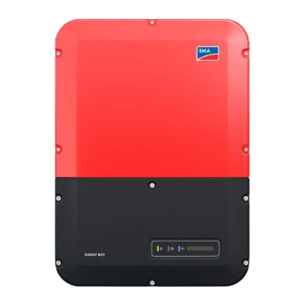
- Page 3 SMA POWER+ PARTS LIST SMA Sunny Boy Inverter Additional Gateway Shutdown TS4-R-S Part # SBx.x-1SP-US-40 Part # 150-00000-50 Part # 476-00240-00 TS4-S Rooftop Communication Kit Optimization TS4-R-O Part # ROOFCOMMKIT-P1-US Part # 471-00252-10 TS4 FKT Field Key Tool Part # 400-94000-10...
- Page 4 SMA POWER+ ROOFTOP COMMUNICATION KIT (WHAT’S IN THE BOX) DIN RAIL, SCREWS, and INSTALLATION LABELS and GUIDE ETHERNET CABLE MANUAL CLOUD CONNECT GATEWAY POWER SUPPLY SCREWDRIVER ADVANCE (CCA) and ANTENNA INSULATING SLEEVE...
- Page 5 SMA POWER+ ROOFTOP COMMUNICATION KIT LABELS NOTE This label is NEC 2014 compliant LABELS and GUIDE Do not use this label...
- Page 6 SMA POWER+ ROOFTOP COMMUNICATION KIT LABELS NOTE Labels for NEC 2017 For more information pertaining to compliance will have to be NEC 2017 labeling requirements obtained separately please view the poster listed below from HellermanTyton Image Source: www.HellermanTyton.com...
-
Page 7: Installation Overview
SMA POWER+ INSTALLATION OVERVIEW INSTALLATION OVERVIEW SMA Solar Technology AG 3.13.17 R. Raxter... - Page 8 SMA POWER+ CCA INSTALLATION OVERVIEW...
- Page 9 SMA POWER+ STEPS IN THE INVERTER Install din rail Attach antenna Connect CCA to din rail...
- Page 10 SMA POWER+ STEPS IN THE INVERTER Connect the power supply line to the power supply unit Connect the output of the power supply unit Unplug power supply terminal block from the CCA...
- Page 11 SMA POWER+ STEPS IN THE INVERTER Connect the positive and negative conductors to the terminal block Plug the power supply terminal block into the CCA. Mount the power supply unit on the din rail.
- Page 12 SMA POWER+ STEPS IN THE INVERTER Plug one end of the network cable into the network port B of the communication assembly Plug the other end of the network cable into the network port at the bottom of the CCA...
- Page 13 SMA POWER+ STEPS IN THE INVERTER Unplug gateway terminal block from the CCA. Connect the conductors to the terminal point of the terminal block Plug the gateway terminal block into the CCA Attach the conductor to the communication assembly using a zip tie.
- Page 14 SMA POWER+ INSTALLATION OVERVIEW (E)CLOUD CONNECT ADVANCE (CCA) and ANTENNA (B) 24V DC POWER CONNECTION (D) POWER SUPPLY (C) DIN RAIL (F) 120V AC POWER (H) RS485 FROM GATEWAY...
- Page 15 SMA POWER+ STEPS IN THE INVERTER Place the insulating hose over the AC conductors. Insert a flat-blade screwdriver into the actuation shaft (rectangular opening), then insert the connector into the terminal point (round openings). Ensure the conductors are plugged into the terminal points...
- Page 16 SMA POWER+ STEPS CONNECTING THE TS4-R DEVICE Clip the SMA TS4R-S/O to the PV Module...
- Page 17 SMA POWER+ STEPS CONNECTING THE TS4-R DEVICE Clip the SMA TS4R-S/O to the PV Module...
- Page 18 THE TS4-R DEVICE Connect the Module leads to the SMA TS4R-S/O – Connect the Female Negative module lead to the Male input of the SMA TS4R-S/O – Connect the Male Positive module lead to the Female input of the SMA TS4R-...
- Page 19 THE TS4-R DEVICE Connect the Module leads to the SMA TS4R-S/O – Connect the Female Negative module lead to the Male input of the SMA TS4R-S/O – Connect the Male Positive module lead to the Female input of the SMA TS4R-...
- Page 20 SMA POWER+ STEPS CONNECTING THE TS4-R DEVICE Then wire in series as normal...
- Page 21 SMA POWER+ STEPS CONNECTING THE TS4-R DEVICE Then wire in series as normal...
- Page 22 SMA POWER+ STEPS CONNECTING THE TS4-R DEVICE Then wire in series as normal...
- Page 23 SMA POWER+ STEPS CONNECTING THE TS4-R DEVICE Then wire in series as normal...
- Page 24 SMA POWER+ STEPS GATEWAY TO CCA One CCA for up to (3) Gateways Gateway located on the roof within array located in the inverter...
- Page 25 SMA POWER+ STEPS GATEWAY TO CCA One CCA for up to (3) Gateways Gateway(s) located on the roof within each array located in the inverter...
- Page 26 SMA POWER+ STEPS CONNECTING THE GATEWAY Radius 30’- to 50’ Gateway...
-
Page 27: Any Questions
THANK YOU! ANY QUESTIONS? 05.05.2017...
Need help?
Do you have a question about the POWER+ and is the answer not in the manual?
Questions and answers