Table of Contents
Advertisement
Quick Links
Advertisement
Table of Contents

Subscribe to Our Youtube Channel
Related Manuals for NI RMC-8355


Summary of Contents for NI RMC-8355
- Page 1 NI RMC-8355 User Manual NI RMC-8355 User Manual September 2012 373693B-01...
- Page 2 Worldwide Technical Support and Product Information ni.com Worldwide Offices Visit ni.com/niglobal to access the branch office Web sites, which provide up-to-date contact information, support phone numbers, email addresses, and current events. National Instruments Corporate Headquarters 11500 North Mopac Expressway Austin, Texas 78759-3504 USA Tel: 512 683 0100...
- Page 3 Warranty The NI RMC-8355 is warranted against defects in materials and workmanship for a period of one year from the date of shipment, as evidenced by receipts or other documentation. National Instruments will, at its option, repair or replace equipment that proves to be defective during the warranty period.
- Page 4 THE USER OR APPLICATION DESIGNER MUST TAKE REASONABLY PRUDENT STEPS TO PROTECT AGAINST SYSTEM FAILURES, INCLUDING BUT NOT LIMITED TO BACK-UP OR SHUT DOWN MECHANISMS. BECAUSE EACH END-USER SYSTEM IS CUSTOMIZED AND DIFFERS FROM NATIONAL INSTRUMENTS' TESTING PLATFORMS AND BECAUSE A USER OR APPLICATION DESIGNER MAY USE NATIONAL INSTRUMENTS PRODUCTS IN COMBINATION WITH OTHER PRODUCTS IN A MANNER NOT EVALUATED OR CONTEMPLATED BY NATIONAL INSTRUMENTS, THE USER OR APPLICATION DESIGNER IS ULTIMATELY RESPONSIBLE FOR VERIFYING AND VALIDATING THE SUITABILITY OF NATIONAL INSTRUMENTS PRODUCTS WHENEVER...
- Page 5 The Declaration of Conformity (DoC) contains important EMC compliance information and instructions for the user or installer. To obtain the DoC for this product, visit , search by model number or product line, ni.com/certification and click the appropriate link in the Certification column.
-
Page 6: Table Of Contents
Contents About This Manual Conventions ........................xi Related Documentation....................xii Chapter 1 Getting Started Unpacking ........................1-1 What You Need to Get Started ..................1-1 NI RMC-8355 Overview ....................1-2 Key Features ........................1-2 Mainboard Features ..................1-2 CPU....................1-2 Chipset ....................1-2 Memory .....................1-3 Slots....................1-3 Video....................1-3 HDD ....................1-3 DVD-R/W ..................1-3... - Page 7 Boot Device Priority ................. 2-32 Removable Drives ................2-32 CD/DVD Drives ................2-32 USB Drives..................2-33 Network Drives................. 2-33 Exit Options ....................2-33 Save Changes and Exit ..............2-33 Discard Changes and Exit..............2-34 NI RMC-8355 User Manual viii ni.com...
- Page 8 Universal Serial Bus ..................3-3 Serial........................3-4 VGA ........................3-5 Ethernet......................3-7 MXI-Express Connectors ....................3-8 Chapter 4 Common Configuration Questions General Questions......................4-1 Boot Options ........................4-2 Chassis Configuration....................4-2 Upgrade Information......................4-3 Chapter 5 Troubleshooting Appendix A Specifications Appendix B Hardware Configuration © National Instruments NI RMC-8355 User Manual...
- Page 9 Contents Appendix C Intel SATA RAID Utility for Intel ICH10R Appendix D Technical Support and Professional Services Glossary Index NI RMC-8355 User Manual ni.com...
-
Page 10: About This Manual
About This Manual The NI RMC-8355 User Manual contains information about installing, configuring, using, and maintaining the NI RMC-8355. Conventions The following conventions appear in this manual: » The » symbol leads you through nested menu items and dialog box options to a final action. -
Page 11: Related Documentation
• ANSI/IEEE Standard 1014-1987, IEEE Standard for a Versatile Backplane Bus: VMEbus • ANSI/VITA 1-1994, VME64 • NI-VISA User Manual • NI-VISA Programmer Reference Manual • Read Me First: Safety and Electromagnetic Compatibility, National Instruments NI RMC-8355 User Manual ni.com... -
Page 12: Getting Started
Getting Started This chapter describes the key features of the NI RMC-8355 and lists the kit contents and optional equipment you can order from National Instruments. Unpacking Carefully inspect the shipping container and the NI RMC-8355 for damage. Check for visible damage to the metal work. Check to make sure all hardware and switches are undamaged. -
Page 13: Ni Rmc-8355 Overview
48 GB of RDIMM ECC memory per processor. Key Features The NI RMC-8355 offers the performance of a high-end PC in a compact 1U rack-mountable form factor for controlling a PXI or PXI Express system using a National Instruments remote controller. -
Page 14: Memory
• Onboard I/O • PS/2 keyboard port • PS/2 mouse port • Serial port • VGA port • Two USB 2.0 ports (rear) • Two USB 2.0 ports (front) • Two RJ-45 ports © National Instruments NI RMC-8355 User Manual... -
Page 15: Power Supply
HDD indicator • System temp (overheat) and fan (fail) warning indicator System Management • Monitoring for CPU and chassis environment • CPU thermal trip support • +5 V standby alert LED • Fan speed control NI RMC-8355 User Manual ni.com... -
Page 16: Ni Rmc-8355 Description
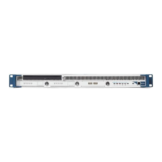
Chapter 1 Getting Started NI RMC-8355 Description Figure 1-1 shows the key features of the NI RMC-8355 front panel. For detailed information about the NI RMC-8355 rear panel, refer to Chapter 3, Information. 1 DVD R/W Drive 7 Power Shuttle 2 Indicator... -
Page 17: Upgrade/Optional Equipment
Chapter 1 Getting Started Upgrade/Optional Equipment Memory Upgrades You can upgrade the NI RMC-8355 memory to a maximum of 96 GB (48 GB per processor). Note A 32-bit operating system such as Windows XP Pro addresses a maximum of 4 GB. -
Page 18: National Instruments Software
NI-DAQmx provides an extensive library of functions you can call from your application development environment or interactive environment, such as NI Signal Express. These functions provide an intuitive API for National Instruments multifunction DAQ products. Features include analog © National Instruments... - Page 19 NI switches, DMMs, high-speed DIO, high-speed digitizers, and sources each have customized drivers for high-end modular instrumentation systems. RF applications leverage two drivers, NI-RFSG and NI-RFSA, and dynamic signal acquisition is available through NI-DAQmx. For more information, visit ni.com/...
-
Page 20: Installation And Bios Setup
Installation and BIOS Setup This chapter describes how to install, configure, and use the NI RMC-8355. Before connecting the NI RMC-8355 to a power source, read this chapter and the Read Me First: Safety and Electromagnetic Compatibility document included with your NI RMC-8355. -
Page 21: Chassis Cooling Considerations
Air enters through the front of the chassis and exits through the fans on the rear of the chassis. Place the NI RMC-8355 on a bench top or in an instrument rack so that the fans (air outlets) and the air inlet apertures in the front and rear of the chassis have adequate ventilation. -
Page 22: Installation
DC power source. Power on the NI RMC-8355. Verify that the NI RMC-8355 boots. If it does not boot, refer to the What if the NI RMC-8355 does not boot? section of Chapter 5, Troubleshooting. -
Page 23: Cable Retention Bracket
The NI RMC-8355 also includes a grounding screw (8-32 thread size nut) on the Note back of the chassis. (The nut is not supplied with the NI RMC-8355.) NI RMC-8355 User Manual ni.com... -
Page 24: Connecting To Power Source
Main tab at the top of the screen. The Main BIOS setup screen is shown below. (The processor and memory values in the image below may not accurately reflect your system configuration.) © National Instruments NI RMC-8355 User Manual... -
Page 25: System Overview
This item displays the BIOS revision used in your system. Build Date This item displays the date when this BIOS was completed. Processor The AMI BIOS automatically displays the status of the processor in your system. NI RMC-8355 User Manual ni.com... -
Page 26: System Memory
This item displays the system’s available memory size. Advanced Setup Configurations Use the arrow keys to select Boot Setup and press <Enter> to access the submenu items. The Advanced BIOS setup screen is shown below. © National Instruments NI RMC-8355 User Manual... -
Page 27: Boot Features
If this item is set to Disabled, the ROM BIOS of the host adaptors does not capture Interrupt 19, and the drives attached to these adaptors do not function as bootable devices. The options are Enabled and Disabled. NI RMC-8355 User Manual ni.com... -
Page 28: Power Configuration
If set to Enabled, the hardware prefetcher prefetches streams of data and instructions from the main memory to the L2 cache forward or backward to improve CPU performance. The options are Disabled and Enabled. Available when the CPU supports this option. © National Instruments NI RMC-8355 User Manual... - Page 29 If you change this setting, you must power off and restart the system for the change to take effect. Refer to the Intel Web site ( ) for detailed information. intel.com Available when the CPU supports this option. NI RMC-8355 User Manual 2-10 ni.com...
- Page 30 Intel AES-NI If this feature is set to Enabled, Intel AES-NI adds new encryption features to help accelerate AES software application, providing code authorization and signature verification to improve system performance. The default is Disabled. (Refer to the Intel ( ) and Microsoft intel.com...
-
Page 31: Advanced Chipset Control
Advanced Chipset Control The items included in the Advanced Settings submenu are listed below: CPU Bridge Configuration CPU Revision This item displays the CPU revision number. Current QPI Frequency This item displays current QPI frequency. NI RMC-8355 User Manual 2-12 ni.com... - Page 32 QPI L0s and L1 Select Enabled to set QPI power to a lower state. The motherboard automatically selects L0s and L1. The options are Disabled and Enabled. Available for the Intel Xeon 5600 platform only. © National Instruments 2-13 NI RMC-8355 User Manual...
-
Page 33: North Bridge Configuration
Available options are Disabled and Enabled. North Bridge Configuration Use this feature to configure Intel IOH settings. NB Revision This item indicates the North Bridge chipset revision number. NI RMC-8355 User Manual 2-14 ni.com... - Page 34 128 B. Other boards have a payload size of 256 B, which inhibits coalesce support. Refer to your add-on board documentation for the desired setting. The options are 256B and 128B. © National Instruments 2-15 NI RMC-8355 User Manual...
-
Page 35: South Bridge Configuration
This feature displays the current USB controller on the motherboard. USB 2.0 Controller Mode Use this setting to select the USB 2.0 controller mode. The options are Hi-Speed (480 Mbps) and Full Speed (12 Mbps). Available when the USB Functions item is disabled. NI RMC-8355 User Manual 2-16 ni.com... -
Page 36: Ide/Sata Configuration
SATA#2 Configuration Selecting Enhanced sets SATA#2 to native SATA mode. The options are Disabled and Enhanced. Available when RAID is selected. Available when AHCI is selected. Available when IDE is selected. © National Instruments 2-17 NI RMC-8355 User Manual... - Page 37 The options are Auto, 0, 1, 2, 3, and 4. Select Auto to allow the AMI BIOS to detect the PIO mode automatically. Use this value if you cannot determine the IDE disk drive support. NI RMC-8355 User Manual 2-18 ni.com...
- Page 38 Ultra DMA 0 16.6 Mbytes/s UDMA 1 Ultra DMA 1 25 Mbytes/s UDMA 2 Ultra DMA 2 33.3 Mbytes/s UDMA 3 Ultra DMA 3 44.4 Mbytes/s UDMA 4 Ultra DMA 4 66.6 Mbytes/s © National Instruments 2-19 NI RMC-8355 User Manual...
-
Page 39: Pci/Pnp Configuration
32, 64, 96, 128, 160, 192, 224, and 248. PCI IDE Bus Master When this feature is enabled, the BIOS uses PCI bus mastering for reading/writing to IDE drives. The options are Disabled and Enabled. NI RMC-8355 User Manual 2-20 ni.com... -
Page 40: Super Io Device Configuration
Select Disabled to prevent the serial port from accessing any system resources. When this option is set to Disabled, the serial port physically becomes unavailable. Select 3F8/IRQ4 to allow © National Instruments 2-21 NI RMC-8355 User Manual... -
Page 41: Remote Access Configuration
Note Some operating systems may not support this setting. Select Boot Loader to keep console redirection active during POST and when the Boot Loader is booting. The options are Disabled, Boot Loader, and Always. NI RMC-8355 User Manual 2-22 ni.com... -
Page 42: Hardware Health Event Monitoring
5 ºC above the threshold temperature, as the CPU manufacturer predefines, to give the CPU and system fans additional time needed for CPU and system cooling. For both alarms, take immediate action as described below. © National Instruments 2-23 NI RMC-8355 User Manual... - Page 43 CPU temperature tolerance has been reached or exceeded and may activate an overheat alarm. User intervention: If the system buzzer and Overheat LED has activated, take action immediately by checking the system fans, chassis ventilation, and room temperature to correct any problems. NI RMC-8355 User Manual 2-24 ni.com...
-
Page 44: Acpi Configuration
CPU1 DIMM, CPU2 DIMM, 5 V, 5 VSB, 12 V, –12 V, 3.3 Vcc, 3.3 VSB, VBAT, and Vtt. ACPI Configuration Use this feature to configure Advanced Configuration and Power Interface (ACPI) power management settings for your system. © National Instruments 2-25 NI RMC-8355 User Manual... - Page 45 ) for acpi.info further explanation. NUMA Support Select Enabled to use the Non-Uniform Memory Access feature to improve CPU performance. The options are Disabled, Enabled, and NUMA for SLES 11 (SUSE Linux Enterprise Server 11). NI RMC-8355 User Manual 2-26 ni.com...
-
Page 46: Ipmi Configuration (Not Supported)
SEL record ID • SEL record Type • Event timestamp • Generator ID • Event message format version • Event sensor type • Event sensor number • Event directory type • Event data © National Instruments 2-27 NI RMC-8355 User Manual... -
Page 47: Set Lan Configuration
DHCP mentioned in the other option. The options are DHCP and Static. IP Address The BIOS automatically enters the IP address of this machine; however, it may be overwriiten. IP addresses are six two-digit hexadecimal numbers. NI RMC-8355 User Manual 2-28 ni.com... -
Page 48: Event Log Configuration
Use this option to enable PCI Express error (PERR) logging. The options are Yes and No. Memory Error Log Use this option to enable memory error logging. The options are Yes and No. © National Instruments 2-29 NI RMC-8355 User Manual... -
Page 49: Security Settings
This item indicates whether a user password has been entered for the system. Not Installed means that a user password has not been used. Change Supervisor Password Select this feature and press <Enter> to access the Security menu, and then enter a new supervisor password. NI RMC-8355 User Manual 2-30 ni.com... -
Page 50: User Access Level
This item allows you to check a password after it has been entered. The options are Setup and Always. Available when a supervisor password is set. Available only when a user password is set. © National Instruments 2-31 NI RMC-8355 User Manual... -
Page 51: Boot Configuration
Use this feature to specify the boot sequence from available removable drives. The settings are 1st boot device, 2nd boot device, and Disabled. CD/DVD Drives Use this feature to specify the boot sequence from available CD/DVD drives. NI RMC-8355 User Manual 2-32 ni.com... -
Page 52: Usb Drives
BIOS Setup Utility and reboot the computer so that the new system configuration parameters can take effect. Select Save Changes and Exit from the Exit menu and press <Enter>. © National Instruments 2-33 NI RMC-8355 User Manual... -
Page 53: Discard Changes And Exit
Table 2-3. BIOS Error Beep Codes Beep Code Error Message Description One beep Refresh Circuits have been reset. (Ready to power up.) Five short beeps Memory error No memory is detected in and one long beep the system. NI RMC-8355 User Manual 2-34 ni.com... -
Page 54: Os Reinstallation And Recovery
<F4> when video first appears during the boot process. • The NI RMC-8355 also ships with an OS recovery CD/DVD you can use to reinstall your operating system onto your hard drive. If you need to reinstall your operating system, you can use the included OS recovery CD/DVD. -
Page 55: Cleaning
Rack Mounting Caution When mounting the equipment in the rack, do not create a hazardous condition due to uneven mechanical loading. The NI RMC-8355 rack mounting hardware includes: • One pair of inner slides to be installed on the chassis. •... -
Page 56: Installing The Inner Slides
Chapter 2 Installation and BIOS Setup Installing the Inner Slides Install the inner slides to the NI RMC-8355 as shown in Figure 2-2. 1 Retaining Screw (x14) 2 Inner Slide Figure 2-2. Installing Inner Slides © National Instruments 2-37 NI RMC-8355 User Manual... -
Page 57: Installing The Slide Mounting Brackets In The Rack
Install the slide mounting brackets in the rack as shown in Figure 2-3. 1 Retaining Screw (x4) 3 Washer (x8) 2 Slide Mounting Bracket (x4) 4 Nut (x4) Figure 2-3. Installing Slide Mounting Brackets in Rack NI RMC-8355 User Manual 2-38 ni.com... -
Page 58: Installing The Outer Slides In The Rack
Installing the Outer Slides in the Rack Install the outer slides in the rack as shown in Figure 2-4. 1 Nut (x6) 2 Outer Slide 3 Retaining Screw (x6) Figure 2-4. Installing Outer Slides in Rack © National Instruments 2-39 NI RMC-8355 User Manual... -
Page 59: Installing The Chassis Into The Rack
Installing the Chassis into the Rack Push the inner slides, attached to the chassis, into the grooves of the outer slides in the rack and slide the NI RMC-8355 into the rack, as shown in Figure 2-5. Figure 2-5. Installing NI RMC-8355 in Rack... -
Page 60: I/O Information
I/O Information This chapter describes the NI RMC-8355 I/O connectors. Rear Panel Connectors Table 3-1 lists various peripherals and their corresponding NI RMC-8355 external connectors, bus interfaces, and functions. Table 3-1. NI RMC-8355 Peripherals Overview Peripheral External Connector Description Keyboard... -
Page 61: Ps/2
Figure 3-1. NI RMC-8355 Rear Panel Layout PS/2 Figure 3-2 shows the location and pinouts for the PS/2 keyboard and mouse connectors on the NI RMC-8355. Table 3-2 lists and describes the PS/2 connector signals. PS/2 Figure 3-2. PS/2 Connector Location and Pinout NI RMC-8355 User Manual ni.com... -
Page 62: Universal Serial Bus
Clock Mouse Universal Serial Bus Figure 3-3 shows the location and pinouts for the Universal Serial Bus (USB) connectors on the NI RMC-8355. Table 3-3 lists and describes the USB connector signals. Figure 3-3. USB Connector Location and Pinout Table 3-3. USB Connector Signals... -
Page 63: Serial
I/O Information Serial Figure 3-4 shows the location and pinouts for the serial connector on the NI RMC-8355. Table 3-4 lists and describes the serial connector signal. Serial Figure 3-4. Serial Connector Location and Pinout Table 3-4. Serial Connector Signals... -
Page 64: Vga
Chapter 3 I/O Information Figure 3-5 shows the location and pinouts for the VGA connector on the NI RMC-8355. Table 3-5 lists and describes the VGA connector signals. Figure 3-5. VGA Connector Location and Pinout © National Instruments NI RMC-8355 User Manual... - Page 65 Chapter 3 I/O Information Table 3-5. VGA Connector Signals Signal Name Signal Description Green Blue Not Connected Ground Ground Ground Ground Ground Not Connected Serial Data HSync Horizontal Sync VSync Vertical Sync Serial Clock NI RMC-8355 User Manual ni.com...
-
Page 66: Ethernet
Chapter 3 I/O Information Ethernet Figure 3-6 shows the location and pinouts for the Ethernet connectors on the NI RMC-8355. Table 3-6 lists and describes the Ethernet connector signals. Ethernet Figure 3-6. Ethernet Connector Location and Pinout Table 3-6. Ethernet Connector Signals... -
Page 67: Mxi-Express Connectors
Note The NI RMC-8355 BIOS supports only 188 PCI buses by default. For large multichassis systems requiring more than 188 PCI buses, use the NI MXI-Express BIOS Compatibility Software to work around this limitation on Windows. At this time, there is no workaround available for systems running LabVIEW RT. -
Page 68: Common Configuration Questions
The power indicator lights when the main power is turned on. The LAN status LEDs flash to when there is activity on LAN1 and LAN2. The hard drive LED lights when there is hard drive activity on the NI RMC-8355. For more information, refer to Figure 1-1, Front View of the NI RMC-8355. -
Page 69: Boot Options
There are some limitations when booting from a USB device. Windows XP can be installed from a USB CD-ROM, but earlier versions of Windows cannot. The NI RMC-8355 BIOS configures the USB devices so that they will work in a DOS environment. -
Page 70: Upgrade Information
(PXI System pxisys.ini Initialization). The NI RMC-8355 uses MAX to generate the pxisys.ini file from the file. chassis.ini Device drivers and other utility software read the file to pxisys.ini... - Page 71 Chapter 4 Common Configuration Questions What upgrade options are available for the RMC-8355? Table 4-1 lists the available upgrade options. Table 4-1. NI RMC-8355 Upgrade Options Orderable P/N Description 782116-01 Spare optical drive for NI RMC-8355 782117-01 Spare 250 GB SSD and drive bay for...
-
Page 72: Troubleshooting
Chapter 1, Getting Started, for more information.) Things to Try: • Make sure the NI RMC-8355 is plugged in to a working power source. • Remove the power supply and reinsert it. • Remove any nonessential cables or devices. •... - Page 73 • Remove memory from unsupported slots. My NI RMC-8355 boots fine until I get to Windows, at which point I cannot read the screen. This may include garbled output, white screen, black screen, or an out of synch message from the monitor.
-
Page 74: Appendix A Specifications
Specifications This appendix lists the NI RMC-8355 electrical, mechanical, and environmental specifications. Electrical AC Input Input voltage range......... 100–240 VAC Operating voltage range ......90–264 VAC Input frequency ........50/60 Hz Operating frequency range..... 47–63 Hz Current rating ......... 4–2 A max (480 W max single power supply) Power disconnect ........ - Page 75 Appendix A Specifications Using the NI RMC-8355 in a manner not described in this document may impair Caution the protection the NI RMC-8355 provides. Mainboard Socket .............LGA 1366 (dual socket) Chipset ............Intel 5520 chipset Memory slots ..........Twelve 240-pin DIMM DDR3...
- Page 76 Standard shipping memory is 3 GB per CPU (3 × 1 GB). Mechanical Overall dimensions (standard chassis) Height..........1U Width ..........432 mm (17.0 in.) Depth..........533 mm (21.0 in.) Weight ............ 8.1 kg (17.8 lbs) © National Instruments NI RMC-8355 User Manual...
- Page 77 0.0002 g 350–500 –3 dB/octave 0.00014 g Total g = 0.31 Non-Operational Random Frequency (Hz) Vibration Level 5–100 0.02 g 100–200 –3 dB/octave 200–350 0.01 g 350–500 –3 dB/octave 0.007 g Total g = 2.46 NI RMC-8355 User Manual ni.com...
- Page 78 IEC-60068-2-1 and IEC-60068-2-2.) Relative humidity (tested in accordance with IEC-60068-2-56) Operating ........10 to 90% noncondensing Nonoperational (storage) ....5 to 95% noncondensing Operating location........Indoor use only Maximum altitude ........3,000 m © National Instruments NI RMC-8355 User Manual...
- Page 79 FCC 47 CFR Part 15B: Class A emissions • ICES-001: Class A emissions Note For the standards applied to assess the EMC of this product, refer to the Online Product Certification section. For EMC compliance, operate this device with shielded cabling. Note NI RMC-8355 User Manual ni.com...
- Page 80 Certification column. Environmental Management NI is committed to designing and manufacturing products in an environmentally responsible manner. NI recognizes that eliminating certain hazardous substances from our products is beneficial to the environment and to NI customers.
- Page 81 Instruments service representative. For more information about compliance with the EU Battery Directive 2006/66/EC about Batteries and Accumulators and Waste Batteries and Accumulators, visit ni.com/environment/batterydirective National Instruments (RoHS) National Instruments RoHS ni.com/environment/rohs_china (For information about China RoHS compliance, go to ni.com/environment/rohs_china NI RMC-8355 User Manual ni.com...
-
Page 82: Appendix B Hardware Configuration
Hardware Configuration This appendix describes how to configure and upgrade the NI RMC-8355 hardware. Caution: Hazardous Voltage Area No user (operator) serviceable parts are inside the NI RMC-8355. The hardware configuration and upgrade procedures described in this appendix must be performed only by a qualified service technician. - Page 83 Appendix B Hardware Configuration Figure B-1 shows the key features of the NI RMC-8355 mainboard. Fan8 (CPU1Fan) P1-DIMM3A P1-DIMM3B P1-DIMM2A P1-DIMM2B P1-DIMM1A JPI2C CPU2 P1-DIMM1B Fan1 Fan2 Battery X8DTU/-F JBAT1 CPU1 Rev. 2.01 Buzzer Fan3 P2-DIMM1B P2-DIMM1A P2-DIMM2B P2-DIMM2A LAN CTRL...
- Page 84 System/CPU fan headers (fans 7–8 are CPU fans) IPMB IPMB I C header (for an IPMI card) (not supported) Speaker/power LED header (pins 4–7 are for the speaker) Front panel control connector Chassis intrusion header JOH1 Overheat LED header © National Instruments NI RMC-8355 User Manual...
- Page 85 (refer to caution above) USB0/1 Universal serial bus (USB) ports (back panel) F/P USB 2/3, 4/5, 6, 7 Front panel-accessible USB headers Video port Table B-3. LED Descriptions Description Onboard standby PWR warning LED indicator Unit identifier LED NI RMC-8355 User Manual ni.com...
- Page 86 NIC1 (Activity) LED NIC2 (Link) LED NIC2 (Activity) LED Blue+ (Overheat/Fan Fail/ Red+ (Blue LED_ PWR Fail/Blue_UID LED) Cathode_UID) PWR Fail LED 3.3 V Ground Reset Button Ground Power Button Figure B-2. JF1 Header Pins © National Instruments NI RMC-8355 User Manual...
- Page 87 UID switch connection. The front UID switch works in conjunction with the UID LED on pins 7–8. Refer to Table B-6 for pin definitions. Table B-6. HDD LED/UID Pin Definitions Definition UID switch/3.3 V HDD active NI RMC-8355 User Manual ni.com...
- Page 88 LED by default. Refer to Tables B-9 and B-10 for pin definitions and LED statuses. Table B-9. Overheat/Fan Fail/Power Fail/Blue_UID LED Pin Definitions Definition Blue LED cathode (UID) Overheat/fan fail/power fail/ UID LED © National Instruments NI RMC-8355 User Manual...
- Page 89 The reset button connection is on pins 3 and 4 of JF1. Attach the connection to a hardware reset switch on the computer case. Refer to Table B-12 for pin definitions. Table B-12. Reset Button Pin Definitions Definition Reset Ground NI RMC-8355 User Manual ni.com...
- Page 90 To power off: power is turned off immediately PWR_Off set to 4-second suspend To power on: power is turned on immediately To power off: short both pins for 4 seconds or longer to turn off power © National Instruments NI RMC-8355 User Manual...
- Page 91 20-pin and two 8-pin power connectors. Be sure to connect these power connectors to the 20-pin and two 8-pin power connectors on your motherboard for adequate power supply to your system. Failure to do so voids the manufacturer warranty on your power supply and motherboard. NI RMC-8355 User Manual B-10 ni.com...
- Page 92 –5 Vdc White +5 Vdc VSB Purple +5 Vdc standby voltage +12 Vdc Yellow +5 Vdc Table B-16. 12 V 8-Pin Power Connector Pin Definitions Pins Definition 1–4 Ground 5–8 +12 V © National Instruments B-11 NI RMC-8355 User Manual...
- Page 93 Table B-17. Universal I/O Power Connector Pin Definitions Definition Definition P3V3 P3V3 P3V3 P3V3 P3V3 P3V3 P3V3 P3V3 P3V3 P3V3 N12V P3V3 P3V3 standby P3V3 P3V3 standby P12V Ground P12V Ground P12V Ground P12V NI RMC-8355 User Manual B-12 ni.com...
- Page 94 Intrusion input Ground Fan Headers (Fan1–Fan8) The NI RMC-8355 has six chassis/system fan headers (Fan1 to Fan6) and two CPU fan headers (Fan7/Fan8) on the motherboard. These 4-pin fan headers are backward compatible with the traditional 3-pin fans. However, fan speed control is available for 4-pin fans only. A hardware monitoring setting in the BIOS controls the fan speeds.
- Page 95 (4–7) are for use with an external speaker. To use the onboard speaker, close pins 6–7 with a jumper. Figure B-8. Speaker/Power LED Header (JD1) Table B-20. Speaker/Power LED Pin Definitions Pins Definition 1–3 Power LED 4–7 External speaker 6–7 Internal speaker NI RMC-8355 User Manual B-14 ni.com...
- Page 96 The JOH1 header connects an LED indicator to warn of chassis overheating or fan failure. This LED blinks when a fan failure occurs. Refer to Table B-22 for pin definitions. Figure B-10. Overheat/Fan Fail LED Header (JOH1) © National Instruments B-15 NI RMC-8355 User Manual...
- Page 97 Refer to Table B-24 for pin definitions. Figure B-11. Power SMB (I C) Connector (JPI Table B-24. Power SMB (I C) Pin Definitions Definition Clock Data Power fail Ground +3.3 V NI RMC-8355 User Manual B-16 ni.com...
- Page 98 JPL1 enables or disables GLAN port1/GLAN port2 on the motherboard. Refer to Table B-25 for jumper settings. The default setting is Enabled. Figure B-13. GLAN Enable/Disable Jumper (JPL1) Table B-25. IGLAN Enable/Disable Jumper Settings Pins Setting 1–2 Enabled (default) 2–3 Disabled © National Instruments B-17 NI RMC-8355 User Manual...
- Page 99 (NMI) signal for the application that hangs. Refer to Table B-26 for jumper settings. You also must enable watchdog in the BIOS. Figure B-15. Watchdog Enable/Disable Jumper (JWD) Table B-26. Watchdog Enable/Disable Jumper Settings Pins Definition 1–2 Reset (default) 2–3 Open Disabled NI RMC-8355 User Manual B-18 ni.com...
- Page 100 1 and 2 to enable VGA. Refer to Table B-28 for jumper settings. Figure B-17. VGA Enable Jumper (JPG1) Table B-28. VGA Enable Jumper Settings Pins Definition 1–2 Enabled (default) 2–3 Disabled © National Instruments B-19 NI RMC-8355 User Manual...
- Page 101 Figure B-18. GLAN LEDs (LAN1/LAN2) Table B-29. GLAN Activity Indicator LED Statuses Color Status Inactive Blinking yellow Active Table B-30. GLAN Link Indicator LED Statuses Color Status No connection or 10 Mbps Green 100 Mbps Amber 1 Gbps NI RMC-8355 User Manual B-20 ni.com...
- Page 102 These ports provide serial link signal transmission, which is faster than traditional parallel ATA. Refer to Table B-32 for pin definitions. Figure B-19. I-SATA Connector (JS1–JS6) Table B-32. Serial ATA Pin Definitions Definition Ground TX_P TX_N Ground © National Instruments B-21 NI RMC-8355 User Manual...
- Page 103 Memory upgrades are available from National Instruments under the following Note orderable part numbers: 1 × 1 GB DDR3 RAM for NI RMC-8355 (1 × 1 GB RDIMM) • 1 × 4 GB DDR3 RAM for NI RMC-8355 (1 × 4 GB RDIMM) •...
- Page 104 6 DIMMs P2 DIMM1A P2 DIMM1B P2 DIMM2A P2 DIMM2B P2 DIMM3A P2 DIMM3B Memory Population for Optimal Performance For a Motherboard with Two CPUs Installed CPU1 CPU2 Branch 0 Branch 1 Branch 3 Branch 0 Branch 1 Branch 3 6 DIMMs 12 DIMMs © National Instruments B-23 NI RMC-8355 User Manual...
- Page 105 Appendix B Hardware Configuration Memory Support The NI RMC-8355 supports up to 96 GB registered ECC DDR3 800 MHz/1066 MHz in 12 DIMMs. (Refer to for the ni.com recommended memory list.) Memory Support for the Motherboard with 5600 Processors Installed Memory speed support depends on the type of CPU used.
- Page 106 The 1333/1066 MHz QR RDIMMs run at 800 MHz (BIOS automatic downgrading). ‡ The 1333 MHz SR/DR RDIMMs run at 800 MHz (BIOS automatic downgrading). The 1333/1066 MHz SR/DR/QR RDIMMs run at 800 MHz (BIOS automatic downgrading). © National Instruments B-25 NI RMC-8355 User Manual...
- Page 107 PCI enumeration area 2 (if needed) (aligned on 512 MB 3.01 GB 256 MB boundary) VGA memory 16 MB 2.85 GB TSEG 1 MB 2.84 GB Memory available for the OS and other — 2.84 GB applications NI RMC-8355 User Manual B-26 ni.com...
- Page 108 Installing DDR Modules Follow these steps to install DDR modules: Press the cover release buttons on the top of the NI RMC-8355. Push the cover backward to remove it. Align the notch in the center of the DDR DIMM module with the key on the DIMM slot.
- Page 109 When the module is fully inserted, the plastic clip at each side of the slot automatically closes, as shown below. Replace the NI RMC-8355 cover by sliding the cover forward. Make sure the safety lock fits firmly. Removing DDR Modules Follow these steps to remove DDR modules: Open the plastic clips on both sides of the module.
- Page 110 Appendix B Hardware Configuration Upgrading and Replacing Hard Disk Drives Figure B-20 shows the NI RMC-8355 SATA connector locations. Fan8 (CPU1Fan) P1-DIMM3A P1-DIMM3B P1-DIMM2A P1-DIMM2B JPI2C P1-DIMM1A CPU2 P1-DIMM1B Fan1 Fan2 Battery X8DTU/-F JBAT1 CPU1 Rev. 2.01 Buzzer P2-DIMM1B Fan3...
- Page 111 Use the part numbers in Table B-38 to order a spare/upgrade hard drive. Table B-38. Hard Drive Part Numbers Part Number Description 782117-01 Spare 250 GB SSD and drive bay for NI RMC-8355 782314-01 Spare 500 GB HDD and drive bay for NI RMC-8355 NI RMC-8355 User Manual B-30 ni.com...
- Page 112 By doing so, a “mirror” of source data is created to enhance data security. To use RAID1, two or more hard drive disks are required, and the second drive must be the same size or larger than the first drive. © National Instruments NI RMC-8355 User Manual...
- Page 113 RAID0 and press <Enter>. Note Stripe size is 4–128 KB for RAID0. For a server, use a lower stripe size; for a multimedia system, use a higher stripe size. The default stripe size is 128 KB. NI RMC-8355 User Manual ni.com...
- Page 114 A master drive is the original drive containing the source files to be copied to the recovery drive. Follow these steps to create a recovery drive: Select Create RAID Volume from the main menu and press <Enter>. The Create Volume Menu screen appears. © National Instruments NI RMC-8355 User Manual...
- Page 115 <Del>. A warning message displays. At the Are you sure you want to delete this volume (Y/N) prompt, press <Y> to delete the RAID volume or <N> to return to the Delete Volume menu. NI RMC-8355 User Manual ni.com...
- Page 116 If a master disk is available, its RAID volume recovery support is enabled, and the recovery disk is disabled. Any change in steps 3 or 4 stops automatic synchronization between the master and recovery drives. Press <Esc> to return to the main menu. © National Instruments NI RMC-8355 User Manual...
- Page 117 Follow these steps to exit the Intel Matrix Storage Manager utility: From the main menu, select Exit and press <Enter>. A warning message appears. At the prompt, press <Y> to delete the drive or <N> to return to the main menu. NI RMC-8355 User Manual ni.com...
- Page 118 KnowledgeBase, product manuals, step-by-step troubleshooting wizards, thousands of example programs, tutorials, application notes, instrument drivers, and so on. Registered users also receive access to the NI Discussion Forums . NI Applications Engineers make sure every ni.com/forums question submitted online receives an answer.
- Page 119 NI office or visit ni.com/alliance You also can visit the Worldwide Offices section of ni.com/niglobal to access the branch office Web sites, which provide up-to-date contact information, support phone numbers, email addresses, and current events. NI RMC-8355 User Manual ni.com...
- Page 120 Analog-to-digital. Most often used as A/D converter. Alternating Current ACPI Advanced Configuration and Power Management Interface ANSI American National Standards Institute Application Programming Interface—A standardized set of subroutines or functions along with the parameters that a program can call. © National Instruments NI RMC-8355 User Manual...
- Page 121 Complementary Metal Oxide Semiconductor—A process used in making chips. Communications port Central Processing Unit Carrier Serving Area Digital-to-analog—Most often used as an abbreviation for a D/A converter (also known as DAC). Direct Current Double Data Rate DIMM Dual In-line Memory Module NI RMC-8355 User Manual ni.com...
- Page 122 Electronically Erasable Programmable Read Only Memory Electromagnetic Compatibility Electromagnetic Interference Enhanced Parallel Port Federal Communications Commission Gigabytes of memory GPIB General Purpose Interface Bus (IEEE 488) Hard Disk Drive Hertz; cycles per second © National Instruments NI RMC-8355 User Manual...
- Page 123 Liquid Crystal Display—A display technology using polarizing filters and liquid crystal cells. Light-emitting diode Measurement & Automation Explorer Megabytes of memory Multiprocessor Specification MTBF Mean Time Between Failure MTTR Mean Time to Repair Multisystem eXtension Interface NI RMC-8355 User Manual ni.com...
- Page 124 CompactPCI products. Random Access Memory—The computer’s primary workspace. Row Address Strobe Root Mean Squared Real Time Clock—An electronic circuit that maintains the time of day and also can provide timing signals for timesharing operations. © National Instruments NI RMC-8355 User Manual...
- Page 125 VISA Virtual Instrument Software Architecture—A single interface library for controlling GPIB, VXI, RS232, and other types of instruments. VISA has been standardized by the VXI Plug&Play Systems Alliance. Versa Module Eurocard VME eXtensions for Instrumentation NI RMC-8355 User Manual ni.com...
- Page 126 Glossary Watts Watchdog Timer © National Instruments NI RMC-8355 User Manual...
- Page 127 Current Memory Frequency for Add On ROM Display Mode, 2-8 CPU1/CPU2, 2-13 Adjacent Cache Line Prefetcher, 2-10 Current QPI Frequency, 2-12 Advanced Chipset Control, 2-12 Data Reuse Optimization, 2-10 Advanced setup menu, 2-7 © National Instruments NI RMC-8355 User Manual...
- Page 128 Power Button Function, 2-9 IOH PCI Express Max Payload Size, 2-15 power configuration, 2-9 IP Address, 2-28 Primary IDE Master/Slave, 2-18 IP Address Source, 2-28 Processor and Clock Options, 2-9 IPMI Configuration (X8DTU-F processor status, 2-6 Only), 2-27 NI RMC-8355 User Manual ni.com...
- Page 129 Status of BMC Working, 2-27 Subnet Mask, 2-29 Super IO Device Configuration, 2-21 C1 Auto Demotion, 2-12 Supervisor Password, 2-30 C1E Support, 2-12 System Date, 2-6 C3 Auto Demotion, 2-12 System Memory, 2-7 © National Instruments NI RMC-8355 User Manual...
- Page 130 3-3 electrical specifications, A-1 VGA connector and signals, 3-5 electromagnetic compatibility specifications, conventions used in the manual, xi cooling, air cooling of NI RMC-8355, 2-2 environmental management specifications, CPU Bridge Configuration, 2-12 CPU Overheat Alarm, 2-23 environmental specifications, A-5...
- Page 131 Index testing power up, 2-5 unpacking the NI RMC-8355, 1-1 Fan 1 ~ Fan 8 Reading, 2-25 installing NI RMC-8355, 2-1 fan headers (Fan1 to Fan8) instrument drivers (NI resources), D-1 pinout (figure), B-13 Intel AES-NI, 2-11 Fan Speed Control Modes, 2-25...
- Page 132 Ethernet, 3-7 Mac Address, 2-29 PS/2 connector and signals, 3-2 mainboard specifications, A-2 serial connector and signals, 3-4 maintenance of NI RMC-8355 Universal Serial Bus (USB) cleaning, exterior, 2-36 connector and signals, 3-3 Mark All Events as Read, 2-29 VGA, 3-5...
- Page 133 Primary IDE Master/Slave, 2-18 upgrading memory, B-22 Processor and Clock Options, 2-9 upgrading RAM, 4-3 processor status, 2-6 using with PXI chassis, 4-2 programming examples (NI resources), D-1 NI-DAQmx, 1-7 PS/2 NI-VISA, 1-8 connector and signals, 3-2 Non-RAID, resetting to, C-5...
- Page 134 Sredir Memory Display Delay, 2-23 Serial Port Mode, 2-22 SR-IOV Supported, 2-21 Serial Port Number, 2-22 Status of BMC Working, 2-27 Serial Port1 Address/Serial Port2 Subnet Mask, 2-29 Address, 2-21 Super IO Device Configuration, 2-21 Supervisor Password, 2-30 NI RMC-8355 User Manual ni.com...
- Page 135 Third IDE Master, 2-18 video, 3-1 Throttling—Closed Loop/Throttling—Open See also VGA Loop, 2-14 View BMC System Event Log, 2-27 training and certification (NI resources), D-1 View Event Log, 2-29 troubleshooting Voltage Monitoring, 2-25 controller does not boot, 5-1 VT-UTF8 Combo Key Support, 2-23...
Need help?
Do you have a question about the RMC-8355 and is the answer not in the manual?
Questions and answers