Table of Contents
Advertisement
VIESMANN
Installation and service instructions
for contractors
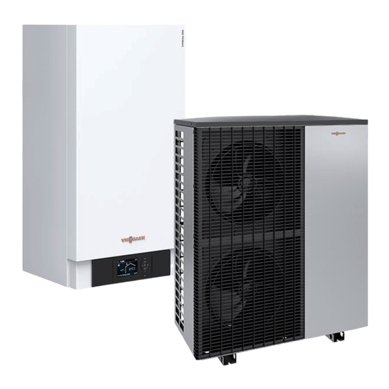
Vitocal 200-A
Type AWO(-M)/AWO(-M)-E 201.A
Air source heat pump, monoblock version for heating mode
Type AWO(-M)-E-AC 201.A
Air source heat pump, monoblock version for heating and cooling operation
VITOCAL 200-A
Please keep safe.
6150148 GB
11/2019
Advertisement
Table of Contents

Subscribe to Our Youtube Channel
Related Manuals for Viessmann VITOCAL 200-A Series


Summary of Contents for Viessmann VITOCAL 200-A Series
- Page 1 VIESMANN Installation and service instructions for contractors Vitocal 200-A Type AWO(-M)/AWO(-M)-E 201.A Air source heat pump, monoblock version for heating mode Type AWO(-M)-E-AC 201.A Air source heat pump, monoblock version for heating and cooling operation VITOCAL 200-A Please keep safe. 6150148 GB 11/2019...
-
Page 2: Safety Instructions
Safety instructions Safety instructions Please follow these safety instruc- tions closely to prevent accidents and material losses. Safety instructions explained Danger Note This symbol warns against the risk Details identified by the word "Note" of injury. contain additional information. Please note This symbol warns against the risk of material losses and environmen- tal pollution. - Page 3 Safety instructions Safety instructions (cont.) Safety instructions for working on the system Working on the system Please note Electronic assemblies can be dam- Isolate the system from the power sup- ■ aged by electrostatic discharge. ply, e.g. by removing the separate fuse Prior to commencing work, touch or by means of a mains isolator, and earthed objects such as heating or...
-
Page 4: Repair Work
Further measures before starting work Replace faulty components only on the refrigerant circuit with flammable with genuine Viessmann spare refrigerants (R32): parts. Remove all flammable materials and ■ Auxiliary components, spare and... - Page 5 Index Index 1. Information Disposal of packaging ................Symbols ....................Intended use ..................Product information ................System examples ................■ Spare parts lists .................. ■ 2. Preparing for installation Requirements for on-site connections ........... 10 Indoor unit ................... 10 ■ Outdoor unit ..................
- Page 6 Ω ■ Indoor unit: Viessmann NTC 20 k (orange marking) ......87 Ω ■ Indoor unit: Viessmann Pt500A (green marking) ........ 88 ■ Outdoor unit: Viessmann NTC 10 k (no marking) ......89 Ω ■ Checking the fuses ................89 6.
-
Page 7: Disposal Of Packaging
Information Disposal of packaging Please dispose of packaging waste in line with statu- tory regulations. Symbols The steps in connection with commissioning, inspec- Symbol Meaning tion and maintenance are found in the "Commission- Reference to other document containing ing, inspection and maintenance" section and identified further information as follows: Step in a diagram:... -
Page 8: Product Information
Information Intended use (cont.) Incorrect usage or operation of the appliance (e.g. the Note appliance being opened by the system user) is prohibi- The appliance is intended exclusively for domestic or ted and will result in an exclusion of liability. Incorrect semi-domestic use, i.e. - Page 9 Information Product information (cont.) System examples Available system examples: See www.viessmann- schemes.com. Spare parts lists Information about spare parts can be found at www.viessmann.com/etapp or in the Viessmann spare part app.
-
Page 10: Indoor Unit
Preparing for installation Requirements for on-site connections Indoor unit Fig. 1 Outdoor unit return (heating water outlet): G 1 Heating water flow G 1 (union nut DN 32, female ¼ ¼ (union nut DN 32, female thread) thread) Outdoor unit flow (heating water inlet): G 1 Cable entry for extra low voltage (ELV) leads ¼... -
Page 11: Requirements For On-Site Connections
Preparing for installation Requirements for on-site connections (cont.) Outdoor unit Outdoor unit with 1 fan 1109 Fig. 2 Outdoor unit flow (heating water outlet) G 1 Power cable inlet ¼ (union nut supplied, female thread) Modbus cable inlet for indoor/outdoor unit Outdoor unit return (heating water outlet) G 1 ¼... - Page 12 Preparing for installation Requirements for on-site connections (cont.) Outdoor unit with 2 fans 1109 Fig. 3 Outdoor unit flow (heating water outlet) G 1 Power cable inlet ¼ (union nut supplied, female thread) Modbus cable inlet for indoor/outdoor unit Outdoor unit return (heating water outlet) G 1 ¼...
-
Page 13: Installing The Outdoor Unit
Installation sequence Installing the outdoor unit Transport Please note Please note Impacts, compression and tensile loads can If the compressor in the outdoor unit is tilted too cause damage to the outside panels of the far, lubricant will enter the refrigerant circuit and appliance. -
Page 14: Installation Location
Installation sequence Installing the outdoor unit (cont.) Weight of outdoor units Heat pumps with outdoor unit 400 V Types Weight in kg Heat pumps with outdoor unit 230 V 201.A10 Types Weight in kg 201.A13 201.A04 201.A16 201.A06 201.A08 201.A10 201.A13 201.A16 Installation location... - Page 15 Installation sequence Installing the outdoor unit (cont.) Minimum clearances for 1 outdoor unit Outdoor unit with 1 fan 1000 Fig. 4 Air intake Air discharge ■ Line entry above ground level: 200 mm ≥ Line entry below ground level: ■ 900 mm ≥...
- Page 16 Installation sequence Installing the outdoor unit (cont.) Outdoor unit with 2 fans 1000 Fig. 5 Air intake Air discharge ■ Line entry above ground level: 200 mm ≥ Line entry below ground level: ■ 900 mm ≥ Minimum clearances for heat pump cascades (max. 5 outdoor units) Facing layout without partition wall Facing layout with partition wall >...
- Page 17 Installation sequence Installing the outdoor unit (cont.) Single row layout > 500 > 500 > 500 > 500 > 500 > 500 Fig. 8 Air intake Air discharge Floorstanding installation Foundations Fit the floor supports on 2 horizontal foundation strips. We recommend the construction of concrete founda- tions in accordance with the following diagram.
- Page 18 Installation sequence Installing the outdoor unit (cont.) For support for floorstanding installation 1100 Fig. 9 Frost protection for foundations (compacted Fixing points for support crushed stone, e.g. 0 to 32/56 mm); thickness of Use ground anchors with a tensile force of at least layer subject to local requirements and building 2.5 kN.
- Page 19 Installation sequence Installing the outdoor unit (cont.) For design casing with support Fig. 10 Frost protection for foundations (compacted Fixing points for support crushed stone, e.g. 0 to 32/56 mm); thickness of Use ground anchors with a tensile force of at least layer subject to local requirements and building 2.5 kN.
- Page 20 Installation sequence Installing the outdoor unit (cont.) Floorstanding installation with support: Line entry Floorstanding installation with support and design above ground level casing: Line entry above ground level 3000 3000 1100 Fig. 12 Fig. 11 Ground Pathway, patio Ground Hydraulic connection lines, indoor/outdoor unit Pathway, patio Indoor/outdoor unit Modbus cable and outdoor unit Hydraulic connection lines, indoor/outdoor unit...
- Page 21 Installation sequence Installing the outdoor unit (cont.) Floorstanding installation with support, line entry below ground level 3000 1100 Fig. 13 Ground Floorstanding installation connection set (accesso- Pathway, patio ries) Support for floorstanding installation (accessories) Hydraulic connection set (accessories) Openings in the base plate for free drainage of Foundation strip condensate: Frost protection for foundations (compacted...
- Page 22 Installation sequence Installing the outdoor unit (cont.) Floorstanding installation with support and design casing: Line entry below ground level 3000 Fig. 14 Ground Connection set, floorstanding installation (accesso- Pathway, patio ries) Hydraulic connection set (accessories) Design casing with support (accessories) Openings in the base plate for free drainage of Foundation strip condensate:...
-
Page 23: Wall Mounting
Installation sequence Installing the outdoor unit (cont.) Installing an outdoor unit on foundations Note We recommend letting condensate drain away freely (no condensate pipe). Fig. 15 Support for floorstanding installation (accessories) Gravel bed as condensate soakaway Concrete foundations (see technical guide) Only for line entry below ground level: Hydraulic connection set (accessories) Wall mounting... - Page 24 Installation sequence Installing the outdoor unit (cont.) Wall mounting with bracket set for wall mounting Wall mounting with bracket set for wall mounting and design casing Fig. 16 Fig. 17 Gravel bed as condensate soakaway Anti-vibration mounts (standard delivery of Gravel bed as condensate soakaway bracket) Vibration isolation (standard delivery of the sup-...
- Page 25 Installation sequence Installing the outdoor unit (cont.) Opening the wiring chamber Outdoor unit with 1 fan Outdoor unit with 2 fans Fig. 18 Compressor power supply Modbus connection (connection to the indoor unit) Fig. 19 Compressor power supply Modbus connection (connection to the indoor unit)
- Page 26 Installation sequence Installing the outdoor unit (cont.) Removing the transport brackets 1. 2x Fig. 20...
-
Page 27: Installing The Indoor Unit
Installation sequence Installing the outdoor unit (cont.) Connecting the supplied hoses Fig. 21 Outdoor unit return (heating water inlet) Outdoor unit flow (heating water outlet) Installing the indoor unit Transport Please note Impacts, compression and tensile loads can cause damage to the outside panels of the appliance. -
Page 28: Requirements For The Installation Room
Installation sequence Installing the indoor unit (cont.) Requirements for the installation room Please note Danger Unfavourable ambient conditions can lead to Dust, gases and vapours can be damaging to malfunctions and appliance damage. health and trigger explosions. ■ The installation room must be dry and free Avoid dust, gases and vapours in the installation from the risk of frost. - Page 29 Installation sequence Installing the indoor unit (cont.) Fig. 23...
-
Page 30: Connecting The Secondary Circuit
Installation sequence Connecting the secondary circuit 3. Thoroughly flush the heating system. 4. Check the internal and on-site hydraulic connec- tions for leaks. Please note Leaking hydraulic connections lead to appli- ance damage. In the event of leaks, drain off liquid via the drain valve. -
Page 31: Preparing The Electrical Connections
Installation sequence Only type AWO(-M)-E-AC 201.A: Connecting the cooling circuit Contact humidistat For area cooling systems (e.g. underfloor heating cir- Requirements for the contact humidistat: cuit, chilled ceiling), a contact humidistat (accessories) Electrical connection, subject to the type of contact ■... - Page 32 Installation sequence Electrical connection (cont.) Recommended flexible power cables Indoor unit Power supply Cable Max. cable length Heat pump control unit Without power-OFF 3 x 1.5 mm ■ 230 V~ With power-OFF 5 x 1.5 mm ■ Instantaneous heating water 400 V~ 25 m 5 x 2.5 mm...
- Page 33 Installation sequence Electrical connection (cont.) Indoor unit: Routing cables to the wiring chamber Fig. 25...
- Page 34 Installation sequence Electrical connection (cont.) Connecting the Vitoconnect (accessories) Fig. 26 Fig. 28 Fig. 29 Fig. 27...
- Page 35 Installation sequence Electrical connection (cont.) Fig. 30 Fig. 31...
- Page 36 Installation sequence Electrical connection (cont.) Indoor unit: Overview of connections J4 J3 F16F14 F8 F27 145 F0 193A Fig. 32 If available: Luster terminals: See page 43. Switching module and power supply for instanta- X1 Terminals for earth conductors of all associ- neous heating water heater: See page 51 ated system components onwards.
-
Page 37: Indoor Unit: Main Pcb (230 V~ Components)
Installation sequence Electrical connection (cont.) Controller and sensor PCB: See page 44. Connection for Modbus cable to the outdoor unit Indoor unit: Main PCB (230 V~ components) Information regarding the connection values Set the required parameters during commissioning: The specified output is the recommended connected See page 66 onwards. - Page 38 Installation sequence Electrical connection (cont.) Plug Terminals Function Explanation 211.4 3-way diverter valve "central heat- Supply values ■ ing/DHW heating" Output: 130 W ■ Voltage: 230 V~ ■ Cylinder loading pump ■ Max. switching current: 4(2) A ■ Note 2-way shut-off valve ■...
- Page 39 Installation sequence Electrical connection (cont.) Connection to con- Circulation pump trol unit Heating circuit without mixer A1/HC1 Without heating water buffer cylinder 211.2 Secondary pump ■ With heating water buffer cylinder 212.2 Heating circuit pump A1/HC1 ■ Heating circuit with mixer M2/HC2 225.1 Heating circuit pump M2/HC2 Connecting the temperature limiter, part no.
- Page 40 Installation sequence Electrical connection (cont.) Plug Terminals Function Explanation 216.1 External hook-up, heating/cooling cir- 230 V~ digital input: cuits: 230 V~: Central heating demand for heating circuit ■ Central heating demand, heating cir- A1/HC1 active cuit A1/HC1 0 V: No demand ■...
- Page 41 Installation sequence Electrical connection (cont.) Plug Terminals Function Explanation 222.3 Control of external heat generators Floating contact 222.4 and 1 high limit safety cut-out each (on site, max. 70 °C), to switch off or Note switch between the following compo- The switching contact is a floating N/O contact that is ■...
- Page 42 Installation sequence Electrical connection (cont.) Plug Terminals Function Explanation 224.4 Control of instantaneous heating wa- Connection values ter heater, stage 2 Output: 10 W ■ Voltage: 230 V~ ■ Note Max. switching current: 4(2) A ■ For heat pumps with integral instanta- neous heating water heater connec- ted at the factory 224.7...
-
Page 43: Indoor Unit: Luster Terminals (Signal And Safety Connections)
Installation sequence Electrical connection (cont.) Plug Terminals Function Explanation 225.1 Heating circuit pump of the heating Connect a temperature limiter to restrict the maximum circuit with mixer M2/HC2 temperature for underfloor heating circuits (if installed) in series. Connection values: Output: 100 W ■... - Page 44 Installation sequence Electrical connection (cont.) Terminals Function Explanation With heat pump cascades ■ – Power supply without on-site load disconnect: Only connect the power-OFF signal to the lead heat pump. – Power supply with on-site load disconnect: Con- nect the power-OFF signal to all heat pumps. For further information regarding power-OFF: See ■...
- Page 45 Installation sequence Electrical connection (cont.) Plug Sensor Type System flow temperature sensor (downstream of the buffer cylinder and mix- NTC 10 k Ω er for external heat generator) Flow temperature sensor, cooling circuit (without buffer cylinder, heating cir- NTC 10 k Ω...
- Page 46 Installation sequence Electrical connection (cont.) [{{] 0-10V L1 N Fig. 40 EA1 extension Circulation pump for swimming pool heating Power supply 1/N/PE 230 V/50 Hz (accessories) Junction box (on site) Temperature controller for swimming pool temper- ature control (floating contact: 230 V~, 0.1 A, Fuses and contactor for circulation pump for swim- ming pool heating (accessories) accessories)
- Page 47 Installation sequence Electrical connection (cont.) Outdoor unit: Routing cables to the wiring chamber Modbus 230 V/50 Hz Fig. 41 Example: Type AWO-M-E-AC 201.A10...
-
Page 48: Outdoor Unit: Overview Of Electrical Connections
Installation sequence Electrical connection (cont.) Outdoor unit: Overview of electrical connections Outdoor unit with 1 fan Outdoor unit with 2 fans, 230 V~ Fig. 42 EEV PCB (refrigerant circuit controller) Fan fuse 6.3 A (slow) Refrigerant circuit controller fuse 6.3 A (slow) Inverter Mains terminals 230 V/50 Hz: See page 53. - Page 49 Installation sequence Electrical connection (cont.) Outdoor unit with 2 fans, 400 V~ Fig. 44 EEV PCB (refrigerant circuit controller) Fan fuse 6.3 A (slow) Refrigerant circuit controller fuse 6.3 A (slow) Inverter Mains terminals 230 V/50 Hz: See page 53. Terminal for Modbus cable between indoor/outdoor unit: See next chapter.
-
Page 50: Power Supply
Installation sequence Electrical connection (cont.) 230 V/ 50 Hz Fig. 45 Power supply Isolators for non-earthed conductors Danger ■ Install an isolator in the power cable to provide The absence of system component earthing can omnipolar separation from the mains for all active lead to serious injury from electrical current and conductors, corresponding to overvoltage category component damage in the event of an electrical... - Page 51 Installation sequence Power supply (cont.) In negotiations with your power supply utility, differ- When using power generated on site (use of power ■ ■ ent supply tariffs for the main power circuits may be generated by the PV system to meet own require- offered.
- Page 52 Installation sequence Power supply (cont.) 1/N/PE 230 V/50 Hz Fig. 47 Mains terminals, switching module, instantaneous heating water heater Jumpers Remove both jumpers in the case of a 1/N/PE 230 V/50 Hz power supply. ■ Recommended power cable: 7 x 2.5 mm Max.
- Page 53 Installation sequence Power supply (cont.) Do not remove jumpers in the case of a 3/N/PE 400 V/50 Hz power supply. ■ Recommended power cable: 5 x 2.5 mm Max. fuse rating 16 A ■ Economy tariff and power-OFF can be applied ■...
- Page 54 Installation sequence Power supply (cont.) Types Cable Max. cable length Max. fuse rating 201.A04 29 m B16A 3 x 2.5 mm 201.A06 29 m B16A 3 x 2.5 mm 201.A08 29 m B16A 3 x 2.5 mm 201.A10 20 m B25A 3 x 2.5 mm 32 m...
- Page 55 Installation sequence Power supply (cont.) Types Cable Max. cable length Max. fuse rating 201.A10 30 m B16A 5 x 2.5 mm 201.A13 30 m B16A 5 x 2.5 mm 201.A16 30 m B16A 5 x 2.5 mm Power supply with power-OFF: Without on-site load disconnection The power-OFF signal is connected directly to the heat X3.7 pump control unit;...
- Page 56 Installation sequence Power supply (cont.) X3.7 X3.6 5 (400 V~) (230 V~) ≈ Fig. 52 Diagram excluding fuses and RCD Heat pump control unit (indoor unit, luster termi- nals: See chapter "Indoor unit: Overview of con- nections") Instantaneous heating water heater (if installed) Heat pump compressor (outdoor unit) Heat pump control unit power supply: See chapter "Heat pump control unit power supply 230 V~"...
- Page 57 Installation sequence Power supply (cont.) Connecting the power-OFF signal in heat pump cascades X3.7 X3.6 X3.7 X3.6 X3.7 X3.6 X3.7 X3.6 X3.7 X3.6 Fig. 53 Power-OFF terminal of lead heat pump (indoor unit luster terminals, see chapter "Indoor unit: Over- view of connections") Power-OFF terminal of lag heat pump 1 Power-OFF terminal of lag heat pump 2...
- Page 58 Installation sequence Power supply (cont.) Mains power supply in conjunction with on-site power consumption Without power-OFF E1E2 D /D L1 L1 L2 L2 L3 L3 Fig. 54 Heat pump Bi-directional meter (for PV systems to consume Additional consumers (of power generated on site) power on site): in the household Energy taken from power supply utility and energy...
- Page 59 Installation sequence Power supply (cont.) Connection to EA1 extension Condition: "Enable Smart Grid 7E80" must be at "1". [{{] 0-10V Fig. 55 EA1 extension Floating N/O contact 2: The agreement of the Connection to controller and sensor PCB power supply utility may be required Floating N/O contact 1: The agreement of the Power supply 1/N/PE 230 V/50 Hz power supply utility may be required...
-
Page 60: Closing The Heat Pump
Installation sequence Closing the heat pump Please note Danger If a casing door is not securely closed this can The absence of system component earthing can lead to damage from condensation, vibrations lead to serious injury from electrical current and and excessive noise. - Page 61 Commissioning, inspection, maintenance Steps - commissioning, inspection and maintenance Commissioning steps Inspection steps Maintenance steps Page • • • 1. Opening the heat pump..................... 62 • 2. Compiling reports......................62 • • 3. Checking the refrigerant circuit for leaks................ 62 •...
-
Page 62: Compiling Reports
Commissioning, inspection, maintenance Opening the heat pump Danger Please note Contact with live components can lead to seri- Commissioning immediately after siting the ous injury from electric current. Some compo- appliance can lead to appliance damage. nents on PCBs remain live even after the power Wait at least 30 min between siting and com- supply has been switched off. -
Page 63: Commissioning, Inspection, Maintenance
Commissioning, inspection, maintenance Filling and venting the secondary side (cont.) Moving the control unit panel into the service posi- 3. Fill (flush) and vent the secondary circuit using ■ tion: drain & fill valve or an on-site connection. See page 80. ■... - Page 64 Commissioning, inspection, maintenance Checking that the fan in the outdoor unit can run freely Danger Contact with the fans while they are operating can result in serious cutting injuries. ■ Isolate the outdoor unit from the power supply. Safeguard against unauthorised reconnection. Do not open the appliance until the fan has ■...
-
Page 65: Checking The Outdoor Unit Electrical Connections For Firm Seating
Commissioning, inspection, maintenance Cleaning the outdoor unit heat exchanger (evaporator) Danger 2. Clean the heat exchanger from the inside out If you touch live components or they come into with compressed air. contact with water, this can result in serious injury due to electric shock. -
Page 66: Commissioning The System
Commissioning, inspection, maintenance Starting the heat pump Observe the following sequence: 2. Switch ON indoor unit voltage. 1. Switch ON outdoor unit voltage. 3. Start indoor unit at the ON/OFF switch. Commissioning the system Commissioning (configuration, parameter settings and Note function check) can be carried out with or without the The type and extent of the parameters depend on the commissioning wizard (see following chapter and serv-... - Page 67 Commissioning, inspection, maintenance Commissioning the system (cont.) Select language Date/time Time Date setting setting setting Commissioning start? Check Secondary circuit "Secondary circuit filled" filled? Instantaneous heating Instantaneous heating water heater enable water heater blocked Code Parameter group Parameter level 1 select setting Temperature...
- Page 68 Commissioning, inspection, maintenance Commissioning the system (cont.) Setting parameters using "System scheme 7000" Alternatively, if the service menu was already active: as an example Extended menu: To set a parameter, first select the parameter group and then the parameter. å Service menu: 2.
- Page 69 Note Component may be added. Set system scheme 11 for the lag heat pumps in a For detailed information on system examples: See heat pump cascade. www.viessmann-schemes.com. Parameters for circulation pumps and other components Heating circuit pump Parameter Setting "System definition"...
- Page 70 Commissioning, inspection, maintenance Commissioning the system (cont.) External extension Parameter Setting "System definition" Ó "External extension 7010" "1" EA1 extension "2" AM1 extension "3" EA1 and AM1 extensions Note For parameters for external functions, see the following table. Parameters for external functions External demand Parameter Setting...
- Page 71 Commissioning, inspection, maintenance Commissioning the system (cont.) External hook-up for heating/cooling circuits Parameter Setting "Heating circuit 1"/"Heating circuit 2"/"Heating circuit 3" Ó "Remote control 2003" "2" "Remote control 3003" "Remote control 4003" Type AWO(-M)-E-AC 201.A: Parameters for cooling function Cooling function on systems without buffer cylinder Parameter Setting "Cooling"...
- Page 72 Commissioning, inspection, maintenance Commissioning the system (cont.) Room temperature sensor for separate cooling circuit Parameter Setting "Cooling" Ó "Ranking room temp sensor separate cooling circuit 7106" "0" Connection F16 "1" Heating circuit HC1 "2" Heating circuit HC2 "3" Heating circuit HC3 "4"...
- Page 73 Commissioning, inspection, maintenance Commissioning the system (cont.) Enable instantaneous heating water heater for DHW heating Parameter Setting "DHW" Ó "Enable electric heaters for DHW heating 6015" "1" Parameters for external heat generators Parameter Setting "External heat source" Ó "Enable external heat source 7B00" "1"...
- Page 74 Commissioning, inspection, maintenance Commissioning the system (cont.) Parameters for swimming pool water heating Parameter Setting "System definition" Ó "External extension 7010" "1" or "3" "Swimming pool 7008" "1" Parameters for ventilation with Vitovent 200-C Parameter Setting "Ventilation" Ó "Vitovent enable 7D00" "2"...
- Page 75 Commissioning, inspection, maintenance Commissioning the system (cont.) Adjust values for Vitovent 200-W/300-C/300-W if necessary Parameter Setting "Ventilation" Ó "Set room temperature C108" Max. 4 K higher or lower than "Stand- ard room temperature 2000" (adjust- ≙ ment value: 1 0.1 °C) "Background ventilation C109"...
- Page 76 Commissioning, inspection, maintenance Commissioning the system (cont.) Parameters for utilisation of power generated on site Parameter Setting "Photovoltaics" Ó "Enable own energy consumption PV 7E00" "1" ≙ "Threshold for electrical power 7E04" "0" to "300" ( 0 to 30 kW) Enable required functions for utilisation of power generated on site Parameter Setting...
-
Page 77: Checking The Heat Pump For Noise
Commissioning, inspection, maintenance Commissioning the system (cont.) Parameters for heat pump cascade Parameters Setting Lead heat pump Lag heat pump "Compressor" Ó "Enable use of compressor stage 5012" "0" to "15" "0" to "15" "System definition" Ó "System scheme 7000" "0"... -
Page 78: Instructing The System User
Commissioning, inspection, maintenance Checking the system function (cont.) Service menu: 3. "System overview" 1. Press OK + simultaneously and hold for to toggle between "System overview, generation å approx. 4 s. side" and "System overview, consumption side" 2. "Diagnosis" "Vitotronic 200" service instructions Carrying out a function check The function test serves to check the proper function- 5. -
Page 79: Overview Of Electrical Components
Maintenance Overview of electrical components Indoor unit: ■ See page 36 onwards. ■ Outdoor unit: See page 48 onwards. Indoor unit: Opening the programming unit Removing the cover from the programming unit if nec- essary Fig. 65 Fig. 64... - Page 80 Maintenance Indoor unit: Placing the control unit panel in its service position Fig. 66...
- Page 81 Maintenance Indoor unit: Overview of internal components Secondary pump Secondary circuit drain & fill valve Pressure gauge Flow switch Safety valve Drain valve Fig. 67 Type AWO(-M)-E/AWO(-M)-E-AC 201.A only: High limit safety cut-out (STB), instantaneous heating water heater Quick-action air vent valve G ⅜...
- Page 82 Maintenance Outdoor unit: Overview of internal components Danger Contact with live components can lead to seri- ous injury from electric current. Some compo- nents on PCBs remain live even after the power supply has been switched off. When working on the outdoor unit, isolate the ■...
- Page 83 Maintenance Outdoor unit: Overview of internal components (cont.) Outdoor unit with 1 fan Fig. 68 Reversible suction gas temperature sensor (T3) Air intake temperature sensor (T5) Schrader valve, low pressure side Heat exchanger (evaporator) Compressor Electronic expansion valve Schrader valve, high pressure side 4-way diverter valve Hot gas temperature sensor (T6) Secondary circuit air vent valve...
- Page 84 Maintenance Outdoor unit: Overview of internal components (cont.) Outdoor unit with 2 fans Fig. 69 Air intake temperature sensor (T5) Heat exchanger (evaporator)
-
Page 85: Draining Secondary Side Heat Pump
Maintenance Outdoor unit: Overview of internal components (cont.) Electronic expansion valve Hot gas temperature sensor (T6) 4-way diverter valve Compressor suction gas temperature sensor (T4) Secondary circuit flow temperature sensor Schrader valve, high pressure side upstream of instantaneous heating water heater Compressor (T1) Refrigerant receiver... - Page 86 Maintenance Checking the temperature sensors (cont.) Indoor unit: Viessmann NTC 10 k (blue marking) Ω / °C R / k / °C R / k / °C R / k / °C R / k / °C R / k / °C R / k...
- Page 87 Maintenance Checking the temperature sensors (cont.) Indoor unit: Viessmann NTC 20 k (orange marking) Ω / °C R / k / °C R / k / °C R / k / °C R / k / °C R / k / °C R / k...
- Page 88 Maintenance Checking the temperature sensors (cont.) Indoor unit: Viessmann Pt500A (green marking) / °C / °C R / / °C R / / °C R / / °C R / / °C R / ϑ Ω ϑ Ω ϑ Ω...
-
Page 89: Checking The Fuses
Maintenance Checking the temperature sensors (cont.) Outdoor unit: Viessmann NTC 10 k (no marking) Ω / °C R / k / °C R / k / °C R / k / °C R / k / °C R / k / °C R / k... - Page 90 Maintenance Checking the fuses (cont.) Fuse F1 is located on the mains terminal of the heat Danger ■ pump control unit. Removing the fuse does not switch the power Fuse type: circuit to zero volt. Contact with 'live' compo- – 6.3 A H (slow), 250 V~ nents can lead to serious injury from electric cur- –...
-
Page 91: Hydraulic Parameter Report
Commissioning/service reports Hydraulic parameter report Settings and test values Set value Commissioning Maintenance/ service Checking external heating circuit pumps Circulation pump type Circulation pump stage Overflow valve setting Commissioning, primary circuit Air intake temperature °C ("Diagnosis" "System overview") Ó Air discharge temperature °C ("Diagnosis"... -
Page 92: Maintenance & Service
Commissioning/service reports Control parameter report (cont.) Parameter Code Factory setting Commission- Maintenance/ service Use of heat pump in cascade 700C Runtime balance cascade 700D Output control strategy, cascade 700F External extension 7010 System components for external change- 7011 over Operating status for external changeover 7012 Duration of external changeover 7013... - Page 93 Commissioning/service reports Control parameter report (cont.) External heat generator Parameter Code Delivered condition Commission- Maintenance/ service Enable external heat source 7B00 Priority ext. heat source/instant. heating wa- 7B01 ter heater ≙ Dual mode temperature external heat 7B02 100 ( 10 °C) source ≙...
- Page 94 Commissioning/service reports Control parameter report (cont.) Parameter Code Delivered condition Commission- Maintenance/ service ≙ Set DHW temperature 6000 500 ( 50 °C) ≙ Min. DHW temperature 6005 100 ( 10 °C) ≙ Max. DHW temperature 6006 600 ( 60 °C) ≙...
- Page 95 Commissioning/service reports Control parameter report (cont.) Electric booster heater Parameter Code Delivered condition Commission- Maintenance/ service "Enable instantaneous heating water 7900 heater" "Enable electric heaters for DHW heat- 7901 ing" "Enable instant. heating water heater for 7902 central heating" "Start delay instantaneous heating water 7905 30 min heater"...
- Page 96 Commissioning/service reports Control parameter report (cont.) Buffer cylinder Parameter Code Delivered condition Commission- Maintenance/ service Enable buffer cylinder/low loss header 7200 ≙ Temp in operating status fixed value for buf- 7202 500 ( 50 °C) fer cyl ≙ Hysteresis temperature heating buffer cylin- 7203 50 ( 5 K)
- Page 97 Commissioning/service reports Control parameter report (cont.) Heating circuit 2 Parameter Code Factory setting Commission- Maintenance/ service ≙ Standard room temperature 3000 200 ( 20 °C) ≙ Reduced room temperature 3001 160 ( 16 °C) Remote control 3003 Room temperature control 3005 ≙...
- Page 98 Commissioning/service reports Control parameter report (cont.) Cooling Parameter Code Delivered condition Commission- Maintenance/ service Cooling function 7100 Cooling circuit 7101 ≙ Set room temperature separate cooling cir- 7102 200 ( 20 °C) cuit ≙ Min. flow temperature cooling 7103 200 ( 20 °C) Influence room temperature hook-up cooling 7104...
- Page 99 Commissioning/service reports Control parameter report (cont.) Parameter Code Delivered condition Commission- Maintenance/ service Heating circuit for blocking bypass damper 7D21 ≙ Control voltage matching 7D27 0 V) Fan for control voltage matching 7D28 Strategy, passive frost protection 7D2C Type of heat exchanger 7D2E Installation position 7D2F...
- Page 100 Commissioning/service reports Control parameter report (cont.) Parameter Code Delivered condition Commission- Maintenance/ service Intensive ventilation C10C Vitovent 200-W: ■ 75 % Vitovent 300-C: ■ 125 m Vitovent 300-W: ■ 225 m Background ventilation, second fan duct C189 15 % Reduced ventilation, second fan duct C18A 25 % Standard ventilation, second fan duct...
- Page 101 Commissioning/service reports Control parameter report (cont.) Photovoltaics Parameter Code Factory setting Commission- Maintenance/ service Enable own energy consumption PV 7E00 ≙ Prop. of external current 7E02 10 ( 10 %) ≙ Threshold for electrical power 7E04 0 W) ≙ Stop threshold (relative) 7E07 0 kW) Enable own energy consumptn for set DHW...
- Page 102 Commissioning/service reports Control parameter report (cont.) Communication Parameter Code Delivered condition Commission- Maintenance/ Service "Number of heat pump in cascade" 7707 "Enable LON communication module" 7710 "LON subscriber number" 7777 "LON fault manager" 7779 "LON system number" 7798 "Interval for data transfer via LON" 779C 20 min "Source outside temperature"...
-
Page 103: Specification
Specification Specification Heat pumps with outdoor unit 230 V Type AWO-M/AWO-M-E/AWO-M-E-AC 201.A04 201.A06 201.A08 201.A10 201.A13 201.A16 Heating performance data to EN 14511 (A2/W35) Rated heating output 2.61 3.11 4.04 5.01 5.92 6.47 Fan speed Power consumption 0.73 0.82 1.02 1.27 1.48 1.79... - Page 104 Specification Specification (cont.) Type AWO-M/AWO-M-E/AWO-M-E-AC 201.A04 201.A06 201.A08 201.A10 201.A13 201.A16 Air intake temperature Cooling mode (type AWO-M-E-AC only) Min. °C ■ Max. °C ■ Heating mode Min. °C – – – – – – ■ Max. °C ■ Heating water (secondary cir- cuit) Minimum flow rate 1400...
- Page 105 Specification Specification (cont.) Type AWO-M/AWO-M-E/AWO-M-E-AC 201.A04 201.A06 201.A08 201.A10 201.A13 201.A16 Max. power consumption 2 x 115 2 x 115 2 x 115 Outdoor unit 2.85 3.20 3.30 4.55 5.08 5.08 Secondary pump (PWM) Energy efficiency index EEI ■ ≤ ≤...
- Page 106 Specification Specification (cont.) Type AWO-M/AWO-M-E/AWO-M-E-AC 201.A04 201.A06 201.A08 201.A10 201.A13 201.A16 Connections (female thread) Heating water flow ¼ ¼ ¼ ¼ ¼ ¼ Heating water return and DHW ¼ ¼ ¼ ¼ ¼ ¼ cylinder return DHW cylinder flow ¼ ¼...
- Page 107 Specification Specification (cont.) Heat pumps with outdoor unit 400 V Type AWO/AWO-E/AWO-E-AC 201.A10 201.A13 201.A16 Heating performance data to EN 14511 (A2/W35) Rated heating output 6.10 6.67 7.02 Fan speed Power consumption 1.49 1.64 1.78 Coefficient of performance (COP) in heating 4.10 4.06 3.94...
- Page 108 Specification Specification (cont.) Type AWO/AWO-E/AWO-E-AC 201.A10 201.A13 201.A16 Outdoor unit electrical values Rated voltage, compressor 3/N/PE 400 V/50 Hz Max. operating current, compressor 0.96 0.96 0.96 φ Starting current, compressor Fuse rating B16A B16A B16A IP rating IPX4 IPX4 IPX4 Indoor unit electrical values Heat pump control unit/PCB Rated voltage, control unit/PCB...
- Page 109 Specification Specification (cont.) Type AWO/AWO-E/AWO-E-AC 201.A10 201.A13 201.A16 Outdoor unit dimensions Total length Total width 1109 1109 1109 Total height 1377 1377 1377 Indoor unit dimensions Total length Total width Total height Total weight Outdoor unit Indoor unit Type AWO ■...
-
Page 110: Final Decommissioning And Disposal
Preferred appointment: Date Time Date Time The work that is requested to be carried out by Viessmann will be billed in accordance with the latest Viessmann pricelist. Place / Date Signature Final decommissioning and disposal Viessmann products can be recycled. Components... -
Page 111: Declaration Of Conformity
Certificates Declaration of conformity We, Viessmann Werke GmbH & Co. KG, D-35107 Allendorf, declare as sole responsible body that the named product complies with the European directives and supplementary national requirements in terms of its design and operational characteristics. Using the serial number, the full Declaration of Con- formity can be found on the following website: www.viessmann.co.uk/eu-conformity... - Page 112 Keyword index Keyword index Control parameter reports.......... 91 Air discharge..........15, 16, 17 Control unit panel............80 Air intake............15, 16, 17 Cooling............... 37 Air short circuit............14 Cooling circuit, connecting......... 31 Air vent valve, secondary circuit......83, 85 Cooling function............71 Ambient temperatures..........28 Cooling water flow............31 Anti-vibration mounts...........
- Page 113 Keyword index Keyword index (cont.) Fan..............64, 83, 84 Immersion heater..........42, 73 Feed................51 Indoor unit Filling the secondary circuit........62 – Cable lengths............31 Fill water..............62 – Closing..............60 Fixing materials............13 – Dimensions..........10, 105, 109 Floorstanding installation........... 17 –...
- Page 114 Keyword index Keyword index (cont.) ON/OFF switch............66 – Controller and sensor PCB........44 On-site connections........... 10 – Expansion PCB............40 On-site power consumption........58 – Luster terminals............43 Operating noise............77 – Main PCB..............37 Outdoor unit Photovoltaics..............76 – Cable lengths............31 Power cable............
- Page 115 Keyword index Keyword index (cont.) Safety valve............30, 81 Seal rings, replacing..........30, 63 Temperature limiter............ 38 Secondary circuit Temperature sensor..........44, 85 – Connection.............. 30 – Air intake, evaporator........83, 84 – Filling and venting........... 62 – Hot gas..............83, 85 Secondary pump............81 –...
- Page 116 Viessmann Werke GmbH & Co. KG Viessmann Limited D-35107 Allendorf Hortonwood 30, Telford Telephone: +49 6452 70-0 Shropshire, TF1 7YP, GB Fax: +49 6452 70-2780 Telephone: +44 1952 675000 www.viessmann.com Fax: +44 1952 675040 E-mail: info-uk@viessmann.com...
Need help?
Do you have a question about the VITOCAL 200-A Series and is the answer not in the manual?
Questions and answers