H3C SecPath F5030 Installation Manual
Hide thumbs
Also See for SecPath F5030:
- Configuration manual (39 pages) ,
- Manual (62 pages) ,
- Manual (41 pages)

Related Manuals for H3C SecPath F5030


Summary of Contents for H3C SecPath F5030
- Page 1 H3C SecPath F5030/F5060/F5080/ F5030-D/F5060-D/F5080-D/F5000-M F5030-6GW/F5000-A Firewalls Installation Guide New H3C Technologies Co., Ltd. http://www.h3c.com Document version: 6W102-20190624...
- Page 2 The information in this document is subject to change without notice. All contents in this document, including statements, information, and recommendations, are believed to be accurate, but they are presented without warranty of any kind, express or implied. H3C shall not be liable for technical or editorial errors or omissions contained herein.
- Page 3 Preface The installation guide describes preparing for installation, installing the firewall, logging in to the firewall, hardware replacement, hardware management and maintenance, and troubleshooting. This preface includes the following topics about the documentation: • Audience • Conventions • Documentation feedback Audience This documentation is intended for: •...
- Page 4 Symbols Convention Description An alert that calls attention to important information that if not understood or followed WARNING! can result in personal injury. An alert that calls attention to important information that if not understood or followed CAUTION: can result in data loss, data corruption, or damage to hardware or software. An alert that calls attention to essential information.
- Page 5 Documentation feedback You can e-mail your comments about product documentation to info@h3c.com. We appreciate your comments.
-
Page 6: Table Of Contents
Contents Preparing for installation ···································································· 1 Safety recommendations ············································································································· 1 Safety symbols ··················································································································· 1 General safety recommendations ··························································································· 1 Electrical safety ··················································································································· 2 Laser safety ······················································································································· 2 Handling safety ··················································································································· 2 Examining the installation site ······································································································· 3 ... - Page 7 Displaying the software and hardware version information for the firewall ············································· 30 Displaying the electrical label information for the firewall ··································································· 31 Displaying the CPU usage of the firewall ······················································································· 31 Displaying the memory usage of the firewall ·················································································· 32 ...
-
Page 8: Preparing For Installation
Preparing for installation Safety recommendations To avoid any equipment damage or bodily injury, read the following safety recommendations before installation. Note that the recommendations do not cover every possible hazardous condition. Safety symbols When reading this document, note the following symbols: WARNING means an alert that calls attention to important information that if not understood or followed can result in personal injury. -
Page 9: Electrical Safety
Symbol Description Transported and stored avoiding humidity, rains and wet floor. Electrical safety • Carefully examine your work area for possible hazards such as moist floors, ungrounded power extension cables, and missing safety grounds. • Locate the emergency power-off switch in the room before installation. Shut the power off at once in case accident occurs. -
Page 10: Examining The Installation Site
Examining the installation site The firewall can only be used indoors. To make sure the firewall operates correctly and to prolong its service lifetime, the installation site must meet the following requirements. Weight support Make sure the floor can support the total weight of the rack, chassis, modules, and all other components. -
Page 11: Cooling System
Table 4 Harmful gas limits in an equipment room Max. (mg/m 0.006 0.05 0.01 0.04 Cooling system For heat dissipation, make sure the following requirements are met: • A minimum clearance of 100 mm (3.94 in) is reserved around the inlet and outlet air vents. •... -
Page 12: Emi
• Take dust-proof measures for the equipment room. For more information, see "Cleanliness." • Maintain the humidity and temperature at an acceptable level. For more information, see "Temperature and humidity." • Put the removed interface modules away on an ESD workbench, with the PCB upward, or put them in ESD bags for future use. -
Page 13: Lightning Protection
• Use electromagnetic shielding, for example, shielded interface cables, when necessary. • To prevent signal ports from getting damaged by overvoltage or overcurrent caused by lightning strikes, route interface cables only indoors. If part of the network cable of an Ethernet port must be routed outdoors, connect a lightning arrester to the cable before you plug the cable into the port. -
Page 14: Pre-Installation Checklist
Mounting brackets with Cable tie Slide rails and chassis rails cable management (user supplied) brackets Pre-installation checklist Table 7 Checklist before installation Item Requirements • There is a minimum clearance of 100 mm (3.94 in) around the inlet and outlet air vents for heat dissipation of the firewall chassis. Ventilation •... - Page 15 Item Requirements • Installation accessories supplied with the firewall Tools and • accessories User supplied tools • Documents shipped with the firewall Reference • Online documents...
-
Page 16: Installing The Firewall
Keep the tamper-proof seal on a mounting screw on the chassis cover intact, and if you want to open the chassis, contact the local agent of H3C for permission. Otherwise, H3C shall not be liable for any consequence caused thereby. -
Page 17: Installing The Firewall In A Standard 19-Inch Rack
Installing the firewall in a standard 19-inch rack WARNING! To avoid bodily injury and device damage, at least two persons are required to install the firewall. CAUTION: • Ensure a clearance of 1 RU (44.45 mm, or 1.75 in) between the firewall and walls or other devices for heat dissipation. - Page 18 Figure 5 Installing cage nuts and slide rails Use the provided M4 screws to attach the mounting brackets and chassis rails to both sides of the firewall. The firewall provides multiple installation positions for chassis rails. Install chassis rails to the appropriate positions and make sure the front ends of the slide rails can reach out of the chassis rails after the firewall is installed in the rack.
-
Page 19: Grounding The Firewall
Figure 7 Mounting the firewall to the rack Grounding the firewall WARNING! • Correctly connecting the firewall grounding cable is crucial to lightning protection and EMI protection. • Do not connect the firewall grounding cable to a fire main or lightning rod. The firewall provides a primary grounding point at the rear panel and an auxiliary grounding point at the left side. -
Page 20: Installing A Power Module
Figure 8 Grounding the firewall at the primary grounding point Installing a power module CAUTION: • Make sure the power module is powered off and the device is correctly grounded before installation. • Install a filler panel over an empty power module slot to prevent dust and ensure good ventilation in the chassis. -
Page 21: Installing A Fan Tray
Figure 10 Installing an AC power module Installing a fan tray CAUTION: • Before installation, make sure the airflow direction provided by the fan tray meets the requirements for installation ventilation. • The device comes with both fan tray slots empty. To ensure good ventilation, you must install two fan trays of the same model before powering on the device. -
Page 22: Installing Frus
Figure 11 Installing a fan tray Installing FRUs (Optional) Installing an MPU or an interface module CAUTION: • Only slots 0/0 and 1/0 on the F5030-D/F5060-D/F5080-D support the NSQM1MPULA MPU. • If the F5030-D/F5060-D/F5080-D is installed with two MPUs, you can hot swap an MPU. If the F5030-D/F5060-D/F5080-D is installed with only one MPU, you cannot hot swap the MPU. -
Page 23: (Optional) Installing And Removing A Hard Disk
• Install a filler panel over empty hard disk slots to avoid damage caused by build-up dust. The device does not come with any hard disks and cannot recognize hard disks from other vendors. Purchase hard disks from H3C as needed. Installing a hard disk Wear an ESD wrist strap and make sure it makes good skin contact and is reliably grounded. -
Page 24: (Optional) Installing A Lightning Arrester For A Network Port
Removing a hard disk CAUTION: To avoid storage medium damage, execute the umount command from the CLI to unmount all the file systems before removing a hard disk. To remove a hard disk: Wear an ESD wrist strap and make sure it makes good skin contact and is reliably grounded. Press the red button on the hard disk panel to release the locking lever. -
Page 25: Connecting Ethernet Cables
QSFP+ transceiver modules. For the transceiver module specifications, see "GE fiber Ethernet port", "10 GE fiber Ethernet port" and "40 GE fiber Ethernet port." No transceiver module is provided with the firewall. As a best practice, use H3C transceiver modules. - Page 26 Figure 16 10GE SFP+ transceiver module Figure 17 40GE QSFP+ transceiver module To connect a fiber port: Remove the dust plug from the fiber port. Install a transceiver module. Pull the bail latch on the transceiver module upwards to catch the knob on the top of the transceiver module.
-
Page 27: Connecting The Power Cord
Connecting the power cord CAUTION: Make sure the grounding cable of the firewall is correctly connected and the power source is powered off before connecting the power cord. Connecting an AC power cord Connect one end of the AC power cord to the AC-input power receptacle on the power module. Use a removable cable tie to secure the AC power cord to the power module handle. -
Page 28: Verifying The Installation
Figure 20 Connecting a DC power cord Verifying the installation After installation, verify that: • There is enough space for heat dissipation around the firewall, and the firewall is steady. • All screws are fastened. • The grounding cable and power cord are securely connected. •... -
Page 29: Accessing The Firewall For The First Time
The fan blades are rotating and air is exhausted from the air outlet vents. • The configuration terminal displays the following: System is starting... Press Ctrl+D to access BASIC-BOOTWARE MENU... Press Ctrl+T to start heavy memory test..Booting Normal Extended BootWare The Extended BootWare is self-decompressing..Done. **************************************************************************** H3C SecPath BootWare, Version 1.03 ****************************************************************************... - Page 30 Copyright (c) 2004-2017 New H3C Technologies Co., Ltd. Compiled Date : Mar 28 2017 Memory Type : DDR3 SDRAM Memory Size : 32768MB Flash Size : 8MB sda0 Size : 3728MB CPLD Version : 1.0 PCB Version : Ver.B BootWare Validating...
-
Page 31: Logging In To The Firewall
Starting Known-Answer tests in the engine. Known-answer test for SHA1 passed. Known-answer test for HMAC-SHA1 passed. Known-answer test for AES passed. Known-answer test for RSA(signature/verification) passed. Known-answer test for RSA(encrypt/decrypt) passed. Known-answer test for DSA(signature/verification) passed. Known-answer test for random number generator passed. Known-Answer tests in the engine passed. -
Page 32: Logging In From The Web Interface
Logging in from the Web interface IMPORTANT: After accessing the Web interface with the default account, modify the password of the default account or create a new administrator account and delete the default account as a best practice. At the first login from the Web interface, you can use the default account or use an account created from the CLI. -
Page 33: Hardware Replacement
Hardware replacement CAUTION: Wear an ESD wrist strap or ESD gloves for hardware maintenance. They are not provided with the firewall. Prepare them yourself. Replacing a fan tray WARNING! • To avoid bodily injury, do not touch an operating fan tray. •... -
Page 34: Replacing An Mpu Or An Interface Module
Figure 22 Removing a DC power cord Holding the handle on the power module with one hand, press the retaining latch on the power module to the right with your thumb, and pull the power module part way out of the slot. Supporting the power module bottom with the other hand, slowly pull the power module out of the slot. -
Page 35: Replacing A Transceiver Module
Install a new module. For the installation procedure, see "(Optional) Installing an MPU or an interface module." Figure 24 Removing an NSQM1GP8A (1) Loosen the captive screws (2) Pull the ejector levers outward (3) Pull the module out of the slot Replacing a transceiver module WARNING! Disconnected optical fibers or transceiver modules might emit invisible laser light. - Page 36 Figure 26 Removing the transceiver module Install dust caps to the removed transceiver module, and put it into the package. Install a new transceiver module. For the installation procedure, see "Connecting a fiber port."...
-
Page 37: Hardware Management And Maintenance
H3C Comware Software, Version 7.1.064, Alpha 9606P03 Copyright (c) 2004-2017 New H3C Technologies Co., Ltd. All rights reserved. H3C SecPath F5060 uptime is 0 weeks, 0 days, 0 hours, 31 minutes Boot image: sda0:/Main-CMW710-BOOT-A9606P03.bin Boot image version: 7.1.064, Alpha 9606P03 Compiled Apr 27 2017 16:00:00 System image: sda0:/Main-CMW710-SYSTEM-A9606P03.bin... -
Page 38: Displaying The Electrical Label Information For The Firewall
DEVICE_SERIAL_NUMBER : 210235A1XYH175000008 MAC_ADDRESS : 1CAB-3497-D7DE MANUFACTURING_DATE : 2017-06-13 VENDOR_NAME : H3C Fan 0: The operation is not supported on the specified fan. Fan 1: The operation is not supported on the specified fan. Fan 2: The operation is not supported on the specified fan. -
Page 39: Displaying The Memory Usage Of The Firewall
0% in last 5 seconds 0% in last 1 minute 0% in last 5 minutes Table 11 Output description Field Description Slot 1 CPU 0 CPU usage CPU 0 usage information for the interface module in slot 1. Average CPU usage in the last 5 seconds. (After the firewall boots, the firewall 0% in last 5 seconds calculates and records the average CPU usage at intervals of 5 seconds.) Average CPU usage in the last minute. -
Page 40: Displaying The Operational Status Of Power Modules
Field Description Swap Swap memory. Displaying the operational status of power modules Use the display power command to display the operational status of power modules. <Sysname> display power Slot 1 Power Status: Normal Slot 1 Power Status: Absent Table 13 Output description Field Description Power... -
Page 41: Displaying The Operational Statistics Of The Firewall
Field Description Temperature sensor: • inflow—Air inlet vent temperature sensor. Sensor • outflow—Air outlet vent temperature sensor. • hotspot—Hotspot temperature sensor. Temperature Current temperature. LowerLimit Low temperature alarm threshold. Warning-UpperLimit Warning-level high temperature alarm threshold. Alarm-UpperLimit Alarm-level high temperature alarm threshold. Shutdown-level high temperature alarm threshold. -
Page 42: Displaying Transceiver Module Information
Displaying transceiver module information Identifying transceiver modules To identify transceiver modules, you can use the following command to view the key parameters of the transceiver modules. The key parameters include transceiver module type, connector type, central wavelength of the laser sent, transmission distance, and vendor name. To display transceiver module information: Task Command... -
Page 43: Troubleshooting
To enable the scheduled reboot function: Task Command Remarks Enable the scheduled reboot function • Use either approach. and specify a specific reboot time and scheduler reboot at • The scheduled reboot date function is disabled by default. Enable the scheduled reboot function scheduler reboot •... -
Page 44: Password Loss
If the temperature of the firewall exceeds 60°C (140°F), the following alarm information appears on the configuration terminal: %Jun 27 11:34:39:949 2017 H3C DRVMSG/3/Temp2High:Temperature Point 0/0 Too High. %Jun 27 11:34:42:557 2017 H3C DEV/4/BOARD TEMP TOOHIGH: Board temperature is too high on Chassis 0 Slot 0, type is RPU. -
Page 45: Appendix A Chassis And Fru Views And Technical Specifications
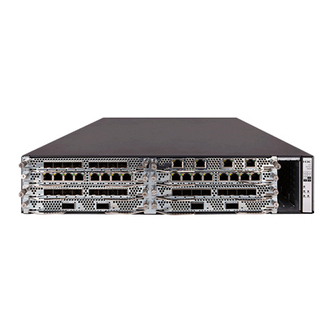
Appendix A Chassis and FRU views and technical specifications Chassis and FRU views F5030/F5060/F5080/F5000-M/F5030-6GW/F5000-A front view On the front panel, the F5030/F5060/F5080/F5000-M/F5030-6GW/F5000-A firewall provides eight interface module slots and two hard disk slots. Figure 27 Front view of the F5030/F5060/F5080/F5000-M/F5030-6GW/F5000-A (1) Interface module slots (slots 1 through 8) (2) Hard disk slot HD0 (3) Hard disk slot HD1... -
Page 46: Rear View
Rear view On the rear panel, the firewall provides four 10/100/1000Base-T auto-sensing copper Ethernet ports, four 1000Base-X fiber Ethernet ports, two USB ports, one console port, two fan tray slots, and two power module slots. The copper ports and fiber ports form four combo interfaces. The rear view is similar for all the firewalls except that the rear panels of the F5000-D, F5030, F5060, and F5080 do not have management port marks. -
Page 47: Interface Module Views
Interface module views Table 15 displays the slots available for interface module installation. Table 15 Interface module and device slot compatibility Interface F5030/F5060/F5080/F5 F5030-D/F5060-D/F50 F5000-M/F5000-A module 030-6GW 80-D NSQM1TG8A NSQM1QG2A Slots 1 through 3 Slots 1 through 3 Slots 2/1 through 2/3 NSQM1G4XS4 NSQM1GT8A NSQM1GP8A... - Page 48 Figure 33 NSQM1G4XS4 front view (1) LED (2) 1000Base-X fiber Ethernet ports (3) 10GBase-R fiber Ethernet ports (4) Captive screw (5) Ejector lever NSQM1GT8A The NSQM1GT8A interface module provides eight 10/100/1000BASE-T copper ports. Figure 34 NSQM1GT8A front view (1) LED (2) 10/100/1000BASE-T copper Ethernet ports (3) Captive screw (4) Ejector lever...
-
Page 49: Power Module Views
Figure 36 NSQM1GT4PFCA front view (1) LED (2) 10/100/1000BASE-T copper Ethernet ports (3) Captive screw (4) Ejector lever Power module views The firewall comes with power module slot PWR0 installed with a filler panel and power module slot PWR1 empty. You can install two power modules to achieve 1+1 power redundancy or install only one power module. -
Page 50: Technical Specifications
DC power module Figure 38 DC power module front view (1) Retaining latch (2) Handle (3) Power receptacle Technical specifications Dimensions and weights Table 16 Dimensions and weights Model Dimensions (H × W × D) Weight 88.1 × 440 × 660 mm (3.47 × 17.32 × 25.98 in) Chassis 20.1 kg (44.31 lb) (excluding rubber feet and mounting brackets) -
Page 51: Power Consumption
Item Specification • F5030/F5030-D/F5000-M/F5030-6GW/F5000-A: 16 GB DDR3 SDRAM Memory • F5060/F5060-D: 32 GB DDR3 SDRAM • F5080/F5080-D: 64 GB DDR3 SDRAM Power consumption Table 18 Power consumption Item Specification Firewall F5030/F5060/F5080/F5000-M 191 W F5030-D/F5060-D/F5080-D 250 W NSQM1MPULA 7.5 W Interface module NSQM1TG8A 12.96 W NSQM1QG2A... -
Page 52: Port Specifications
Connection to the serial port of a local PC to run the terminal Services emulation program • NOTE: For more information about transceiver modules, see H3C Transceiver Modules User Guide. USB port Table 23 USB port specifications Item Specification Mode... - Page 53 GE copper port Table 24 GE copper port specifications Item Specification Connector RJ-45 Standard compliance 802.3, 802.3u, and 802.3ab Interface type MDI/MDI-X autosensing Cable type Category 5 or higher twisted pair cable Transmission distance 100 m (328.08 ft) 10 Mbps, half/full-duplex Interface speed and duplex mode 100 Mbps, half/full-duplex 1000 Mbps, full-duplex...
- Page 54 Central Fiber diameter Mode bandwidth Transceiver module wavelength Fiber mode (µm) (MHz*km) (nm) SFP-GE-LH40-SM1550 1550 9/125 SFP-GE-LH80-SM1550 1550 9/125 SFP-GE-LH100-SM1550 1550 9/125 Table 27 1000Base-X SFP transceiver module specifications (2) Transmission Transmitted optical Received optical Transceiver module distance power (dBm) power (dBm) 550 m (1804.46 ft) 500 m (1640.42 ft)
- Page 55 Table 29 SFP+ transceiver module specifications (1) Central Fiber Fiber diameter Mode bandwidth Transceiver module wavelength mode (µm) (MHz*km) (nm) 2000 50/125 SFP-XG-SX-MM850-A 62.5/125 1500 50/125 SFP-XG-LX220-MM1310 1310 62.5/125 SFP-XG-LX-SM1310 1310 9/125 SFP-XG-LH40-SM1550 1550 9/125 Table 30 SFP+ transceiver module specifications (2) Transmitted Received Transmission...
- Page 56 40 GE fiber port Table 31 40 GE fiber port specifications Item Specification Connector type Transceiver module type QSFP+ Standard compliance 40GBASE-R Interface speed LAN PHY: 40 Gbps Table 32 QSFP+ transceiver module specifications (1) Central Fiber Mode Transceiver module Fiber mode wavelength diameter...
-
Page 57: Appendix B Leds
Appendix B LEDs Front panel and rear panel LEDs Table 34 Front panel and rear panel LED description Mark Status Description Flashing green (1 Hz) The firewall is operating correctly. The system is starting or loading Flashing green (8 Hz) System status LED software. -
Page 58: Interface Module Leds
Mark Status Description The system is not powered on or has failed. Steady green The MPU is the active MPU. ACT LED The MPU is the standby MPU. The port is receiving or sending Flashing yellow data at a low speed. Steady yellow A low-speed link is present. -
Page 59: Appendix C Cables
Appendix C Cables Console cable A console cable is an 8-core shielded cable with a crimped RJ-45 connector at one end and a DB-9 female connector at the other end. The RJ-45 connector is for connecting to the console port of the firewall, and the DB-9 female connector is for connecting to the serial port on the configuration terminal. - Page 60 Table 38 Description for commonly used Ethernet twisted pair cables Type Description Category 5 Suitable for data transmission at a maximum speed of 100 Mbps Category 5e Suitable for data transmission at a maximum speed of 1000 Mbps Category 6 Suitable for data transmission at a speed higher than 1 Gbps Based on whether a metal shielding is used, Ethernet twisted pair cables can be classified into shielded twisted pair (STP) and unshielded twisted pair (UTP).
- Page 61 Figure 41 Straight-through cable Figure 42 Crossover cable Select an Ethernet twisted pair cable according to the RJ-45 Ethernet port type on your device. An RJ-45 Ethernet port can be MDI (for routers and PCs) or MDIX (for switches). Table 39 Table 40 show their pinouts.
-
Page 62: Making An Ethernet Twisted Pair Cable
10Base-T/100Base-TX 1000Base-T Signal Function Signal Function Sends data BIDA- Bi-directional data cable A- Receives data BIDB+ Bi-directional data cable B+ Reserved BIDC+ Bi-directional data cable C+ Reserved BIDC- Bi-directional data cable C- Receives data BIDB- Bi-directional data cable B- Reserved BIDD+ Bi-directional data cable D+ Reserved... -
Page 63: Optical Fiber
Cut the top of the wires even with one another and insert the wires into the RJ-45 connector. Make sure the wires extend to the front of the RJ-45 connector and make good contact with the metal contacts in the RJ-45 connector and in the correct order. Crimp the RJ-45 connector with the crimping tool until you hear a click. - Page 64 • Before connecting an optical fiber, use dust free paper and absolute alcohol to clean the end face of the two fiber connectors. You can brush the end faces only in one direction. • Never bend or curve a fiber. •...
Need help?
Do you have a question about the SecPath F5030 and is the answer not in the manual?
Questions and answers