Table of Contents
Advertisement
Quick Links
Libretto istruzioni
Instruction booklet
Notice de pose et d'entretien
Gebrauchsanleitung
Manual de instrucciones
COD. 5.371.084.820
VORTICE LIMITED
Beeches House - Eastern Avenue
Burton on Trent
DE13 0BB
Tel. (+44) 1283-492949
Fax (+44) 1283-544121
UNITED KINGDOM
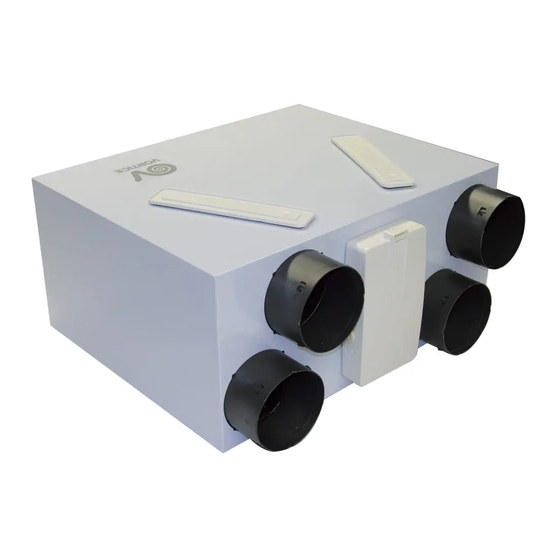
VORT HR 200
VORTICE FRANCE
72 Rue Baratte-Cholet
94106 Saint Maur Cedex
Tel. (+33) 1-55.12.50.00
Fax (+33) 1-55.12.50.01
FRANCE
28/02/2011
VORTICE ELETTROSOCIALI S.p.A.
Strada Cerca, 2 - frazione di Zoate
20067 TRIBIANO (MI)
Tel. (+39) 02-90.69.91
Fax (+39) 02-90.64.625
ITALIA
Advertisement
Table of Contents

Subscribe to Our Youtube Channel
Related Manuals for Vortice VORT HR 200


Summary of Contents for Vortice VORT HR 200
- Page 1 Libretto istruzioni Instruction booklet Notice de pose et d’entretien Gebrauchsanleitung Manual de instrucciones VORT HR 200 COD. 5.371.084.820 28/02/2011 VORTICE LIMITED VORTICE FRANCE VORTICE ELETTROSOCIALI S.p.A. Beeches House - Eastern Avenue 72 Rue Baratte-Cholet Strada Cerca, 2 - frazione di Zoate...
-
Page 2: Table Of Contents
Guarantee and responsibility......20 these instructions carefully. Vortice will not accept Warning ........21 any responsibility for damage to property or Caution . -
Page 3: Compliance With Building Codes
• damage caused by repairs or attempted repairs or by Continuous mechanical extract with heat recovery third parties not authorised by Vortice. (MVHR) is complied with by the new VORT HR 200 ultra- high ef ciency whole house heat recovery ventilation Responsibility system. -
Page 4: Warning
ENGLISH • Should the appliance be dropped or suffer a heavy Warning: blow, have it checked immediately by a Vortice Service This symbol indicates precautions that must Centre. be taken to avoid personal injury • The appliance must be installed by a professionally qualified electrician. -
Page 5: Items Supplied
ENGLISH Items supplied The main appliance components are as follows: • an outer casing and front cover in painted sheet metal; the casing houses the intake/outlet hose connections and the electrical connection box; the casing also houses the internal components and heat exchanger in an air tight housing;... - Page 6 ENGLISH Assembly The appliance comes with 2 rawlplugs with hooks for wall-mounting. Establish exactly where the appliance is to be positioned, bearing mind installation requirements. Vertical mounting Fix the hooks to the wall as shown in the diagrams that follow ( gs. 4,5,6,7,8).
- Page 7 ENGLISH Floor mounting (optional kit) Fresh air inlet The appliance can be horizontally oor mounted using ( g. 11) the special optional kit. Pipework connections ( g. 9). EXTRACT SUPPLY EXTRACT SUPPLY FROM FROM EXTERNAL EXTERNAL INTERNAL INTERNAL This inlet is used for carrying fresh air from the exterior; the duct must be thermally insulated and have devices tted to absorb vibration.
- Page 8 ENGLISH Air outlet ( g. 13) This outlet delivers fresh air into the house once it has been treated in the heat exchanger. Connecting the condensation drainage hose. The connection point for this hose is located on the underside of the appliance; it is to be connected following description below...
- Page 9 ENGLISH Condensation is drained away by connecting the hose provided to the condensation drainage coupling. To prevent formation of air locks a U-bend must be created with the hose as shown in g. 21.
-
Page 10: Electrical Connections
ENGLISH Electrical connections Wiring diagram with switch ( g. 24) Power supply wiring: you will need a cable with 5 X 1.5mm cores [4 plus earth] ( g. 22) Wiring diagram with timer ( g. 25) Connecting the power supply (N1, L1 and earth) and ma- ximum speed terminals ( g. -
Page 11: Function
ENGLISH Function Setting fan speed Using the switch to set fan speed ( g. 26). Motors The appliance usually operates at minimum speed The appliance is equipped with: (V min ); the user can switch to the maximum speed • two brushless motors speci cally designed to (V max ) with the switch. -
Page 12: Maintenance/Cleaning
ENGLISH Maintenance/Cleaning Filters The user is responsible for the periodical maintenance of lters. The lters have to be periodically cleaned to ensure that the appliance continues operating ef ciently. They should be replaced at least once a year. To access the lters, follow the instructions below: •... - Page 13 ENGLISH If the appliance remains out of use for extended periods, we advise removing the lters to prevent any possible damage from the build-up of condensation. Heat exchanger Heat exchangers do not usually need frequent cleaning. Any need for cleaning can be determined by a high degree of air pollution (both entering and leaving the house) and by the lters being in poor condition.
- Page 14 ENGLISH Cleaning the outside To clean the outside of the appliance, follow the instructions below: • disconnect the appliance from the mains; • only use a soft slightly damp cloth (fig. 40); • do not use abrasive and/or corrosive products (fig. 41); •...
-
Page 15: Initial Settings
ENGLISH Initial settings 1) Before connecting the appliance to the mains, connect the external radio module to the electronic (for installer only) circuit board and con gure the dip-switch as shown There are two ways for the installer to make the initial ap- ( gure 43). - Page 16 ENGLISH ON/OFF key ( g. 44) V min setting ( g. 46): 14:38 SL03 SUMMER DISPLAY TIMER MODE • to display the setting, press SET, NEXT (starting from NEXT ENTER the main menu); • to set the value of the ashing eld with the + and - keys (from 0 to 60);...
- Page 17 ENGLISH Manually making settings using the dip-switch The pre-selected con guration has to match the type of 1) Before connecting the appliance to the mains, installation (number of rooms served, length of con gure the dip-switch using the following method: pipework, etc.) to be carried out.
-
Page 18: Important Information Regarding Eco-Compatible Disposal
ENGLISH Activating the timer. Important information on eco-compatible In timer mode, the appliance will operate for 30 minutes disposal at V max and then return automatically to V min ; to permit new settings, connect the appliance to a keypad (not to IN CERTAIN EUROPEAN UNION COUNTRIES, THIS a switch). -
Page 19: Building Regulations Document F1 2006
1 2 . G u i d e p r a t i c h e . q x d 1 8 - 1 2 - 2 0 0 7 9 : 1 0 P a g i n a 5 9 BUILDING REGULATIONS DOCUMENT F1 2006 BUILDING REGULATIONS DOCUMENT F1 2006 SYSTEM 4...
Need help?
Do you have a question about the VORT HR 200 and is the answer not in the manual?
Questions and answers