Table of Contents
Advertisement
Available languages
Available languages
Quick Links
Advertisement
Table of Contents

Summary of Contents for ROBBE LIMIT PRO
- Page 1 PNP-Version Nr.: 2641 ARF-Version Nr.: 2642 www.robbe.com...
- Page 2 • Durch Absturz beschädigte oder nass gewordene Geräte, selbst wenn sie wieder trocken sind, nicht mehr verwenden! Entweder von Ihrem Fachhändler oder im Robbe Service überprüfen lassen oder ersetzen. Wenn Sie Ihr Modell mit einem Video bzw. Bild aufnahmefähigen Gerät (z.B. FPV Kameras, Actionscams etc.) Durch Nässe oder Absturz können versteckte Fehler entstehen, welche nach kurzer Betriebszeit zu einem...
- Page 3 • Legen Sie Ihrer Sendung den Kaufbeleg (Kassenzettel) bei. • Die Geräte wurden gemäß der Bedienungsanleitung betrieben. Copyright 2018 • Es wurden ausschließlich empfohlene Stromquellen und original robbe Zubehör verwendet. Modellbau Lindinger 2018 • Feuchtigkeitsschäden, Fremdeingriffe, Verpolung, Überlastungen und mechanische Beschädigungen Kopie und Nachdruck, auch auszugsweise, nur mit schriftlicher Genehmigung.
- Page 4 T E C H N I S C H E D A T E N Wir beglückwünschen Sie zum Erwerb des LIMIT PRO! Es handelt sich um einen sehr dynamisch zu fliegen- den Voll-GfK Hotliner von hoher Qualität, der in einem breiten Geschwindigkeitsbereich eingesetzt werden kann.
- Page 5 Bau- und Betriebsanleitung H Ö H E N L E I T W E R K Markieren Sie die Mitte des Höhenruders auf der Schleifen Sie das Höhenruderhorn beidseitig an Unterseite. und kleben es mit angedicktem 24h Epoxyharz Fräsen Sie einen kleinen Schlitz 2mm außermittig oder Uhu Endfest 300 ein.
- Page 6 Bau- und Betriebsanleitung R U M P F Durch das in Neutralposition fixierte Höhenruder und das Servohorn in 90° Stellung, ergibt sich Hängen Sie das Höhenruderhorn in das Gestänge nun automatisch die endgültige Position des Servos. Die Servodrehachse sollte 90° zum Gestänge ein und montieren das Höhenruder mit den M3 stehen.
- Page 7 Bau- und Betriebsanleitung T R A G F L Ä C H E Rauhen Sie die Oberfläche in den Querruder- Entfernen Sie die Laschen vom Servogehäuse. schächten mit Schmirgelpapier an. Danach wird es komplett eingeschrumpft und der Schrumpfschlauch grob angeschliffen. Stecken Sie ein Verlängerungskabel auf und führen es durch die Öffnung in der Tragflächenmitte.
- Page 8 Bau- und Betriebsanleitung M O N T A G E U N D J U S T A G E Montieren Sie die Fläche auf dem Rumpf. Achten Schalten Sie den Sender mit entsprechend voreingestelltem Modellspeicher ein und klemmen Sie den Akku an.
- Page 9 E R S A T Z T E I L E Ersatzteil Artikelnummer Rumpf (ohne Elektronik) 264101 Tragfläche (ohne Servos) 264102 Höhenruder 264103 Schutztasche Limit Pro 264104 Servo FS 155 BB MG 9106 Motor X36-800 5800 Aeronaut Klappluftschraube 12x8“ 7234/50 Turbo Spinner 38mm mit Kühlluftöffnung 20736 F Ü...
- Page 10 The best position of the antenna is to the side of the model. checked by your specialist dealer or in the Robbe Service or have it replaced. Hidden faults can occur due to wetness or a crash, which lead to a functional failure after a short operating time.
- Page 11 The original declaration of conformity can be found on the Internet at www.robbe. Therefore, we accept no liability for losses, damage or costs arising from or in any way connected with incorrect use and operation.To the extent permitted by law, the obligation to pay damages, irrespective of...
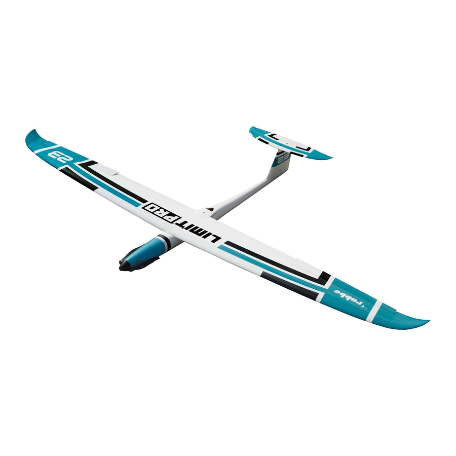
- Page 12 Congratulations on your purchase of the new LIMIT PRO! The LIMIT PRO is a high-quality FRP hotliner with a dynamic flight envelope. It can be flown within in a broad speed range. There are various ways of constructing the model, depending on your preferences.
- Page 13 Instructions and User Manual E L E V A T O R Mark the center of the elevator on the bottom. Grind the elevator horn on both sides and glue it with thickened 24h epoxy resin or Uhu Endfest 300. Milling a small slot 2mm eccentrically to accommo- The bore points backwards, so you got a distance date the rudder horn of about 10x1.8mm, starting...
- Page 14 Instructions and User Manual F U S E L A G E Due to the fixed in neutral position elevator and the servo horn in 90 ° position, the final position Hook the elevator horn into the linkage and mount of the servo is now automatically obtained.
- Page 15 Instructions and User Manual W I N G Sand the surface in the aileron servo housings with Remove the tabs from the servo housing. Then it sand paper. is completely shrunk and the shrink tube roughly grinded. Plug in an extension cable and guide it through the opening in the center of the wing.
- Page 16 Instructions and User Manual I N S T A L L A T I O N A N D T U N I N G P R O C E S S Mount the wing on the fuselage. Make sure that no Turn on the transmitter using the preset model memory and connect the battery.
- Page 17 S P A R E P A R T S Spare Part Item Number Fuselage (w/o electronics) 264101 Wing Set (without Servos) 264102 Elevator 264103 Protection Bag Limit Pro 264104 Servo FS 155 BB MG 9106 Motor X36-800 5800 Aeronaut Folding Prop 12x8“ 7234/50 Turbo Spinner 38mm...
- Page 18 Instructions and User Manual F O R Y O U R N O T E S...
- Page 19 Instructions and User Manual F O R Y O U R N O T E S...
- Page 20 rev.6/2018 SM+M...


Need help?
Do you have a question about the LIMIT PRO and is the answer not in the manual?
Questions and answers