Table of Contents
Advertisement
Quick Links
Download this manual
See also:
Manual
Advertisement
Table of Contents

Subscribe to Our Youtube Channel
Related Manuals for KanexPro MX-HDBT8X818G


Summary of Contents for KanexPro MX-HDBT8X818G
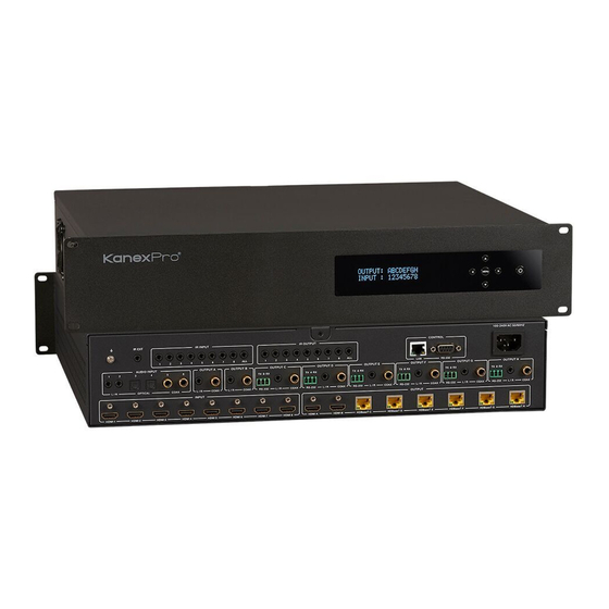
- Page 1 MX-HDBT8X818G 8 by 8 HDMI and HDBaseT Matrix Switcher with Audio Matrixing All Rights Reserved MPN# MX-HDBT8X818G...
-
Page 2: Table Of Contents
Thank you for purchasing this product For optimum performance and safety, please read these instructions carefully before connecting, operating or adjusting this product. Please keep this manual for future reference. Surge protection device recommended This product contains sensitive electrical components that may be damaged by electrical spikes, surges, electric shock, lighting strikes, etc. -
Page 3: Introduction
1. Introduction The 8 by 8 HDMI and HDBaseT Matrix Switcher supports transmission of video (resolution up to 4K2K@60Hz YUV 4:4:4, 18Gbps, HDCP 2.2) and audio (multi- channel digital / analog stereo) while providing flexible control via front panel button (with OLED screen), IR remote, RS-232 or Web GUI. -
Page 4: Package Contents
outputs ☆ Video resolution up to 4K@60Hz (YUV 4:4:4) for all HDMI ports ☆ All HDMI outputs support audio embed and de-embed ☆ All HDBaseT ports support 4k@60Hz (YUV 4:4:4) and distance up to 295 feet / 90 meters or 1080p@60Hz and distance up to 330 feet / 100 meters via CAT 6/6a/7 cable ☆... -
Page 5: Specifications
⑥ 1x 100~240V AC 50/60Hz Power cable ⑦ 1x RS-232 serial cable (1.5m, male to femle head) ⑧ 16x 3-pin Phoenix Connectors ⑨ 12x Mounting Ears ⑩ 1x User Manual 4. Specifications Technical HDMI Compliance HDMI 2.0b HDCP Compliance HDCP 2.2 and HDCP 1.4 Video Bandwidth 18Gbps Video Resolution... -
Page 6: Operation Controls And Functions
Output Ports 2×HDMI Type A [19-pin female] 9×IR OUTPUT [3.5mm Stereo Mini-jack] 8×L/R Audio OUTPUT [3.5mm Stereo Mini- jack] 8×Coaxial Audio OUTPUT [RCA] 6×HDBaseT OUTPUT [RJ45] Control Ports 6×RS-232 [Phoenix jack] 1×LAN [RJ45] 1×RS-232 [DB9] HDBaseT Receiver Input Ports 1×HDMI Type A [19-pin female] 1×IR OUT [3.5mm Stereo Mini-jack] Control Ports 1×RS-232 [Phoenix jack]... - Page 7 OLED screen Display system status including input / output port, EDID select, PIP Set and View IP etc. IR Window IR receiver window, it receives IR remote control signal to control this device. Left / Right / When the product is powered on, the OLED screen will Up / Down / display input and output status before power off about MENU buttons...
-
Page 8: Rear Panel
“Down” button to select storage location. Then press the “Right” button again to confirm this operation. ④ Recall Preset: Press the “Right” button to recall previous preset configuration, press “Up” or “Down” button to select storage location. Then press the “Right” button again to confirm this operation. - Page 9 Number Name Function descriptions The housing is connected to the ground. IR EXT If the front IR window of the unit is obstructed or the unit is installed in a closed area out of infrared line of sight, the IR receiver cable can be inserted to the “IR EXT” portto receiving the IR remote signal.
- Page 10 Connection ▪ Illuminate: Transmitter and Receiver are in good Signal connection status. Indicator ▪ Flashing: Transmitter and Receiver are in poor Lamp connection status. ▪ Dark: Transmitter and Receiver are not connected. Data Signal ▪ Illuminate: HDMI signal with HDCP. Indicator ▪...
-
Page 11: Ir Remote
: Select the last or next input source button. ③ Output A/B/C/D/E/F/G/H: Select output source button. All: Select all output source simultaneously. For example, when you select the “All” button and then select input “1” button, at this time the input “1” source will output to all output device. -
Page 12: Ir Control System
The second way: If the front IR window of the Matrix is obstructed or the Matrix is installed in a closed area out of infrared line of sight, the IR receiver cable can be inserted to the “IR EXT” port to receiving the IR remote signal. The distance of the IR remote is the further 7 meters and the IR remote is directly faced to the IR receiver head. - Page 13 diagram is shown as below. 1. At Matrix End: The 3.5mm jack IR blaster cable is inset the IR OUTPUT port and the 3.5mm jack IR receiver cable is inset the IR INPUT port at the rear of the Matrix. If you want to control the HDMI input source device such as DVD, the IR blaster head is putted the DVD aside.
- Page 14 display device such as TV, the IR blaster cable is putted the TV aside. IR receiver head receives the remote control signal about the Matrix’s input source device. 3. Control method: You must pay attention to an important thing, the IR signal transmission follow the video signal between Matrix and HDBaseT.
-
Page 15: Ir Cable Pin Assignment
8. IR Cable Pin Assignment 9. HDBaseT Receiver... - Page 16 Number Name Function descriptions POWER LED Power LED indicator. ARC LED ARC LED status indicator. ARC button Turn on/off the ARC function. DC 24V Plug the 24V/1A adapter to AC wall outlet for power supply. HDBaseT IN HDBaseT input port, connect to “HDBaseT OUT” port Matrix with an CAT able.
-
Page 17: Edid Management
RS-232 Connect to a PC or control system by 3-pin phoenix connector cable to transmission command between Matrix and HDBaseT receiver. SERVICE SEL Service port, reserved port for manufacturer use. 10. EDID Management This Matrix has 19 factory defined EDID settings and 8 copy EDID mode. You can select defined EDID mode or copy EDID mode to input port through on-panel button or Web GUI. - Page 18 Web GUI Operation: Please check “EDID page” in the “12. Web GUI User Guide”. There are predefined EDID setting that you can select: EDID Mode EDID Description 720p, Stereo Audio 2.0 1080p, Stereo Audio 2.0 1080p, Dolby/DTS 5.1 1080p, HD Audio 7.1 1080i, Stereo Audio 2.0 1080i, Dolby/DTS 5.1 1080i, HD Audio 7.1...
-
Page 19: Audio Matrix
4K2K60_420, Dolby/DTS 5.1 4K2K60_420, HD Audio 7.1 4K2K60_444, Stereo Audio 2.0 4K2K60_444, Dolby/DTS 5.1 4K2K60_444, HD Audio 7.1 Copy HDMI OUT A Copy HDMI OUT B Copy HDBaseT OUT C Copy HDBaseT OUT D Copy HDBaseT OUT E Copy HDBaseT OUT F Copy HDBaseT OUT G Copy HDBaseT OUT H 11. - Page 20 In RS-232 port about matrix and receiver, this is a channel about transmission command between matrix and receiver. You can connect PC or another device such as HDMI Matrix in RS-232 port, and you can control the HDMI Matrix through the remote PC.
-
Page 21: Web Gui User Guide
12. Web GUI User Guide The Matrix can be controlled via Web GUI. You must know current Matrix IP address. The default IP address is 192.168.1.100. You can get the current IP address through on-panel. The LAN port of the Matrix connects directly a PC with an UTP cable. The “Figure 4”... - Page 22 “Right” button to check current IP address and DHCP status. In this moment, you can get current IP address. Step 1: The LAN port connects directly PC with an UTP cable. Step 2: On the PC, go to Control Panel > Network and Internet > Network Connections >...
- Page 23 Choose “Use the following IP address”, input 192.168.1.200 as IP address, 255.255. 255.0 as Subnet mask, and then click on OK, click on OK again. Notice: The IP address of the computer and Matrix should be in the same network segment.
- Page 24 192.168.1.X (X contains 1~255 except 100). Step 3: Input the IP address from front panel into your brower on the PC to enter Web GUI page, These pages are show as below. General page ① Clicking the “Status” button will display current the Matrix input and output port status.
- Page 25 voice. Close this switch, it will mute. ④ There will be a option frame when you click this button. Clicking the “Yes” button will reboot the product, after reboot the product and all functions will go back to the previous function status. Clicking the “No” button will close the option frame.
- Page 26 OUTPUT A: There will be a option frame when you click the green area about OUTPUT A port. Please see above “Picture 1”. You can select an input source to OUTPUT A output. Audio: There will be a drop-down frame when you click the blue arrow area. Please see above “Picture 2”.
- Page 27 Note: The other output ports have similar to function about the OUTPUT A. Audio Matrix page OUTPUT A: There will be a drop-down frame when you click the blue arrow area. Please see “Picture 1”. You can select an audio source to OUTPUT A audio output.
- Page 28 Note: The others OUTPUT ports have similar function about OUTPUT A. EDID page Set EDID Mode: You will see the EDID mode list and input port frame when you click the blue arrow area. Please see Picture 1 and Picture 2. You need to select an EDID mode to an input source.
- Page 29 source EDID status currently. Network page Network Configuration ◆ In DHCP open status: DHCP switch: Obtain automatically the network configuration information, including IP address, Subnet, Gate. ◆ In DHCP close status: DHCP switch: If the DHCP switch has been closed, you can set IP, Subnet, Gate address.
- Page 30 have changed the IP address, and you can continue use Web GUI function. But next time you connect Web GUI, you need to check current the IP address on the front panel. The IP address will recover default 192.168.1.100 when the product is set factory reset.
-
Page 31: Ascii Control Command
Upgrade: Select bin. upgrade file, then click the “Upgrade” button to upgrade. At this time, you will see a upgrade progress. The upgrade has finished when the upgrade progress up to 100%. Notice: This Upgrade port can only upgrade MCU. 13. - Page 32 Double click the “Docklight” shortcut icon. Please see the following picture 1. You will see the following page.
- Page 33 Click the “COM” area, there will be a “Project Settings” page. Choose the COM portto connect the software, and you need to setting the Baud Rate, Data Bits, Parity,Stop Bits and then click the “OK” button. Please see the following page.
- Page 34 Double click the “label 1” blank area. You will see the following page. At “label 2”, you can explain sequence definition. At “label 3”, you need to choose the sequence mode. At “label 4”, you can input the RS-232 command of the product. Then click the “OK”button.
- Page 35 The ASCII list about the product is shown as below.
-
Page 37: Application Example
14. Application Example... -
Page 38: Faq
15. FAQ... - Page 39 1. Q: Does this product require an HDMI and CAT line length for the connection interface? A: According to line length test. When the resolution is 1080p@60Hz 12 bit, and the HDMI input / output line length up to 3m / 15m. When the resolution is 4K@24Hz, and the HDMI input / output line length up to 3m / 10m.
- Page 40 After Sales-Service If problems arise when operating the device, please refer to this user manual. Any transport costs are borne by the users during the warranty. 1. Product Limited Warranty: We warrant that products will be free from defects in materials and workmanship for three years, which starts from the first day the product exits warehouse.
- Page 41 • Product version and name. • Detailed failure situations. Remarks: For any questions or troubleshooting please contact your local distributor or email support@kanexpro.com or call 888-975-1368...
- Page 42 KanexPro has been advised of the possibility of such damages...
- Page 43 Brea California, www.kanexpro.com...
Need help?
Do you have a question about the MX-HDBT8X818G and is the answer not in the manual?
Questions and answers