
Subscribe to Our Youtube Channel
Related Manuals for KanexPro MX-HDBASE6X6-4K


Summary of Contents for KanexPro MX-HDBASE6X6-4K
- Page 1 MX-HDBASE6X6-4K 4K HDBaseT 6X6 Matrix Switcher Drive the Distance with 4K Ultra HD to 6 outputs, De-embed audio, IR & RS-232 All Rights Reserved Version: MX-HDBASE6X6-4K_2016V1.1...
- Page 2 All product function is valid till 2017-9-2. KanexPro Trademarks KanexPro Product model and Logo are trademarks. Any other trademarks mentioned in this manual are acknowledged as the properties of the trademark owner. No part of this publication may be copied or reproduced without prior written consent.
- Page 3 KANEXPRO MX-HDBASE6X6-4k SAFETY PRECAUTIONS To insure the best from the product, please read all instructions carefully before using the device. Save this manual for further reference. Unpack the equipment carefully and save the original box and packing material for possible future shipment ...
-
Page 4: Table Of Contents
KANEXPRO MX-HDBASE6X6-4k Contents 1. Introduction ......................... 1 1.1 Introduction to the MX-HDBASE6X6-4K ............1 1.2 Features ......................1 1.3 Package List ...................... 2 2. Product Description ....................3 2.1 Front Panel ......................3 2.2 Rear Panel ......................4 3. System Connection ..................... 5 3.1 System Applications .................. - Page 5 KANEXPRO MX-HDBASE6X6-4k 4.3.5 Basic Settings ..................17 4.3.6 RS232 Communication Commands ............18 4.4 TCP/IP Control....................25 4.4.1 Control Modes ..................25 4.4.2 GUI for TCP/IP control ................27 4.4.3 GUI Update.................... 30 4.5 Firmware Update via USB ................30 5.
-
Page 6: Introduction
1. Introduction 1.1 Introduction to the MX-HDBASE6X6-4K The KanexPro MX-HDBASE6X6-4K matrix switcher is a professional 6 HDMI input to 6 HDBaseT output switch with 3 HDMI mirrored outputs designed for routing 4K/60 Hz applications supporting HDCP 2.2. For proficient audio capabilities, it includes 6 stereo audios and 6 digital coax outputs for de-embedding to analog audio and HDMI digital audio respectively. -
Page 7: Package List
19" (1U) rack-mountable steel enclosure External International power supply (100V-240V AC,50/60Hz) 1.3 Package List 1 x MX-HDBASE6X6-4K 2 x Mounting ears (6 x Screws) 1 x RS232 cable 1 x IR Receiver 4 x Plastic cushions (4 x Black Screws) ... -
Page 8: Product Description
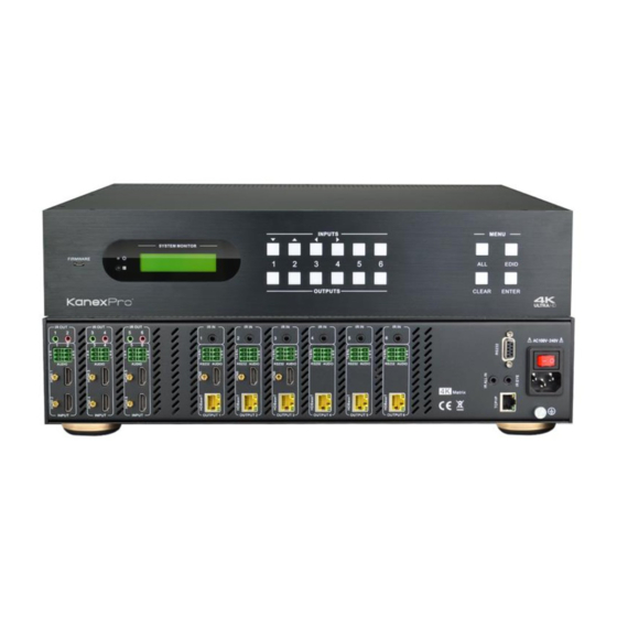
KANEXPRO MX-HDBASE6X6-4k 2. Product Description 2.1 Front Panel INPUTS MENU SYSTEM MONITOR FIRMWARE EDID CLEAR ENTER OUTPUTS Name Description Firmware Micro USB port for updating firmware ① Power Illuminate red when power on. ② Indicator In-built IR sensor, receive IR signals sent from IR remote. -
Page 9: Rear Panel
KANEXPRO MX-HDBASE6X6-4k 2.2 Rear Panel IR OUT IR OUT IR OUT IR IN IR IN IR IN IR IN IR IN IR IN RS232 AUDIO RS232 AUDIO RS232 AUDIO RS232 AUDIO RS232 AUDIO RS232 AUDIO Matrix HDCP2.2 INPUT INPUT INPUT... -
Page 10: System Connection
3. System Connection 3.1 System Applications As its good performance in control and transmission, the MX-HDBASE6X6-4K can be widely used in computer realm, monitoring, large screen displaying, conference system, television education and bank securities institutions etc. -
Page 11: Connection Diagram
MX-HDBASE6X6-4k 3.3 Connection Diagram 3.4 Connection Procedure 1) Connect HDMI sources (e.g. DVD) to HDMI inputs of the MX-HDBASE6X6-4K with HDMI cables. 2) Connect auxiliary audio sources to the AUDIO IN ports with audio cables. 3) Connect HDBaseT receivers (e.g. TPHD402PR) to the HDBaseT Output ports with twisted pair. -
Page 12: Connection With Hdbase70Poer
MX-HDBASE6X6-4k directionally between MX-HDBASE6X6-4K and far-end receivers. 7) MX-HDBASE6X6-4K can collect IR signal sent by the included IR remote via its built-in IR sensor or through external IR receiver connected to the IR IN/ IR EYE/ IR ALL IN port. The IR signal can be transmitted bi-directionally between MX- HDBASE6X6-4K and far-end receivers. -
Page 13: System Operations
KANEXPRO MX-HDBASE6X6-4k 4. System Operations 4.1 Front Panel Button Control MX-HDBASE6X6-4K provides with convenient front panel button control. Here we make a brief introduction to the system operations. 4.1.1 Switching I/O connection To convert one input to an output: Operation: “input”+“output”+“ENTER”... -
Page 14: Edid Management
If the conversion failed, they will be off immediately. 4.1.2 EDID Management MX-HDBASE6X6-4K features EDID management to maintain compatibility between all devices. It can be controlled via EDID learning and EDID invoking. EDID Learning (from output): ... -
Page 15: Inquiry
KANEXPRO MX-HDBASE6X6-4k Press and hold “EDID” for 3 seconds to enter EDID invoking mode, in this mode, use output buttons 1/2 to switch among the 5 embedded EDID data. Then press “ENTER” to confirm invoking. Format: Press and hold “EDID” for 3 seconds, “INPUTS” +“OUTPUTS 1/2”+“ENTER”. -
Page 16: Clear Operation
“ENTER” to carry it on. When you press it, the matrix will return to the previous status. 4.2 IR Control By using IR & HDBaseT transmission technology, the MX-HDBASE6X6-4K has some functions as follows: 1) Control far-end output device from local. -
Page 17: Usage Of Ir Remote
In EDID invoking mode: press button 1/2 to switch among the 5 embedded EDID data Note: With this IR remote, MX-HDBASE6X6-4K can be controlled by the built-in IR, the extended IR receiver connected to the “IR EYE”/”IR ALL IN” and the IR receiver on the far-end receiver. - Page 18 KANEXPRO MX-HDBASE6X6-4k Connect an IR receiver with IR carrier to the IR IN port of MX-HDBASE6X6-4K; users can control far-end output displayer via its IR remote from local. In that case, the IR signal is transferred via twisted pair. Only the corresponding IR OUT port can emit control signals to the remote display.
-
Page 19: Control Local Device Remotely
KANEXPRO MX-HDBASE6X6-4k Receiver connected to IR ALL IN is not with carrier. 4.2.4 Control Local Device Remotely Connect IR receiver(s) to IR IN on far-end HDBT receiver(s), and IR Emitter(s) to IR OUT port of the switcher, and use the IR Remote of local source to control the device remotely. -
Page 20: Rs232 Control
4.3 RS232 Control 4.3.1 Connection with RS232 Communication Port Except the front control panel, the MX-HDBASE6X6-4K can be controlled by far-end control system through the RS232 communication port. This RS232 communication port is a female 9-pin D connector. The definition of its pins is listed in the table below. -
Page 21: Control Through 3-Pin Rs232 Port
KANEXPRO MX-HDBASE6X6-4k TPHD402PR 3rd party Control the switcher& 3rd-party Device through 9 pin female RS232 port Control the switcher: send RS232 commands directly Control 3 party: send command: “/+[Y]/[X]:******.” (Refer to for detailed information.) 4.3.3 Control through 3-pin RS232 port ... -
Page 22: Installation/Uninstallation Of Rs232 Control Software
Uninstallation Delete all the control software files in corresponding file path. 4.3.5 Basic Settings Firstly, connect MX-HDBASE6X6-4K with an input device and an output device. Then, connect it with a computer which is installed with RS232 control software. Double-click the software icon to run this software. -
Page 23: Rs232 Communication Commands
KANEXPRO MX-HDBASE6X6-4k The interface of the control software is showed as below: Parameter Configuration area Monitoring area, indicates Monitoring area, indicates whether the command whether the command sent works. sent works. Command Sending area Command Sending area Please set the parameters of COM number, baud rate, data bit, stop bit and the parity bit correctly, only then will you be able to send command in Command Sending Area. - Page 24 KANEXPRO MX-HDBASE6X6-4k Baud rate: 9600 Data bit: 8 Stop bit: 1 Parity bit: none Command Function Feedback Example System Commands /*Type; Inquire the models information. MUH66TPR2-N /%Lock; Lock the front panel buttons on the Matrix. System Locked! Unlock the front panel buttons on the /%Unlock;...
- Page 25 KANEXPRO MX-HDBASE6X6-4k Command Function Feedback Example Switch on the output channel [x]. X Open. (X=1~6) [x]@. Switch on all output channels. All Open. All@. Transfer the AV signal from the input channel [x1] to one or several output AV: X1-> X2 [x1]V[x2].
- Page 26 KANEXPRO MX-HDBASE6X6-4k Command Function Feedback Example Transfer the IR signal from output channel IR: X1-> X2 [x1]R[x2]. [x1] to input channel [x2]. (X1/ X2=1~6) Enable HDMI audio output of port x. DigitAudio ON with [x] DigitAudioON[ X=1, 2, 3, 4, 5, 6, enable this port.
- Page 27 KANEXPRO MX-HDBASE6X6-4k Command Function Feedback Example Set the audio part of input port [x] to PCM EDIDPCM[x]. EDIDPCM[x] format in EDID database. Hexadecimal EDID Get EDID data from output [x] and display EDIDG[x]. data carriage the output port number. return character Restore the factory default EDID data of EDIDMInit.
- Page 28 KANEXPRO MX-HDBASE6X6-4k Command Function Feedback Example Return the embedded EDID data ranked GetIntEDID[x]. x, [x]=1~6 GetInPortEDI Return the EDID data of input [x], [x]=1~6 D[X]. Auto HDCP management, activate carrier %0801. %0801 native mode Carrier native %0900. Switch to carrier native mode.
- Page 29 KANEXPRO MX-HDBASE6X6-4k Command Function Feedback Example Check the working mode of infrared Carrier native/ Force %9963. carrier. carrier IP:192.168.0.178 %9964. Check the IP address. (default) 1 2 3 4 Connect N Y Y Y %9971. Check the connection status of the inputs.
-
Page 30: Tcp/Ip Control
MX-HDBASE6X6-4K can be controlled by PC without Ethernet access or PC(s) within a LAN. Controlled by PC Connect a computer to the TCP/IP port of the MX-HDBASE6X6-4K, and set its network segment to the same as the MX-HDBASE6X6-4K’s. 25 |... - Page 31 Controlled by PC(s) in LAN Connect MX-HDBASE6X6-4K, a router and several PCs to setup a LAN (as shown in the following figure). Set the network segment of MX-HDBASE6X6-4K to the same as the router’s, then PCs within the LAN can control MX-HDBASE6X6-4K.
-
Page 32: Gui For Tcp/Ip Control
KANEXPRO MX-HDBASE6X6-4k Step3. Set the MX-HDBASE6X6-4K’s network segment to the same as the router. Step4. Set the PC’s network segment to the original ones. Step5. Connect the MX-HDBASE6X6-4K and PC(s) to the router. PC(s) within the LAN can control the MX-HDBASE6X6-4K asynchronously. - Page 33 KANEXPRO MX-HDBASE6X6-4k The button matrix displays every possible connection between every input and output, users can carry on the connections by clicking corresponding button. Buttons 1~9 at the right-bottom corner provides quick saving and recall for overall connection status. Users: Display or modify credential settings, front panel lock, and GUI version.
- Page 34 KANEXPRO MX-HDBASE6X6-4k Configuration: Set HDCP Compliance status for every input, and manage EDID. See the screenshot below: Network: Inquire and configure network settings including MAC address, IP address, subnet mask, and Gateway 29 | P a g e...
-
Page 35: Gui Update
Select the desired update file and press Apply, it will start upgrading then. 4.5 Firmware Update via USB MX-HDBASE6X6-4K boasts a USB port for online firmware upgrade on the front panel. Follow these steps to upgrade firmware: Step1. Copy the upgrade software and the latest upgrade file (.bin) to PC. - Page 36 KANEXPRO MX-HDBASE6X6-4k Note: To ensure available control, the COM number of the PC should be 1~9. 31 | P a g e...
-
Page 37: Specification
KANEXPRO MX-HDBASE6X6-4k 5. Specification Video Input Video Output 3 HDMI Input 6 HDMI Output 6 HDBaseT Female HDMI Input Output Female HDMI Female RJ45(with LED Connector Connector indicators) Input Level T.M.D.S. 2.9V~3.3V Output Level T.M.D.S. 2.9V~3.3V Output Differential) 100Ω (... -
Page 38: Panel Drawing
KANEXPRO MX-HDBASE6X6-4k 1 RS232 (9 pin female) 6 RS232s (3-pin pluggable terminal blocks) In-built IR sensor, RS232 IR Control 9 pin female Extended IR receiver Control TCP/IP Works with In-built web GUI Control General Power Power 105W (full load) 100V~240V AC... -
Page 39: Troubleshooting & Maintenance
KANEXPRO MX-HDBASE6X6-4k 6. Troubleshooting & Maintenance Problems Causes Solutions The connecting cables may Check whether the cables not be connected correctly connected correctly Color losing or no video or it may be broken. and in working condition. signal output Make sure the connection... - Page 40 KANEXPRO MX-HDBASE6X6-4k Power Indicator remains off Fail lose power Check whether the cables when powered on connection are connected correctly Change for another HDMI EDID management does The HDMI cable is broken cable which is in good not work normally at the output end.
-
Page 41: After-Sales Service
KANEXPRO MX-HDBASE6X6-4k 7. After-sales Service If you are encountering any issues when running the device, please check and treat the problems referred to this user manual. 1) Product Limited Warranty: We warrant that our products will be free from defects in materials and workmanship for three years, which starts from the first day the product leaves warehouse (check the SN mark on the product).
Need help?
Do you have a question about the MX-HDBASE6X6-4K and is the answer not in the manual?
Questions and answers