
Subscribe to Our Youtube Channel
Related Manuals for KanexPro HDMX44A-18G


Summary of Contents for KanexPro HDMX44A-18G
- Page 1 Ultra-Fast 4x4 HDMI Matrix Switcher with Audio Extraction 4K/60Hz All Right Reserved MPN: HDMX44A-18G VER 1.0...
- Page 2 SAFETY PRECAUTIONS Please read all instructions before attempting to unpack, install or operate this equipment and before connecting the power supply. Please keep the following in mind as you unpack and install this equipment: • Always follow basic safety precautions to reduce the risk of fire, •...
-
Page 3: Table Of Contents
INTRODUCTION 1. Introduction........................4 2. Applications.........................4 3. Package Contents.....................4 4. System Requirements.....................4 5. Features.........................4 6. Operation Controls and Functions..............5 6.1 Front Panel......................5 6.2 Rear Panel......................6 6.3 Remote Control.....................7 6.4 IR Cable Pinouts....................8 6.5 RS-232 Pinout and Defaults..............8 6.6 Front Panel LCD Menu................9 6.7 WebGUI Control...................14 6.7.1 Video Switch Tab................16 6.7.2 EDID Settings Tab................20... -
Page 4: Introduction
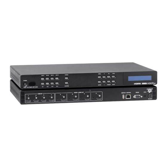
1. INTRODUCTION The KanexPro HDMX44A-18G is a4K UHD 4x4 HDMI Matrix that provides the ability to connect up to four 4K UHD HDMI sources to up to four 4K UHD HDMI displays and freely switch between them. This unit comes with full support for 18Gbps resolutions up to and including 4K@60Hz (4:4:4, 8-bit) as well as support for 16-bit Deep Color, HDR (High Dynamic Range), HD audio and other features defined by the HDMI 2.0 specification. -
Page 5: Operation Controls And Functions
• Supports six internal EDIDs, four external EDIDs copied from connected devices, and four user provided EDIDs • OSD with user customizable information text • Controllable via front-panel buttons with LCD, WebGUI, Telnet, RS-232, and IR remote 6. OPERATION CONTROLS AND FUNCTIONS 6.1 Front Panel 1. -
Page 6: Rear Panel
within the routing display. 10. Note: The associated analog output will not be muted. 11. LCD window: Displays the unit’s menu, settings and information. 6.2 Rear Panel 1. HDMI IN 1~4 Ports: Connect to HDMI source equipment such as media players, game consoles or set-top boxes. -
Page 7: Remote Control
6.3 Remote Control POWER Button: Press to power the unit on or place it into stand-by mode. 1/A ~ 4/D Button: Press these keys to configure the video routing. Press the “-/OUT” key followed by the key (A~D) of the outputs you wish to route a source to (they will flash on the LCD to indicate selection). -
Page 8: Ir Cable Pinouts
6.4 IR Cable Pinout 6.5 RS-232 Pinout and Defaults Serial Port Default Settings Baud Rate 19200 Data Bits Parity Bits None Stop Bits Flow Control None... -
Page 9: Front Panel Lcd Menu
6.6 Front Panel LCD Menu All primary functions of this unit can be controlled by using the front panel LCD menu which is activated by pressing the MENU button on the front of the unit. Use the + (PLUS), - (MINUS), and ENTER buttons to navigate the LCD menu. Press the MENU button to back out from any menu item and then press it again to close the menu. - Page 10 EDID 2ND LEVEL 3RD LEVEL In 1~4 01 FHD 2Ch 02 FHD MCh 03 UHD 2Ch 04 UHD MCh 05 UHD+ 2Ch 06 UHD+ MCh 07 Sink A 08 Sink B 09 Sink C 10 Sink D 11 User 1 12 User 2 13 User 3 14 User 4...
- Page 11 2. In All: Select the EDID to assign to all inputs. 6 internal EDIDs, 4 sink EDIDs and 4 user EDIDs are available. Press the “Enter” button to confirm the selection. After making a selection the change will occur immediately on all inputs. Note: This setting will override any independently set EDID selections.
- Page 12 Network Setup 2ND LEVEL 3RD LEVEL Mode Static DHCP [Current Static IP Address] Mask: [Current Netmask] Gate: [Current Gateway Address] 1. Mode: Set the unit to Static or DHCP mode. When DHCP mode is selected, all IP address information will be assigned automatically by the local DHCP server. When Static is selected, the IP address, netmask and gateway must be set manually and additional menu items become available.
- Page 13 OSD Setup 2ND LEVEL 3RD LEVEL Out A Out B Out C Out D 1. Out A~D: Enable or disable the OSD banner on each output. The change will occur after “Enter” has been pressed on a changed selection. CEC Send 2ND LEVEL 3RD LEVEL Out A~D...
-
Page 14: Webgui Control
Firmware Update 2ND LEVEL 3RD LEVEL Do USB Update? 1. Do USB Update: Selecting “Yes” will prepare the unit to update firmware via the USB port. After inserting a USB thumb drive containing a valid firmware file (*.bin format) the update process will begin. After completion the unit will automatically reboot. Firmware Reset 2ND LEVEL 3RD LEVEL... - Page 15 By clicking on one of the listed devices you will be presented with the network details of that particular device. 1. IP Mode: If you choose, you can alter the static IP network settings for the device, or switch the unit into DHCP mode to automatically obtain proper network settings from a local DHCP server.
-
Page 16: Video Switch Tab
On the left side of the browser you will see the following menu tabs where all primary functions of the unit are controllable via the built in WebGUI. The individual functions will be introduced in the following sections. Clicking the red “Logout” tab will automatically log the currently connected user out of the WebGUI and return to login page. - Page 17 1. Output: Buttons for selecting the output (A~D) to route A/V Inputs to. Details about the output names and currently selected Input are also displayed here. Clicking on the “edit” icon ( ) opens up the Edit Output window which allows for changing a variety of settings related to the video output.
- Page 18 3) Edit Output: This window allows for changing a variety of settings related to the video output. • Output Name: To rename the output port, type the new name in the space provided in the Edit window. Click the “Save” button to confirm the change. Note: Blank spaces (“...
- Page 19 • OSD Background Color: Use the dropdown to select the preferred background color for the OSD custom text. Available colors are: black, white, red, green, blue, magenta, yellow, cyan, and gray. • OSD Background Color Transparent Level: Use the dropdown to select the preferred transparency level of the OSD custom text’s background.
-
Page 20: Edid Settings Tab
6.7.2 EDID Settings Tab This matrix provides the option of six standard EDIDs, four sink sourced EDIDs and four user uploaded EDIDs that can be assigned to each input port individually. The names of the four user uploaded EDIDs can changed if desired. 1. -
Page 21: Device Settings Tab
This matrix provides the following 6 default EDIDs: Unit’s Default EDID 1920 x 1080p@60Hz (4.95Gbps) & 8-bit color, FHD/2CH LPCM 2.0 1920 x 1080p@60Hz (4.95Gbps) & 8-bit color, FHD/MCH LPCM 7.1 & Bitstream 3840 x 2160p@30Hz (10.2Gbps) & Deep Color UHD/2CH (8/10/12-bit), LPCM 2.0 3840 x 2160p@30Hz (10.2Gbps) &... -
Page 22: Telnet Control
1. Power: Press this switch to toggle the unit’s power between ON and OFF (standby mode). Note: While in standby mode the unit’s WebGUI, Telnet and RS-232 controls are still active. 2. Web User Setting: This section provides a way to change the user name and password for the Administrator account. -
Page 23: Serial And Telnet Commands
Once in the Command Line Interface (CLI) type “telnet” followed by the IP address of the unit (and the port number if it is non-standard) and then hit “Enter”. This will connect us to the unit we wish to control. Note 1: If the IP address is changed then the IP address required for Telnet access will also change accordingly. - Page 24 SIPMODE N1 Set the IP address assignment mode. Available values for N1: STATIC [Static IP mode] DHCP [DHCP mode] SETIP N1 N2 N3 Set the IP address, netmask and gateway address to use when in Static IP mode. N1 = X.X.X.X [X = 0 ~ 255, IP address] N2 = X.X.X.X [X = 0 ~ 255, Netmask]...
- Page 25 STORE N1 Save all current routing assignments to the specified preset. N1 = 1~4 [Preset number] SHOW N1 List the routing assignments stored in the specified preset. N1 = 1~4 [Preset number] PRESET N1 Activate the routing assignments saved in the specified preset. N1 = 1~4 [Preset number] EM N1 N2...
- Page 26 BROADCAST Show the current status of the broadcast setting. CECOUT N1 N2 Send the specified command to the display connected to the specified HDMI output using CEC. N1 = 1~4 [Output port number] Available values for N2: [Power off] [Power on] VOL+ [Increase volume] VOL-...
- Page 27 OSDFCOLOR N1 N2 Set the color of the font used by the OSD banner on the specified output. N1 = 1~4 [Output port number] Available values for N2: [Black] [White] [Red] [Green] [Blue] [Magenta] [Yellow] [Cyan] [Gray] OSDBGCOLOR N1 N2 Set the color of the background of the OSD banner on the specified output.
-
Page 28: Connection Diagram
ROSDINFO Show the current status of the OSDINFO setting. SDI_CUSTOM N1 Set the discrete IR customer code to use. N1 = 0000~FFFF [Discrete IR code in ASCII hex] RDI_CUSTOM N1 Show the current discrete IR customer code. Note: Commands will not be executed unless followed by a carriage return. Commands are not case-sensitive. -
Page 29: Specifications
8. SPECIFICATIONS 8.1 Technical Specifications HDMI Bandwidth 18Gbps Input Ports 4 x HDMI (Type-A) Output Ports 4 x HDMI (Type-A) 4 x Analog Stereo (3.5mm) Control Ports 1 x RS-232 (DE-9) 1 x Ethernet (RJ-45) 1 x IR Extender (3.5mm) Service Port 1 x USB 2.0 (Type A) IR Frequency... - Page 30 ✓ ✓ 1280 x 768p@60/75/85 ✓ ✓ 1280 x 800p@60/75/85 ✓ ✓ 1280 x 960p@60/85 ✓ ✓ 1280 x 1024p@60/75/85 ✓ ✓ 1360 x 768p@60 ✓ ✓ 1366 x 768p@60 ✓ ✓ 1400 x 1050p@60 ✓ ✓ 1440 x 900p@60/75 ✓...
-
Page 31: Audio Specifications
8.3 Audio Specifications 8.3.1 Digital Audio HDMI Input/Output LPCM Click Start, type “cmd” in the search field, and Max Channels press Enter. Sampling Rate (kHz) Click Start > Run, type “cmd”, and press Enter. Bitstream Supported Formats Standard & High-Definition 8.3.2 Analog Audio Analog Output Max Audio Level... -
Page 32: Cable Specifications
8.4 Cable Specifications 1080p 4K30 4K60 Cable Length (4:4:4) (4:4:4) 8-bit 12-bit 8-bit 8-bit High Speed HDMI Cable HDMI Input HDMI Output Bandwidth Category Examples: • 1080p (FHD Video) - Up to 1080p@60Hz, 12-bit color - Data rates lower than 5.3Gbps or below 225MHz TMDS clock •... - Page 33 DHCP Dynamic Host Configuration Protocol Digital Visual Interface EDID Extended Display Identification Data Gbps Gigabits per second Graphical User Interface HDCP High-bandwidth Digital Content Protection HDMI High-Definition Multimedia Interface High Dynamic Range HDTV High-Definition Television Internet Protocal Infrared Kilohertz Local Area Network Liquid-Crystal Display Light-Emitting Diode LPCM...
- Page 34 Remarks: For further assistance or solutions, please contact your local distributor, or email directly to us at support@kanexpro.com...
Need help?
Do you have a question about the HDMX44A-18G and is the answer not in the manual?
Questions and answers