
Subscribe to Our Youtube Channel
Related Manuals for KanexPro MX-HDBASE8X8-4K


Summary of Contents for KanexPro MX-HDBASE8X8-4K
- Page 1 MX-HDBASE8X8-4K 4K HDBaseT™ 8x8 Matrix Switcher All Rights Reserved Version: MX-HDBASE8X8-4K_2015V1.1...
- Page 2 Any changes or modifications not expressly approved by the manufacture would void the user’s authority to operate the equipment. MX-HDBASE8X8-4K www.kanexpro.com...
-
Page 3: Safety Precautions
Unplug the power cord when left unused for a long period of time. l Information on disposal for scrapped devices: do not burn or mix with general household waste, please treat them as normal electrical wastes. MX-HDBASE8X8-4K www.kanexpro.com... -
Page 4: Table Of Contents
4.3.2 Installation/uninstallation of RS232 Control Software ......16 4.3.3 Basic Settings ..................16 4.3.4 RS232 Communication Commands ............18 4.3.5 RS232 Control Modes ................26 4.3.6 Control 3rd-Party Device from Local ............27 4.3.7 Bi-directional RS232 Control ..............28 MX-HDBASE8X8-4K www.kanexpro.com... - Page 5 4.4.2 GUI for TCP/IP control ................30 4.4.3 GUI Update .................... 34 4.5 Firmware Update via USB ................34 5. Specification ......................36 6. Troubleshooting & Maintenance ................38 7. After-sales Service ....................40 MX-HDBASE8X8-4K www.kanexpro.com...
-
Page 6: Introduction
1. Introduction 1.1 The MX-HDBASE8X8-4K The KanexPro MX-HDBASE8X8-4K matrix switcher is a professional 8 HDMI input to 8 HDBaseT output switch with 4 HDMI mirrored outputs designed for routing 4K/UHD applications. For proficient audio capabilities it includes 8 auxiliary audio inputs for stereo and 8 stereo outputs for HDMI audio de-embedding and 8 IR inputs. -
Page 7: Package List
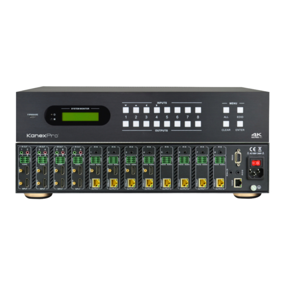
1) Confirm if the product and the accessories are all included, if not, please contact with the dealers. 2) This matrix switcher does not include any receivers, please order the receivers separately by contacting your AV dealer or KanexPro directly. 2. Product Appearance of the KanexPro 8x8 Matrix Switcher 2.1 Front Panel... - Page 8 Important: This matrix switcher does not include any receivers, please order the receivers separately by contacting your AV dealer or KanexPro directly. Referring part # HDBASE70POER for optional HDBaseT receivers which are powered over Ethernet from the Matrix switcher.
-
Page 9: Rear Panel
IR IN: Connect with IR receiver (with carrier), 8 in total, correspond to the 8 IR OUT, cannot be switched separately. It makes up an IR bi-directional transmission OUTPUTS with the IR OUT on the corresponding far-end receiver. RS232: 3-pinpluggable terminal blocks, 8 in total, MX-HDBASE8X8-4K KanexPro.com... -
Page 10: System Connection
1) System should be installed in a clean environment and has a prop temperature and humidity. 2) All of the power switches, plugs, sockets and power cords should be insulated and safe. 3) All devices should be connected before power on. MX-HDBASE8X8-4K KanexPro.com... -
Page 11: Connection Diagram
7) The switcher can collect IR signal sent by the included IR remote via its built-in IR sensor or through external IR receiver connected to the IR IN/ IR EYE/ IR ALL IN port. The IR signal can be transmitted bi-directionally between the switcher and far-end receivers. MX-HDBASE8X8-4K KanexPro.com... -
Page 12: Connection With Hdmi Twisted Pair Poc Receiver
The operation examples are showed in 2.1 Front Panel. Here we make a brief introduction to the system operations. 4.1.1 Switching I/O connection To convert one input to an output: Operation: “input”+“output”+“ENTER” Example: input 1 to output 2 MX-HDBASE8X8-4K KanexPro.com... -
Page 13: Edid Management
One input port learns the EDID data of one output port Operation: Press “EDID”, “INPUTS”+“OUTPUTS”+“ENTER”. Example: Input 2learns EDID data from output 4 Ø All input ports learn EDID data from one output port Operation: Press “EDID”, “ALL”+“OUTPUTS”+“ENTER” Example: All input ports learn EDID data from output 4 MX-HDBASE8X8-4K KanexPro.com... -
Page 14: Inquiry
4.1.3 Inquiry Ø Check status Press and hold the button “ENTER” for 3 seconds, it will enter into system inquiry menu. Use Left and Right direction button to navigate checking the previous/next items. Function Items Example Description MX-HDBASE8X8-4K KanexPro.com... -
Page 15: Clear Operation
“ENTER” to carry it on. When you press it, the matrix will return to the previous status. 4.2 IR Control By using IR & HDBaseT transmission technology, the switcher has some functions as follows: MX-HDBASE8X8-4K KanexPro.com... - Page 16 4K HDBaseT™ 8x8 Matrix Switcher 1) Control far-end output device from local. 2) Control local input/output device remotely. 3) Control the 4K HDBaseT 8x8 Matrix Switcher locally/remotely. MX-HDBASE8X8-4K KanexPro.com...
-
Page 17: Usage Of Ir Remote
RS232, and 1 AUDIO outputs, and channel1~4have HDMI outputs. Note: With this IR remote, the matrix switcher can be controlled with the built-in IR, the extended IR receiver connected to the “IR EYE”/”IR ALL IN” and the IR receiver on the far-end receiver. MX-HDBASE8X8-4K KanexPro.com... -
Page 18: Ir Operations
Only if the IR receiver connected to IRALL IN port of the matrix is with IR carrier, can the received IR signal be transferred to IR OUT port of the matrix. If the IR receiver connected with HDBaseT receiver or IR ALL IN port of the matrix is MX-HDBASE8X8-4K KanexPro.com... - Page 19 Note: The IR receiver connected to IR IN must be with IR carrier The IR signal received from IR ALL IN port will be transmitted to all the eight far-end HDBaseT receivers connected to HDBaseT ports of the matrix switcher. See below: MX-HDBASE8X8-4K KanexPro.com...
- Page 20 INPUT INPUT INPUT OUTPUT 1 OUTPUT 2 OUTPUT 3 OUTPUT 4 OUTPUT 5 OUTPUT 6 OUTPUT 7 OUTPUT 8 Revceiver HDTV HDBT IN HDMI OUT IR IN IR OUT RS232 HDTV IR Remote Control local device from remote MX-HDBASE8X8-4K KanexPro.com...
-
Page 21: Rs232 Control
RS232 control software. Double-click the software icon to run this software. Here we take the software CommWatch.exeas example. The icon is showed as below: The interface of the control software is showed as below: MX-HDBASE8X8-4K KanexPro.com... - Page 22 Command Sending area Command Sending area Please set the parameters of COM number, bound rate, data bit, stop bit and the parity bit correctly, only then will you be able to send command in Command Sending Area. MX-HDBASE8X8-4K KanexPro.com...
-
Page 23: Rs232 Communication Commands
Stop bit: 1 Parity bit: none Command Function Feedback Example System Commands /*Type; Inquire the models information. MX-HDBASE8X8-4K /%Lock; Lock the front panel buttons on the Matrix. System Locked! Unlock the front panel buttons on the /%Unlock; System Unlock! Matrix. - Page 24 HDBaseT receivers STANDBY. STANDBY press other buttons or send other commands to start.) Audio/[X]:[Y]. Select HDMI audio or analog audio as X=1~8, Y=0 (HDMI Audio/[X]:[Y]. audio source for output 1~8. audio) or 1 (Analog audio). MX-HDBASE8X8-4K KanexPro.com...
- Page 25 X=9, enable all the 8 ports. Disable HDMI audio output of port x. DigitAudio OFF with DigitAudioOF l X=1, 2, 3, 4, 5, 6, 7, 8, disable this F[x]. port. x=1~8 or ALL l X=9, disable all the 8 ports. MX-HDBASE8X8-4K KanexPro.com...
- Page 26 G & O are for port 7. H & P are for port 8. X is for bound rate, its value ranges from 1 to 7 (1--2400, 2--4800, 3--9600, 4--19200,5--38400, 6—57600, 7--115200) ***** is for data (max 48 Byte) MX-HDBASE8X8-4K KanexPro.com...
- Page 27 EDID file (.bin file). Operations will be canceled after 10 seconds. Please cut off all connections of HDBaseT ports. Set the EDID data of input port [x] to built-in EDID No.[y]. EDID/[x]/[y]. EDID/[x]/[y] [y]=1~6, correspond to the 6 embedded EDID data MX-HDBASE8X8-4K KanexPro.com...
- Page 28 Check the command sent by port 5 when Port 5:data when %9955. PWON. PWON Check the command sent by port 6 when Port 6:data when %9956. PWON. PWON Check the command sent by port 7 when Port 7:data when %9957. PWON. PWON MX-HDBASE8X8-4K KanexPro.com...
- Page 29 System Locked/ %9961. Check the system locking status. Unlock! STANDBY/PWON/ %9962. Check the status while in standby mode. PWOFF Check the working mode of infrared Carrier native/ Force %9963. carrier. carrier IP:192.168.0.178 %9964. Check the IP address. (default) MX-HDBASE8X8-4K KanexPro.com...
- Page 30 Check the HDCP status of the outputs. 5 6 7 8 HDCP N N Y Y 1 2 3 4 1 2 3 4 %9975. Check the I/O connection status. 5 6 7 8 5 6 7 8 MX-HDBASE8X8-4K KanexPro.com...
-
Page 31: Rs232 Control Modes
PC (RS232 command can be transmitted to the switcher via the twisted pair). By using RS232 control software and with right specification settings, you are able to control the switcher. l Control the KanexPro 8x8 Matrix Switcher from local MX-HDBASE8X8-4K KanexPro.com... -
Page 32: Control 3Rd-Party Device From Local
IR OUT RS232 HDMI OUT Control the KanexPro 8x8 Matrix Switcher from remote 4.3.6 Control 3rd-Party Device from Local Connect the 9 pin female RS232 port of the switcher with PC, by using the RS232 command “/+[Y]/[X]:******.”, you are able to control the 3rd-party device connected with the HDBaseT receiver. -
Page 33: Bi-Directional Rs232 Control
OUTPUT 3 OUTPUT 4 OUTPUT 5 OUTPUT 6 OUTPUT 7 OUTPUT 8 Receiver HDBT IN HDMI OUT IR IN IR OUT RS232 3rd party Control far-end device from local l Control the KanexPro 8x8 Matrix Switcher from remote MX-HDBASE8X8-4K KanexPro.com... -
Page 34: Tcp/Ip Control
IR IN IR OUT RS232 HDMI OUT Control the KanexPro 8x8 Matrix Switcher from remote 4.4 TCP/IP Control 4.4.1 Control Modes TCP/IP default settings: IP is 192.168.0.178, Gateway is 192.168.0.1, and Serial Port is 8080. IP & Gateway can be changed as you need, Serial Port cannot be changed. - Page 35 Step1. Connect the TCP/IP port of the switcher to Ethernet port of PC with twisted pair. Step2. Set the PC’s network segment to the same as the switcher’s. Please remember the PC’s original network segment. Step3. Set the switcher’s network segment to the same as the router. MX-HDBASE8X8-4K KanexPro.com...
-
Page 36: Gui For Tcp/Ip Control
Log in as admin can access more configuration interfaces than user. Enter username and the right password. Here is a brief introduction to the interfaces. Main: Interface shown after logging in, provide intuitive I/O connection switching. See the screenshot below: MX-HDBASE8X8-4K KanexPro.com... - Page 37 Users: Display or modify credential settings, front panel lock, and GUI version. If there is any modification, press Save to restore the settings, or press Cancel to withdraw. Interface: Set title bar label, LCD readout, and button labels, press Save to save the MX-HDBASE8X8-4K KanexPro.com...
- Page 38 4K HDBaseT™ 8x8 Matrix Switcher settings Configuration: Set HDCP Cmpliance status for every input, and manage EDID. See the screenshot below: Network: Inquire and configure network settings including MAC address, IP address, subnet mask, and Gateway MX-HDBASE8X8-4K KanexPro.com...
-
Page 39: Gui Update
Step1. Copy the upgrade software and the latest upgrade file (.bin) to PC. Step2. Connect the USB ports of the switcher and the PC via USB cable. Step3. Double-click the update software icon (see as below). MX-HDBASE8X8-4K KanexPro.com... - Page 40 It will enter the upgrade interface shown as below: Step4. Click Connect USB. Step5. Click Open to load the upgrade file, and then click Updata to start firmware upgrading. Note: To ensure available control, the COM number of the PC should be 1~9. MX-HDBASE8X8-4K KanexPro.com...
-
Page 41: Specification
8 IR OUT (green and red) 8 IR IN (black) 1 IR EYE (black) Control Ports Panel Control Front panel buttons 1 IR ALL IN (black) 1 TCP/IP (female RJ45) 1 RS232 (9 pin female) 8 RS232s (3-pin MX-HDBASE8X8-4K KanexPro.com... - Page 42 Extended IR receiver Control TCP/IP Works with In-built web GUI Control General Power Power 100V~240V AC 103W (full load) Supply Consumption Reference Temperature -10 ~ +40℃ 10% ~ 90% Humidity Dimension x 87.8 x 380 mm Weight 5.4Kg (W*H*D) MX-HDBASE8X8-4K KanexPro.com...
-
Page 43: Troubleshooting & Maintenance
IR remote pointing at the IR receiver IR receiver. The IR receiver connected Change for an IR receiver to IR IN/ IR ALL IN port is with carrier. not with carrier MX-HDBASE8X8-4K KanexPro.com... - Page 44 If your problem persists after following the above troubleshooting steps, seek further help from authorized dealer or our technical support at 888-975-13668 or visit: kanexpro.com for more details on that product. MX-HDBASE8X8-4K KanexPro.com...
-
Page 45: After-Sales Service
Product version and name. l Detailed failure situations. l The formation of the cases. Remarks: For any questions or problems, please try to get help from your local distributor or AV dealer. MX-HDBASE8X8-4K KanexPro.com... - Page 47 Brea, California KanexPro.com MPN: MX-HDBASE6X6-4K HDMI® and HDBaseT™ are trademarks or registered trademarks of HDMI Licensing LLC & HDBaseT Alliance respectively in the United States and other countries. KanexPro is a trademark of Apogee Inc., registered trademarks in the US.
Need help?
Do you have a question about the MX-HDBASE8X8-4K and is the answer not in the manual?
Questions and answers