
Related Manuals for Toa NX-300


Summary of Contents for Toa NX-300
- Page 1 INSTALLATION SETUP MANUAL NETWORK AUDIO ADAPTER NX-300 Than you for purchasing T s et or udio dapter. lease carefully follo the instructions in this manual to ensure long trouble free use of your e uipment.
-
Page 2: Table Of Contents
..................3. BEFORE SETUP ................... ddresses and nstallation ocations ............nput evel d ustment ..................Chapter 3 SYSTEM SETTINGS (NX-300 SETTING SOFTWARE) 1. GENERAL DESCRIPTION ..............inder and etting oft are ........... . . bout et or ettings .................. - Page 3 . . hanging the nit etting alues elated to the et or ....... . aving the nit etection ist ata ..............6. STARTING THE NX-300 SETTING SOFTWARE ....7. OPERATION FROM THE SYSTEM EDITING SCREEN ..reating a e ystem ..................
- Page 4 15. AUDIO FILE SETTINGS ............... . . ploading udio iles ..................eleting udio iles ..................16. OPERATIONS ACCESSIBLE FROM THE SETUP EDITING SCREEN MENU ................... . . aving the nit etting iles ................hanging the ystem ame and ass ord ..........
- Page 5 ..................... eflecting hanged ettings nit estart ............. Chapter 5 SETTINGS NECESSARY WHEN USING THE NX-300 OPERATION SOFTWARE 1. NX-300 OPERATION SOFTWARE SUMMARY ......2. STARTUP AND INITIAL SCREEN ............. 3. OPERATION SCREEN DESCRIPTION ..........utton creen ....................
- Page 6 3. LEVEL DIAGRAM ..................loc iagram ....................evel iagram ....................bout etting alues and udio nput evel d ustments ....... 4. IF A FAILURE IS DETECTED ............... 5. SPECIFICATIONS ..................
-
Page 7: Chapter 1 System Summary
Chapter 1 SYSTEM SUMMARY... -
Page 8: General Description
SYSTEM SUMMARY Chapter 1 1. GENERAL DESCRIPTION TOA s NX-300 Net ork Audio Adapter is specially de eloped to transmit high- uality audio signals o er net orks such as AN or nternet in real time. [Audio Signal Flow Chart]... -
Page 9: Nomenclature And Functions
8. Run indicator (Green) gure belo . The le el increases ith clock ise lashes hen the NX-300 is operating normally, rotation and decreases ith counterclock ise and either continuously lights or e tinguishes rotation. - Page 10 15. Network connection terminal A ground loop can potentially be created onnects to 10 AS -T or 100 AS -TX net orks. the NX-300 is connected to other e uipment, thernet ack resulting in a hum noise. round loops can be...
-
Page 11: Setting Task Flows
• The NX-300 Setting Soft are can perform settings for multiple NX-300 units connected to the same net ork. • The NX-300 inder is used to detect NX-300 units on a net ork and change net ork settings. • The NX-300 Operation Soft are enables the to remotely operate the NX-300 to make broadcasts. -
Page 12: Chapter 2 Installation And Connection
Chapter 2 INSTALLATION AND CONNECTION... -
Page 13: Connections
Connect the AC adapter* to the unit’s AC adapter terminal. Pinch the cord with a clamp and securely x it. * Use the optional AC adapter AD-246 or the equivalent. As for the usable adapter, consult your TOA dealer. AC adapter AD-246... -
Page 14: Terminal Onnections
INSTALLATION AND CONNECTION Chapter 2 1.2. Terminal Connections 1.2.1. Network connections The NX-300 automatically distinguishes bet een 10 AS -T and 100 AS -TX net orks, and establishes a connection. or this connection, use a straight ategory or greater AN thernet cable tted connector. - Page 15 [When transmitting audio from one sound source to multiple channels] To use the same sound source bet een channels or NX-300 units through the NX-300 s audio input terminal, perform connections as sho n belo using the bridge out unction .
- Page 16 INSTALLATION AND CONNECTION Chapter 2 1.2.3. Connections to control input and output terminals onnect the control input and output terminals of all other connected units using control lines. Note e sure to connect only these control lines to other unit’s control input terminals. onnecting in parallel ith control lines from other e uipment may cause the unit to malfunction.
- Page 17 , for hich shielded t isted pair cables shorter than 10 m 3 . 1 ft should be used. • onnect the cable s shielded ire to the NX-300 s signal N terminal. Output control terminals for which failure detection is performed. To other unit's control output ±...
-
Page 18: Emovable Terminal Lug Onnection
INSTALLATION AND CONNECTION Chapter 2 1.3. Removable Terminal Plug Connection Step 1. iring the supplied remo able terminal plug. [Recommended type of screwdriver ] 1-1. Loosen the terminal screws to insert the wire. 1-2. Tighten the terminal scre s. Blade width* nsure that the ire does not break free pulled. -
Page 19: Installation
2.1.2. When mounting 2 units se the optional - hard are set hen mounting units. Note The NX-300 and other e uipment cannot be linked together and mounted in a rack using the 3 x 14 tapping screw * omponent parts of NX-300 NX-300... - Page 20 YC-850 Wall mounting bracket (Option) Machine screw M3 x 6 (supplied with the YC-850) Step 2. ount the NX-300 on the all. Notes • se appropriate scre s for the construction of all. • 3. 0 ood scre s are supplied ith the [ Wall mounting dimensions ] 225.5 mm (8.88")
- Page 21 INSTALLATION AND CONNECTION Chapter 2 2.3. Desk-Top Installation hen installing the NX-300 on a desk, secure the supplied plastic feet to the unit s bottom using the supplied machine screws. M3 x 8 machine screw (accessory) Plastic foot (accessory)
-
Page 22: Before Setup
An address inherently assigned to and uni ue to a net orking de ice, consisting of 1 hyphenated alphanumeric characters. NETWORK AUDIO ADAPTER NX-300 INPUT VOLUME OUTPUT... -
Page 23: Chapter 3 System Settings (Nx-300 Setting Software)
Chapter 3 SYSTEM SETTINGS (NX-300 SETTING SOFTWARE) -
Page 24: General Description
• The soft are can also handle settings les for multiple systems. 1.1.3. Devices that can be set up The NX-300 Setting Software can also be used to set up the NX-100 and NX-100S units in the same manner. Therefore, e en for combined systems con gured ith the NX-300, NX-100 and NX-100S units, settings can be performed using only the NX-300 Setting Software. -
Page 25: Software Installation
[Update information] • To con rm the NX-300 rm are ersion or to update the rm are, use the bro ser on the See p. 4-19, "SYSTEM MANAGEMENT." • To con rm the NX-300 soft are ersion, use the elp menu of the soft are. - Page 26 SYSTEM SETTINGS (NX-300 SETTING SOFTWARE) Chapter 3 2.4. NX-300 Setting Software Installation Step 1. pand the ip le do nloaded from TOA product data download site and double-click on the resulting "setup. The installer will start up. Step 2. Click the Next button.
- Page 27 The "Installation Complete" screen is displayed when the installation is correctly completed. Step 7. Click the Close button. 2.5. When NX-300 Software Uninstallation Select [Control Panel] [Programs and Features] to delete the NX-300 Software program.
- Page 28 SYSTEM SETTINGS (NX-300 SETTING SOFTWARE) Chapter 3 2.6. Folder Configuration The NX-300 Software is installed in the following folders by default: 32 bit OS: C:\Program Files\TOA\NX-300 64 bit OS: C:\Program Files (x86)\TOA\NX-300 The software settings files are saved to the following folders: C:\ProgramData\TOA\NX-300 The configuration of the folders is as follows.
-
Page 29: Software Configuration And Setting Items
Chapter 3 3. SOFTWARE CONFIGURATION AND SETTING ITEMS The use of both the NX-300 Setting Software and the NX-300 Finder allows settings of all items, including device detection and network settings. When installing the system, first set all items using these software programs. -
Page 30: Setting Procedure
• Sa e the net ork setting data in ile format of the unit list information arbitrary name . ml . (2) System Setting Create a new system with the NX-300 Setting Software and read the unit list information created in Item (1) above, then set up all the items other than network settings. - Page 31 Also be sure to save backup copies. (3) Unit Scanning (Network Setting) • After installing the system s NX-300 Setting Soft are on-site, copy the contents of the data folder saved in Step (2) above to the data folder.
-
Page 32: Starting The Nx-300 Finder
Detect all units connected to the local network. Note The NX-300 Setting Software cannot be used to write settings information to units if their IP addresses are not correctly set using the NX-300 Finder or browser. Step : Double-click the shortcut for the NX-300 Finder which was created on the desktop when installed. - Page 33 SYSTEM SETTINGS (NX-300 SETTING SOFTWARE) Chapter 3 5.2. Menu 5.2.1. File Sa e S Sa ed to the X format le sa ed in Sa e As. Save As (A): Saves information on the detected unit to the PC in the unit list information format ("arbitrary name".xml).
-
Page 34: Etecting Nits
Setting Software. • nits may not be detected if the re all function of the hich the NX-300 inder is installed is enabled. n such cases, change the re all settings and remo e the block to the NX-300 inder. 3-12... -
Page 35: Creen Escription
Unit Information list Displays information on the unit selected in the detected unit list. Detected Unit list Displays all units detected with the NX-300 Finder. [Settings items for the unit information list] 1. MAC address 5. Web port Displays the detected unit’s MAC address. - Page 36 SYSTEM SETTINGS (NX-300 SETTING SOFTWARE) Chapter 3 5.6. Changing the Unit Setting Values Related to the Network nit setting alues can be changed indi idually. Step 1. Click the cell on the detected unit list to be changed. The unit information list is placed in a mode that allows the unit information list to be input.
- Page 37 Chapter 3 5.7. Saving the Unit Detection List Data Save the unit detection results to the PC. nit settings can be ef ciently done by reading the detection results using the NX-300 Setting Soft are. p. 3-20, "SETUP EDITING SCREEN.") Step 1.
-
Page 38: Starting The Nx-300 Setting Software
SYSTEM SETTINGS (NX-300 SETTING SOFTWARE) Chapter 3 6. STARTING THE NX-300 SETTING SOFTWARE Step : Double-click the shortcut for the NX-300 Setting Software which was created on the desktop when installed. Or directly double-click the "NX-300SettingSoftware.exe" software created in the installed folder. - Page 39 SYSTEM SETTINGS (NX-300 SETTING SOFTWARE) Chapter 3 7.1. Creating a New System A new system is created. Step 1. Click the New system button on the system editing screen. The new system creation screen is displayed. Step 2. Enter a system name and password.
-
Page 40: Diting Egistered Ystems
SYSTEM SETTINGS (NX-300 SETTING SOFTWARE) Chapter 3 7.2. Editing Registered Systems Edit the system registered in the NX-300 Setting Software. Step 1. Click the System selection button on the system editing screen. The screen for selecting the system is displayed. -
Page 41: Eleting Egistered Ystems
SYSTEM SETTINGS (NX-300 SETTING SOFTWARE) Chapter 3 7.3. Deleting Registered Systems Delete the system registered in the NX-300 Setting Software’s data folder. Click the "System deletion" button on the system editing screen to display the screen for selecting the existing system. -
Page 42: Setup Editing Screen
2. General settings button 4. Import button sed to perform settings related to the entire Capable of reading settings by selecting the XML- system. Clicking this button displays the overall formatted le stored using the NX-300 inder. (See p. 3-26.) setting screen. 3-20... - Page 43 SYSTEM SETTINGS (NX-300 SETTING SOFTWARE) Chapter 3 5. Model 12. Broadcast spec tab (See p. 3-35.) Displays the list of unit model names registered sed to set broadcast uality. in the system. 13. Pattern tab 6. Name sed to set each unit s broadcast and contact Displays the list of unit names registered in the bridge destinations.
- Page 44 Options: Allows access to network settings. 8.2.3. Help Toa data library: Starts the web browser and accesses the TOA product data download site. About: Displays the software’s version information. 3-22...
-
Page 45: System Configuration Settings
Step 1. Click on the Import button on the setup editing screen. A dialog for le selection is displayed. Step 2. Select the unit selection list data (XML format) saved with the NX-300 Finder and click on the Open button. - Page 46 SYSTEM SETTINGS (NX-300 SETTING SOFTWARE) Chapter 3 9.2. Adding Units to the Unit List Step 1. Click the Add button on the setup editing screen. A dialog for device addition is displayed. Step 2. Enter the number of units to be added and click the OK button.
- Page 47 SYSTEM SETTINGS (NX-300 SETTING SOFTWARE) Chapter 3 9.3. Deleting Units from the Unit List Step 1. Check the unit to be deleted. All units can be simultaneously checked using the Check all button. All displayed units can be simultaneously unchecked ith the ncheck all button.
-
Page 48: General System Settings
Step 1. Click the General Settings button on the setup editing screen. The general settings screen is displayed. This setting is only possible when an NX-300 unit is detected in the system. Step 2. Set each item. 1. Same priority broadcast Select the preferred operation when a new broadcast with the same priority is made while a broadcast is currently in progress. - Page 49 SYSTEM SETTINGS (NX-300 SETTING SOFTWARE) Chapter 3 4. Surveillance Selects whether to enable or disable the surveillance function. Enables failure detection. OFF: Disables failure detection. 5. NTP Time is corrected using the NTP client function. A time signal is acquired once a day from the NTP server at startup, and time correction terminates when time synchroni ation is successful.
- Page 50 31 characters can be used. 2. IP address Enter the IP address of the unit. When the detected unit list data is imported after the IP address is set with the NX-300 Finder, an assigned IP address is displayed.
- Page 51 Start port No. + 1 Contact bridge Start port No. + 2 Broadcast Control and Contact Bridge are used to control operations between the NX-300 and NX-100/ NX-100S units. se ontrol to control operations using the NX-300 Operation Soft are.
- Page 52 SYSTEM SETTINGS (NX-300 SETTING SOFTWARE) Chapter 3 7. NAPT When connecting a PC to the NX-300 using the global IP address, mark the [Enable] checkbox to make the items from Net ork port 1 a ailable for input. 8. Network ID...
- Page 53 SYSTEM SETTINGS (NX-300 SETTING SOFTWARE) Chapter 3 11. WAN UDP Port Set the start port number to be used for each protocol as ie ed from the AN side. [Start port No.] nter the rst number of the unit s ports other than those noted abo e.
- Page 54 31 characters can be used. 2. IP address Enter the IP address of the unit. When the detected unit list data is imported after the IP address is set with the NX-300 Finder, an assigned IP address is displayed. 3. Subnet mask Enter the subnet mask.
- Page 55 SYSTEM SETTINGS (NX-300 SETTING SOFTWARE) Chapter 3 5. TCP port esignate the ports to be used by the eb ser er and the rst number of other T ports. The range of port numbers that can be set is 1 [Web server] nter the eb ser er port number.
- Page 56 SYSTEM SETTINGS (NX-300 SETTING SOFTWARE) Chapter 3 10.2. External Server Settings (NX-300 only) Necessary external servers can be set. Step 1. Select the unit to be set from the unit list on the setup editing screen. Step 2. Select the "Network" tab and click the Others button.
-
Page 57: Roadcast Pec Ettings
Step 1. Select the unit to be set from the unit list. Step 2. Select the NX-300 Setting Software’s "Broadcast spec" tab. The broadcast spec setting screen is displayed. Step 3. Set each item. - Page 58 SYSTEM SETTINGS (NX-300 SETTING SOFTWARE) Chapter 3 2. Parameters for each channel Select the channel to be set and set each parameter. [Transmission Sampling frequency (kHz)] Select the sampling fre uency for transmission , 1 , 3 , The higher the number, the more the sound uality is impro ed, ho e er the utili ed band idth also expands.
- Page 59 Note Set different addresses for Multicast Addresses 1 and 2. When setting, take care that Addresses 1 and 2 do not duplicate the multicast addresses of other NX-300 units connected to the same network. 5. Enable volume control schedule (NX-300 only) This function adjusts the audio output level provided during the preset time period.
-
Page 60: Pattern Settings
SYSTEM SETTINGS (NX-300 SETTING SOFTWARE) Chapter 3 11. PATTERN SETTINGS Selecting the Pattern tab on the setup editing screen displays the pattern setting screen. Control pattern, Broadcast pattern, and Contact bridge pattern buttons allow switching between the Control pattern, Broadcast... -
Page 61: Attern Etting Ummary
Chapter 3 11.1. Pattern Setting Summary 11.1.1. Devices that require pattern settings Pattern settings are performed for devices that make broadcasts from either the control input or the NX-300 Operation Software. When starting broadcasts from the control input, select Control Pattern. -
Page 62: Roadcast Attern Ettings
The broadcast pattern represents a combination of broadcasting direction and connection destinations which are set in units that make broadcasts activated from the NX-300 Operation Software. The Broadcast pattern can be set for local broadcasts that do not use a network or a combination that allows single stream broadcasts. - Page 63 SYSTEM SETTINGS (NX-300 SETTING SOFTWARE) Chapter 3 11.2.2. Creating a new broadcast pattern Step 1. Click the Add Broadcast pattern button. The ne pattern can be edited on the editing eld. (See p. 3-44, "Broadcast pattern setting items.") Step 2. Set each item.
- Page 64 SYSTEM SETTINGS (NX-300 SETTING SOFTWARE) Chapter 3 11.2.3. Changing the broadcast pattern setting contents Step 1. Select the broadcast pattern to be changed on the broadcast pattern list. The change can be edited on the editing eld. (See p. 3-44, "Broadcast pattern setting Step 2.
- Page 65 SYSTEM SETTINGS (NX-300 SETTING SOFTWARE) Chapter 3 11.2.4. Deleting the broadcast pattern Step 1. Select the broadcast pattern to be deleted on the broadcast pattern list. Step 2. Click the Delete Broadcast patterns button. A con rmation dialog is displayed.
- Page 66 SYSTEM SETTINGS (NX-300 SETTING SOFTWARE) Chapter 3 11.2.5. Broadcast pattern setting items 1. No. Select the broadcast pattern number. 2. Pattern name Enter the broadcast pattern name (up to 31 characters). 3. Direction Select the direction in which broadcasts are to be made.
- Page 67 SYSTEM SETTINGS (NX-300 SETTING SOFTWARE) Chapter 3 Step 2. Select the audio le. 2-1. Selecting from the audio le number hen unable to connect to the unit lick Select from audio le number. and select the number from the pull-do n list.
- Page 68 11.3. Contact Bridge Pattern Settings The contact bridge pattern represents a control output combination to be set in units that make broadcasts activated from the control input or NX-300 Operation Software. p to connection destinations can be set in a contact bridge pattern.
- Page 69 SYSTEM SETTINGS (NX-300 SETTING SOFTWARE) Chapter 3 11.3.2. Creating a new contact bridge pattern Step 1. Click the Add contact bridge pattern button. The ne pattern can be edited on the editing eld. (See p. 3-50, "Contact bridge pattern setting items.")
- Page 70 SYSTEM SETTINGS (NX-300 SETTING SOFTWARE) Chapter 3 11.3.3. Changing the contact bridge pattern setting contents Step 1. Select the contact bridge pattern to be changed on the Contact Bridge Pattern list. The change can be edited on the editing eld.
- Page 71 SYSTEM SETTINGS (NX-300 SETTING SOFTWARE) Chapter 3 11.3.4. Deleting the contact bridge pattern Step 1. Select the contact bridge pattern to be deleted on the Contact Bridge Pattern list. Step 2. Click the Delete contact bridge pattern button. A con rmation dialog is displayed.
- Page 72 SYSTEM SETTINGS (NX-300 SETTING SOFTWARE) Chapter 3 11.3.5. Contact bridge pattern setting items 1. No. Select the contact bridge pattern number. 2. Pattern name Set the contact bridge pattern name (up to 31 characters). 3. Contact bridge Set the unit’s control output number to be activated.
-
Page 73: Ontrol Attern Ettings
SYSTEM SETTINGS (NX-300 SETTING SOFTWARE) Chapter 3 11.4. Control Pattern Settings atterns that combine both broadcast patterns and contact bridge patterns can be set. p to broadcast patterns and up to transmission patterns and reception or local patterns can be set. - Page 74 SYSTEM SETTINGS (NX-300 SETTING SOFTWARE) Chapter 3 11.4.2. Creating a new control pattern Step 1. Click the Add control pattern button. The ne pattern can be edited on the editing eld. (See p. 3-55, "Control pattern setting items.") Step 2. Set each item.
- Page 75 SYSTEM SETTINGS (NX-300 SETTING SOFTWARE) Chapter 3 11.4.3. Changing the control pattern setting contents Step 1. Select the control pattern to be changed on the control pattern list. The change can be edited on the editing eld. (See p. 3-55, "Control pattern setting items.") Step 2.
- Page 76 SYSTEM SETTINGS (NX-300 SETTING SOFTWARE) Chapter 3 11.4.4. Deleting the control pattern Step 1. Select the control pattern to be deleted on the control pattern list. Step 2. Click the Delete Control patterns button. A con rmation dialog is displayed.
- Page 77 SYSTEM SETTINGS (NX-300 SETTING SOFTWARE) Chapter 3 11.4.5. Control pattern setting items 1. No. Select the control pattern number. 2. Pattern name Set the control pattern name (up to 31 characters). 3. Priority Set the priority le el of the control pattern. 1...
-
Page 78: Control Input Settings
SYSTEM SETTINGS (NX-300 SETTING SOFTWARE) Chapter 3 12. CONTROL INPUT SETTINGS 12.1. For the NX-300 Units Step 1. Select the units to set from the nit list on the setup editing screen. Step 2. Select the Control I/O tab and click on the Control input button. - Page 79 SYSTEM SETTINGS (NX-300 SETTING SOFTWARE) Chapter 3 4. Type Select the type of control input. Momentary: While the input is ON, the designated control pattern is kept activated. The activation stops when the input becomes OFF. Latch: If the input is ON, the designated control pattern is activated and this condition lasts even if the input becomes OFF.
- Page 80 Chapter 3 12.2. For the NX-100/100S Units The control inputs of both NX-100 and NX-100S units can be set using the NX-300 Setting Software Step 1. Select the units to set from the unit list on the setup editing screen.
- Page 81 SYSTEM SETTINGS (NX-300 SETTING SOFTWARE) Chapter 3 3. Type Select the type of control input. Momentary: While the input is ON, the designated control pattern is kept activated. The activation stops when the input becomes OFF. Latch: If the input is ON, the designated control pattern is activated and this condition lasts even if the input becomes OFF.
- Page 82 To select, mark the desired control output number checkbox located on the right of the unit name indication. The total number of selected units is displayed at the right of the "Number of units" indicator. Note NX-100 and NX-100S units cannot be used to control NX-300 unit control outputs 9 and 10. 3- 0...
-
Page 83: Control Output Settings
Step 3. Set each item. 1. Control output No. Click the control output number to be set. Selectable in the range of 1 10 for the NX-300 units and 1 for the NX-100 and NX-100S units. 2. Enable Set to be checked by default. - Page 84 Control output is activated while the error indicator lights. 4. Type Select the type of control output. Selectable content may differ depending on the units to be set. • f setting an NX-300 unit ontrol Output is ed to omentary.
-
Page 85: Serial Bridge Setting (Nx-100 Only)
SYSTEM SETTINGS (NX-300 SETTING SOFTWARE) Chapter 3 14. SERIAL BRIDGE SETTING (NX-100 ONLY) Serial bridge settings can only be made when setting the NX-100 unit. Step 1. Select the device to be set on the setup editing screen. Step 2. Select the "Serial" tab. - Page 86 SYSTEM SETTINGS (NX-300 SETTING SOFTWARE) Chapter 3 3. Connection destination Select the unit to be connected. Note Selection is only possible hen T lient or is checked in the protocol settings. 4. Baud rate Select 00 , 1 00 , 3 00 , 00 or 11 00 .
-
Page 87: Audio File Settings
SYSTEM SETTINGS (NX-300 SETTING SOFTWARE) Chapter 3 15. AUDIO FILE SETTINGS Audio les can be uploaded to the NX-300 unit or subse uently deleted. onditions for adding an audio le are as follows: File format: Sampling fre uency , 1 , 3 , and... - Page 88 SYSTEM SETTINGS (NX-300 SETTING SOFTWARE) Chapter 3 Step 4. Select the audio le and click the Open button. The list of audio les to be uploaded is displayed. Step 5. lick the pload button. The audio le is uploaded to the NX-300 unit.
-
Page 89: Eleting Udio Iles
SYSTEM SETTINGS (NX-300 SETTING SOFTWARE) Chapter 3 15.2. Deleting Audio Files Step 1. Select the unit to be set from the unit list on the setup editing screen. Step 2. Select the Audio ile tab and click the elete audio le button. -
Page 90: Operations Accessible From The Setup Editing Screen Menu
16. OPERATIONS ACCESSIBLE FROM THE SETUP EDITING SCREEN MENU 16.1. Saving the Unit Setting Files Sa e the unit setting le to the speci ed location. * NX-300 Setting Software’s data folder. The save location cannot be manually designated. Select "File" "Save" from the menu. - Page 91 SYSTEM SETTINGS (NX-300 SETTING SOFTWARE) Chapter 3 16.3. Changing the System Password The current system’s password can be changed. Step 1. Select "File" "Change password" from the menu. A dialog for changing the password is displayed. Step 2. Enter the old password and a new password.
- Page 92 Step 3. Select the unit to be uploaded from the unit list and click the OK button. Note nit setting le upload takes some time. Take care to ne er s itch off the NX-300, NX-100, or NX-100S po er during the upload.
- Page 93 Step 2. Select the unit to be downloaded from the unit list and click the OK button. After download, the results of a comparison of the new unit settings with those retained by the NX-300 Setting Software are shown. If both settings match, the "No differences" indicator is displayed. If they do not match, the "Differences exist"...
- Page 94 "About" from the menu. [Version upgrade information] The latest ersions of the NX-300 rm are, NX-300 Soft are NX-300 Setting Soft are, NX-300 inder, and NX-300 Operation Software), and manuals (NX-300 Installation Setup Manual and NX-300 Operations manual) can be found on the TOA Product Download site (http://www.toa-products.com/international). Access the...
-
Page 95: System Setting Examples
Three switches are required to execute all application examples shown in this section. Install the NX-300 Finder, NX-300 Setting Software and NX-300 Operation Software in advance. (See p. 3-3, "SOFTWARE INSTALLATION.") Stations A, B... - Page 96 17.2.1. Setting procedure Step 1. Start the NX-300 Finder with the central station’s PC and set the IP address of the NX-300 unit (For setting procedures, see p. 3-10, "STARTING THE NX-300 FINDER.") installed at each station.
- Page 97 SYSTEM SETTINGS (NX-300 SETTING SOFTWARE) Chapter 3 Step 3. As in Step 2, set contact bridge patterns for the NX-300 unit installed at the central station using the NX-300 Setting Software as follows. Pattern name Activation of Station A’s Amp.
- Page 98 SYSTEM SETTINGS (NX-300 SETTING SOFTWARE) Chapter 3 Step 4. As in Step 2, set control patterns for the NX-300 unit installed at the central station using the NX-300 Setting Software as follows. Pattern name Announcement to Station A Priority Broadcast pattern Mic.
- Page 99 SYSTEM SETTINGS (NX-300 SETTING SOFTWARE) Chapter 3 Step 5. As in Step 2, perform contact input settings for the NX-300 unit installed at the central station using the NX-300 Setting Software as follows. Control input No. Enable/Disable Enable Type Momentary...
- Page 100 17.3.1. Setting procedure Step 1. Start the NX-300 Finder with the central station’s PC and set the IP address of the NX-300 unit (For setting procedures, see p. 3-10, "STARTING THE NX-300 FINDER.") installed at each station.
- Page 101 SYSTEM SETTINGS (NX-300 SETTING SOFTWARE) Chapter 3 Step 4. As in Step 3, set contact bridge patterns for the NX-300 unit installed at the central station using the NX-300 Setting Software as follows. Pattern name Activation of Station B’s Amp.
- Page 102 SYSTEM SETTINGS (NX-300 SETTING SOFTWARE) Chapter 3 Step 5. As in Step 3, set control patterns for the NX-300 unit installed at the central station using the NX-300 Setting Software as follows. Pattern name Departure Melody to Station B Priority...
- Page 103 SYSTEM SETTINGS (NX-300 SETTING SOFTWARE) Chapter 3 Step 6. As in Step 3, perform contact input settings for the NX-300 unit installed at the central station using the NX-300 Setting Software as follows. Control input No. Enable/Disable Enable Type Momentary...
- Page 104 Soft are to actuate the ampli er ith a make contact. 17.4.1. Setting procedure Step 1. Start the NX-300 Finder with the central station’s PC and set the IP address of the NX-300 unit (For setting procedures, see p. 3-10, "STARTING THE NX-300 FINDER.") installed at each station.
- Page 105 3-70, "Uploading Unit Setting Files." For the upload procedure, Step 5. Start the NX-300 Operation Software with the central station’s PC and set the Individual Selection buttons for the NX-300 unit installed at the central station as follows.
- Page 106 SYSTEM SETTINGS (NX-300 SETTING SOFTWARE) Chapter 3 17.4.2. Operating procedure and unit operation Step : sing the NX-300 Operation Soft are, click on the eparture elody to Station button. Station C’s NX-300 control output terminal 1 is closed. Station s ampli er is actuated ith a make contact and the departure melody is broadcast.
- Page 107 17.5.1. Setting procedure Step 1. Follow Steps 1 – 5 of Application Example (3) to perform settings. Step 2. sing the NX-300 Setting Soft are, set the broadcast patterns as follo s for the NX-300 unit installed at the central station.
- Page 108 SYSTEM SETTINGS (NX-300 SETTING SOFTWARE) Chapter 3 Step 3. As in Step 2, set control patterns for the NX-300 unit installed at the station C using the NX-300 Setting Software as follows. Pattern name Emergency Alert to Station C Priority Broadcast pattern Emerg.
- Page 109 SYSTEM SETTINGS (NX-300 SETTING SOFTWARE) Chapter 3 Step 4. As in Step 2, perform contact input settings for the NX-300 unit installed at the central station using the NX-300 Setting Software as follows. Control input No. Enable/Disable Enable Type Momentary...
- Page 110 SYSTEM SETTINGS (NX-300 SETTING SOFTWARE) Chapter 3 17.5.2. Operating procedure and unit operation Step 1. sing the NX-300 Operation Soft are, click on the eparture elody to Station button. Station C’s NX-300 control output terminal 1 is closed. Station s ampli er is actuated ith a make contact and the departure melody is broadcast.
- Page 111 17.6.1. Setting procedure Step 1. Start the NX-300 Finder with the central station’s PC and set the IP address of the NX-300 unit (For setting procedures, see p. 3-10, "STARTING THE NX-300 FINDER.") installed at each station.
- Page 112 SYSTEM SETTINGS (NX-300 SETTING SOFTWARE) Chapter 3 Step 3. pload all settings to each unit. see p. 3-70, "Uploading Unit Setting Files." For the upload procedure, 17.6.2. Unit operation At each station, the daily broadcast olume bet een the hours of 11 00...
- Page 113 Chapter 4 SETTINGS AND MANAGEMENT BY BROWSER...
-
Page 114: Outline Of Settings Using Browser
When performing network settings using a browser, connect only one (1) NX-300 unit within the same network, or isolate from the network the PC and unit to be set up, then set these after directly connecting them ith thernet crosso er cables. -
Page 115: Displaying The Setting Menu Screen
Step 2. Enter the user name and the password, then press the OK button. Notes • or the user name, enter the system name set for the NX-300 unit to be connected. • The user name and the pass ord are case-sensiti e. -
Page 116: Menu Items
Menu 4-5.) Network Setting (See subnet mask and default gateway. Audio les stored in the connected NX-300 unit are 4-7.) Audio File Management (See displayed. Audio les can also be added or deleted. Operation logs and stream logs can be browsed 4-11.) -
Page 117: Network Setting
T and inter-unit control). (Default: 5000) Type and Port No.: A list of port types and numbers used for controlling NX-100/100S units and the NX-300 Operation Software is displayed. The TCP ports are assigned as follows: Type Port No. Default Broadcast control TCP Start port No. - Page 118 Clock correction Start port No. 5. Save button Writes settings to the connected NX-300 unit’s internal unit setting le. Notes Changed network settings are not immediately updated. The unit’s settings change to the new setting contents upon restart. Restart the unit by pressing the restart button that appears at the upper right of the screen...
-
Page 119: Audio File Management
Displays the compression format of the audio le. Size (KB): Displays the size of the audio le. Playback Time: Displays the length (second) of the audio le. 3. Delete All To delete all audio les registered in the connected NX-300 unit, click the Execute button. -
Page 120: Dding Udio Iles
SETTINGS AND MANAGEMENT BY BROWSER Chapter 4 5.1. Adding Audio Files Follow the procedure below to add audio les to the connected NX-300: Step 1. Click the Browse button. The le selection dialog opens. Step 2. Select the audio le e tension a and click the Open button. - Page 121 SETTINGS AND MANAGEMENT BY BROWSER Chapter 4 The selected audio le is transmitted and added to the connected NX-300. Notes • The busy indicator located on the front panel of the unit ashes hile audio les are added. Ne er disconnect the po er supply or restart the system hile the busy indicator is ashing.
- Page 122 • Audio les are deleted from the le list after the unit is restarted. 5.3. Deleting All Audio Files Click the Execute button in the Delete All eld to delete all audio les stored in the connected NX-300 unit. Notes •...
-
Page 123: Log Management
Operation logs for the connected NX-300 unit are displayed and sa ed in this menu. 1. Operation Log button Displays operation logs. -
Page 124: Peration Og
SETTINGS AND MANAGEMENT BY BROWSER Chapter 4 6.1. Operation Log licking the Operation og button on the log management menu screen displays the operation log screen. Operation logs are displayed o er multiple pages. [Operation button] 1. Latest button pdates the operation log to current data. 2. - Page 125 SETTINGS AND MANAGEMENT BY BROWSER Chapter 4 [Items in the Table] 5. Time ndicates the time the e ent took place. 6. Category Indicates the type of log. SESSION: Communications between units REMOTE: Control by a PC SWITCH: Monitoring of the control input and the contact bridge control SYSTEM: System information STREAM: Status of audio stream Time correction...
-
Page 126: Tream Og
SETTINGS AND MANAGEMENT BY BROWSER Chapter 4 6.2. Stream Log licking the Stream og button on the log management menu screen displays the stream log screen. [Operation buttons] 1. Refresh button pdates to the most recent data. 2. Clear button Deletes all stream reception logs. - Page 127 SETTINGS AND MANAGEMENT BY BROWSER Chapter 4 [Items in the Table] 3. Current Stream Data • Stream ata isplays the indi idual output channels to pro ide streaming data currently being recei ed. • eception og Output Ch.: Displays the output channel. Start Time isplays the time the e ent took place.
- Page 128 SETTINGS AND MANAGEMENT BY BROWSER Chapter 4 6.3. Save Logs ollo the procedures belo to sa e logs to a The displayed screen differs depending on the OS and browser of the PC used. Step 1. lick the og Sa e button on the log management menu screen.
-
Page 129: Perating Tatus
SETTINGS AND MANAGEMENT BY BROWSER Chapter 4 6.4. Operating Status Clicking the Operating Status button on the log management menu screen displays the operating status screen. - Page 130 Displayed when the failure detection function is enabled for Control Input 8 (see 3-56). Audio ile No. 1 etects read errors at the startup of audio le data uploaded to the NX-300. Displayed when the audio le has been uploaded. 4-18...
-
Page 131: System Management
SETTINGS AND MANAGEMENT BY BROWSER Chapter 4 7. SYSTEM MANAGEMENT [Unit Data] 1. Unit Name Enter the name of the unit using up to 31 characters. 2. Unit Data Change button pdates only the unit information of the unit setting le. 4-19... - Page 132 NX-300 System Name: NX-300 Password: guest Note To ie other settings, use the bro ser or connect ith the NX-300 Setting Soft are. 9. Firmware Update pdates rm are. 10. Clock Setting Set the NX-300 unit’s clock. 11. Unit Restart Click the Restart button to restart the unit.
- Page 133 SETTINGS AND MANAGEMENT BY BROWSER Chapter 4 7.1. System Names and Passwords Change System names and passwords can be changed. Step 1. Enter the new system name in the System Name frame. Note The symbols \, /, :, *, ?, <>, |, and blank spaces cannot be used for the system name. Tips •...
-
Page 134: Etting Ile Pload
SETTINGS AND MANAGEMENT BY BROWSER Chapter 4 7.2. Setting File Upload ploads backed up unit setting les. Step 1. Click the Browse button. The le selection dialog opens. Step 2. Select the backup le (extension: cfg) and click the Open button. 4-22... - Page 135 SETTINGS AND MANAGEMENT BY BROWSER Chapter 4 The selected backup le name is displayed. Step 3. lick the pload button. pdate of the unit setting le commences. Note Ne er restart the unit or unplug the po er supply cord during updates. 4-23...
- Page 136 SETTINGS AND MANAGEMENT BY BROWSER Chapter 4 7.3. Downloading the Unit Setting Files Back up the unit setting les to a PC. The displayed screen differs depending on the OS and browser of the PC used. Step 1. Click the Download button. A noti cation bar is displayed.
- Page 137 All settings are deleted, returning them to their default settings. The unit is factory-preset as follows: IP Address: 192.168.1.1 nit Name NX-300 System Name: NX-300 Password: guest To ie other settings, use the bro ser or connect ith the NX-300 Setting Soft are. 4-25...
- Page 138 The latest ersions of the NX-300 rm are and instruction manuals NX-300 nstallation Setup anual and NX-300 Operation Manual) can be found on the TOA Product Data Download site (http://www. toa-products.com/international/). Access the do nload site to do nload and use the latest ersion.
- Page 139 SETTINGS AND MANAGEMENT BY BROWSER Chapter 4 7.6. Clock Setting Clock setting can be synchronized with the PC’s date and time. The unit’s current time is displayed in the clock Setting eld. Step 1. lick the lock etrie e button. The PC’s current date and time are acquired.
-
Page 140: Chapter 5 Settings Necessary When Using
Chapter 5 SETTINGS NECESSARY WHEN USING THE NX-300 OPERATION SOFTWARE... -
Page 141: Operation Software Summary
3-40, "Broadcast Pattern Settings." For more information concerning broadcast pattern settings, Controls the NX-300’s control outputs by way of the network. Control output can be controlled for up to 500 units (×10 control output channels) per button. 2. STARTUP AND INITIAL SCREEN Step 1. - Page 142 SETTINGS NECESSARY WHEN USING THE NX-300 OPERATION SOFTWARE Chapter 5 The following screen is displayed during initialized status (when nothing has yet been set) after system selection.
-
Page 143: Operation Screen Description
If the Emergency button is selected, priority level 1 is assigned to the broadcast. Setting the emergency broadcast setting to ON using the NX-300 Setting Software makes the output sound volume of the broadcast 6 dB louder than broadcasts with priority levels 2 – 8. - Page 144 SETTINGS NECESSARY WHEN USING THE NX-300 OPERATION SOFTWARE Chapter 5 3.2. Unit List Screen Clicking the Unit list tab displays the unit list screen. 1. Unit list Displays the status of managed units. Double-clicking a line on the list displays detailed information.
- Page 145 SETTINGS NECESSARY WHEN USING THE NX-300 OPERATION SOFTWARE Chapter 5 2. NAME Displays unit names. 3. STATUS Displays unit status. Standby: Indicates that unit is in standby mode. Broadcasting: Indicates that unit is being used for broadcast. Connection failure: Indicates that unit is in a state of being incapable of communication.
-
Page 146: Tatus Creen
SETTINGS NECESSARY WHEN USING THE NX-300 OPERATION SOFTWARE Chapter 5 3.3. Status Screen Clicking the Status tab displays the status screen showing the NX-300 Operation Software’s operating status. 1. System name Displays the system name. 2. PC network settings Displays PC network information. -
Page 147: Etail Creen
SETTINGS NECESSARY WHEN USING THE NX-300 OPERATION SOFTWARE Chapter 5 3.4. Detail Screen Display detailed unit information. 3.4.1. Detail screen descriptions [General tab] 1. NAME Displays the unit name. 2. Model Displays the model name. 3. IP address Displays the IP address. - Page 148 SETTINGS NECESSARY WHEN USING THE NX-300 OPERATION SOFTWARE Chapter 5 [Broadcast destination tab] When the unit is broadcasting, the list of all destinations the unit is broadcasting to is displayed. [Control I/O tab] Displays unit input and output status.
-
Page 149: Operation Screen Menu
SETTINGS NECESSARY WHEN USING THE NX-300 OPERATION SOFTWARE Chapter 5 4. OPERATION SCREEN MENU 4.1.1. File Exit: Terminates the NX-300 Operation Software. 4.1.2. Display Single selection button size: Changes the size of the single selection button. Group selection button size: Changes the size of the group selection button. -
Page 150: Setting Procedures Using The Nx-300 Operation Software
Before performing the setting using the NX-300 Operation Software Set the NX-300 units in the system using the NX-300 Setting Software. All broadcasting destinations to be actuated by the NX-300 Operation Software must be set as “Broadcast Pattern” for the system’s NX-300, NX-100 and NX-100S units. -
Page 151: Button Settings
SETTINGS NECESSARY WHEN USING THE NX-300 OPERATION SOFTWARE Chapter 5 6. BUTTON SETTINGS Create single selection buttons for selecting broadcasting destinations and the group selection button. 6.1. Creating Single Selection Buttons Create buttons to select broadcast patterns and control outputs. - Page 152 SETTINGS NECESSARY WHEN USING THE NX-300 OPERATION SOFTWARE Chapter 5 Step 2. Select the Single selection tab on the button setting pallet. Step 3. Select the position of the button on the button setting screen. To select, click the grid where the button is to be located in the single selection button location area.
- Page 153 Step 7. Select the broadcast pattern to be activated in the Broadcast pattern list. Tips • All patterns registered for the NX-300, NX-100 and NX-100S units in the system are displayed in the broadcast pattern list. • Only one broadcast pattern at a time can be selected.
- Page 154 SETTINGS NECESSARY WHEN USING THE NX-300 OPERATION SOFTWARE Chapter 5 6.2. Creating the Group Selection Button The Group Selection button is used to simultaneously select multiple Single Selection buttons. Register the Single Selection buttons to be controlled by the Group Selection button.
- Page 155 SETTINGS NECESSARY WHEN USING THE NX-300 OPERATION SOFTWARE Chapter 5 Step 2. Select the Group selection tab on the button setting pallet. Step 3. Select the position of the button on the button setting screen. To select, click the grid where the button is to be located in the group selection button location area.
- Page 156 SETTINGS NECESSARY WHEN USING THE NX-300 OPERATION SOFTWARE Chapter 5 Step 4. Select the color of the button. Clicking the desired button color on the button setting pallet causes the clicked color to appear oating in the display. Step 5. Click the Setting button on the button setting pallet.
-
Page 157: Eleting Reated Uttons
SETTINGS NECESSARY WHEN USING THE NX-300 OPERATION SOFTWARE Chapter 5 6.3. Deleting Created Buttons Both Single Selection and Group Selection buttons can be deleted using the same procedure. Step 1. Select the type of button to be deleted on the button setting pallet. - Page 158 SETTINGS NECESSARY WHEN USING THE NX-300 OPERATION SOFTWARE Chapter 5 Step 3. Click the Delete button on the button setting pallet. The button selected on the button setting screen is deleted. Step 4. Click the Completion button on the button setting pallet.
-
Page 159: Performing Various Other Settings
SETTINGS NECESSARY WHEN USING THE NX-300 OPERATION SOFTWARE Chapter 5 7. PERFORMING VARIOUS OTHER SETTINGS Various other settings can be performed using setting tools. 7.1. Setting the Administrator Password By setting the administrator password, unauthorized modi cations of settings can be prevented. - Page 160 SETTINGS NECESSARY WHEN USING THE NX-300 OPERATION SOFTWARE Chapter 5 Step 3. Click the Change password button. The change password screen is displayed. Step 4. Enter a new password using up to 15 characters. Password settings can be reset if a change is made with the New Password eld left blank.
- Page 161 SETTINGS NECESSARY WHEN USING THE NX-300 OPERATION SOFTWARE Chapter 5 7.2. Changing the Title for the NX-300 Operation Software The “NX-300 Operation Software” title displayed in the title bar and task bar can be changed. Step 1. Select “Tool” ”Setting tool” from the menu bar.
-
Page 162: Error Messages
SETTINGS NECESSARY WHEN USING THE NX-300 OPERATION SOFTWARE Chapter 5 8. ERROR MESSAGES When an error message is displayed during NX-300 Operation Software use, correct the problem as follows: Error Message Remedy Failed to acquire network device information. Check Check whether the network interface is enabled. -
Page 163: Chapter 6 Appendix
Chapter 6 APPENDIX... -
Page 164: Explanation
1.1. IP Network and Address The IP networks the NX-300 can use include Local Area Networks (LAN) used in small-scale areas, such as within or on the premises of a company, and the Internet, which covers a wide area over remote distances. - Page 165 . The NX-300 Setting Software is compatible with NAPT. To set a unit connected using NAPT, click the Enable T chec box on the et or tab and enter the re uired items. See p. 3-28, "Network Settings.")
- Page 166 APPENDIX Chapter 6 1.4. Multicast and Simultaneous Multiple Broadcasts The multicast communication method can be utilized to make simultaneous broadcasts to two or more units. The advantage of multicast operation is the possibility of decreasing traffic. et or s that use multicast communication need to be supported by multicast addresses and Internet Group Management Protocol (IGMP).
- Page 167 Whenever any variation in the control input occurs, the input change information is communicated to the preprogrammed output destination. Note: No information is communicated when the control input remains unchanged. Control input ON NX-300 Network NX-300 Control output ON Control input...
- Page 168 APPENDIX Chapter 6 1.5.3. Operation at system startup When contact bridges are registered, the Control input Network communication Control output control input device transmits control input status information to the control output device Power ON immediately after power is switched ON. This Input OFF operation is performed for all registered control inputs.
- Page 169 APPENDIX Chapter 6 [Operations caused by a change in the control input and output devices' power statuses] Control input Control output Control input ON Control output ON Network device device Power OFF Power OFF (Output turns OFF when power is switched OFF.) Power ON Power ON (Transmits initial status...
- Page 170 Unicast NX-300 xample In the case of multicast, the NX-300 can simultaneously broadcast to up to 64 locations each for both Channel and hannel . The maximum number of broadcast destinations could be reduced to or less as sho n belo depending on audio specification settings.
-
Page 171: Riority Evels
(Last) not resumed,even after completion of the First broadcast Last broadcast last broadcast. Broadcasts Use the NX-300 Setting Software to perform the same priority broadcast settings. (See p. 3-26, "GENERAL SYSTEM SETTINGS.") Notes riority levels set using the etting oft are are only valid for broadcasts ith units on the receiving side. - Page 172 [Distributing an audio source using the bridge-out function] AUDIO IN Channel 1 Sound source AUDIO OUT AUDIO IN Channel 2 AUDIO OUT NX-300 AUDIO IN Channel 1 AUDIO OUT AUDIO IN Channel 2 AUDIO OUT NX-300 [Distributing an audio source using a mixer (not using the bridge-out function)]...
- Page 173 Their individual files are not created. Tips SD card slot Insert the SD card in the direction NX-300 sho n in the figure at right until it locks into place. LNK/ACT...
- Page 174 The NX-300 is equipped with a reset switch, but the switch can be made unusable. To do this, follow the procedures below to cut off corresponding jumpers:...
- Page 175 . o not touch any components on the circuit board as static electricity could cause irreparable damage. Step 1. emove the unit s top panel. NX-300 Top panel Input volume Circuit board control Step 2.
-
Page 176: Indicator Status And Troubleshooting
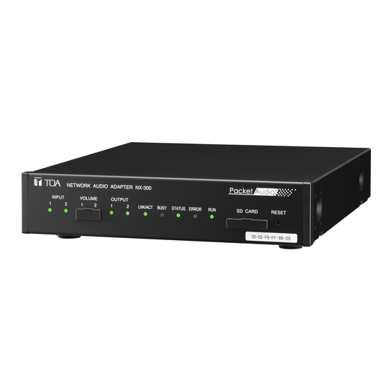
APPENDIX Chapter 6 2. INDICATOR STATUS AND TROUBLESHOOTING NETWORK AUDIO ADAPTER NX-300 INPUT VOLUME OUTPUT LNK/ACT BUSY STATUS ERROR SD CARD RESET 00-05-F9-FF-80-81 Indicator status: Lighting, Flashing, Unlit 1. Input indicator (Green) 4. Busy indicator (Green) Input signal level high enough for network Writing data, updating firmware, etc. - Page 177 AC adapter is disconnected. Ensure the connection of power supply. irm are error firm are runa ay Contact your TOA dealer if detected even after the PC is restarted. Data write error riting data failed because the unit s po er is shut off or other trouble occurs during data rite or firm are update.
- Page 178 APPENDIX Chapter 6 3. LEVEL DIAGRAM 3.1. Block Diagram When used as an input volume control (default setting). MIC (+40 dB*)/ Gain settings Imaginary Volume PAD 16 dB* LINE (+0 dB*) (0/ -10/ amplifier Network Input (- to 0 dB*) -6 dB* ON/OFF Settings...
- Page 179 Use the DIP switch for equipment settings located on the rear panel to perform settings. Use the NX-300 Setting Software to perform settings. Be sure to set the PAD settings to ON when inputting an audio source of this level.
- Page 180 NX-300 unit. network. onfirm that unit s address subnet mas and default gate ay are correctly set. See p.
- Page 181 Other malfunctions When other malfunctions occur, error indicator may light. Since serious failure may have occurred when error indicator lights, check log. See p. peration og to confirm log contents. orgot pass ord. Contact your TOA dealer.
- Page 182 APPENDIX Chapter 6 5. SPECIFICATIONS Power Source upplied from an external po er supply or AC adapter AD-246 (option) or the equivalent o er urrent onsumption operation operation Audio Input channels balanced transformer isolated unbalanced changeable changeable volume ad ustable ated input (MIC) function...
- Page 183 Wall mounting bracket: YC-850 AC adapter: AD-246 Traceability Information for Europe Manufacturer: Authorized representative: TOA Corporation lectronics urope inato ima a amachi huo u yogo uederstrasse amburg Japan Germany http .toa.
Need help?
Do you have a question about the NX-300 and is the answer not in the manual?
Questions and answers