Sign In
Upload
Download
Table of Contents
Contents
Add to my manuals
Delete from my manuals
Share
URL of this page:
HTML Link:
Bookmark this page
Add
Manual will be automatically added to "My Manuals"
Print this page
×
Bookmark added
×
Added to my manuals
Manuals
Brands
Honda Manuals
Inverter
EM10000
Owner's manual
Honda EM10000 Owner's Manual
Hide thumbs
1
2
3
4
Table Of Contents
5
6
7
8
9
10
11
12
13
14
15
16
17
18
19
20
21
22
23
24
25
26
27
28
29
30
31
32
33
34
35
36
37
38
39
40
41
42
43
44
45
46
47
48
49
50
51
52
53
54
55
56
57
58
59
60
61
62
63
64
65
66
67
68
69
70
71
72
73
74
75
76
77
78
79
80
81
82
83
84
85
86
page
of
86
Go
/
86
Contents
Table of Contents
Bookmarks
Table of Contents
Table of Contents
Generator Safety
Important Safety Information
Operator Responsibility
Carbon Monoxide Hazards
Electric Shock Hazards
Fire and Burn Hazards
Refuel with Care
Safety Label Locations
Controls & Features
Component & Control Locations
Controls
Fuel Valve Lever
Choke Knob
Engine Switch
Circuit Breaker
Features
Oil Alert System
I-Monitor
Ground Terminal
Fuel Gauge
Before Operation
Are You Ready to Get Started
Knowledge
Is Your Generator Ready to Go
Check the Engine
Check the Battery
Operation
Safe Operating Precautions
Starting the Engine
Stopping the Engine
Ac Operation
AC Receptacle
AC Receptacle (Three-Phase or Single-Phase) (ET12000 Only)
AC Applications
Standby Power
Connections to a Building's Electrical System
System Ground
Special Requirements
Servicing Your Generator
The Importance of Maintenance
Maintenance Safety
Safety Precautions
Maintenance Schedule
Refueling
Fuel Recommendations
Gasolines Containing Alcohol
Engine Oil Level Check
Engine Oil Change
Engine Oil Recommendations
Air Cleaner Service
Foam Air Filter Cleaning
Sediment Cup Cleaning
Spark Plug Service
Spark Arrester Service
Battery Service
Battery Inspection
Battery Removal
Battery Charging
Battery Installation
Fuse
Storage
Storage Preparation
Cleaning
Fuel
Storage Procedure
Storage Precautions
Removal from Storage
Transporting
Taking Care of Unexpected Problems
Engine Problems
Engine will Not Start
Engine Lacks Power
Generator Problems
No Power at the AC Receptacles
Technical Information
Serial Number Location
Carburetor Modification for High Altitude Operation
Specifications
Wiring Diagram
Optional Parts
Wheel Kit
Hanger Kit
Index
Advertisement
Quick Links
1
Engine Oil Change
2
Specifications
3
Wiring Diagram
Download this manual
11/12/06 12:51:29 42Z26700_001
Honda
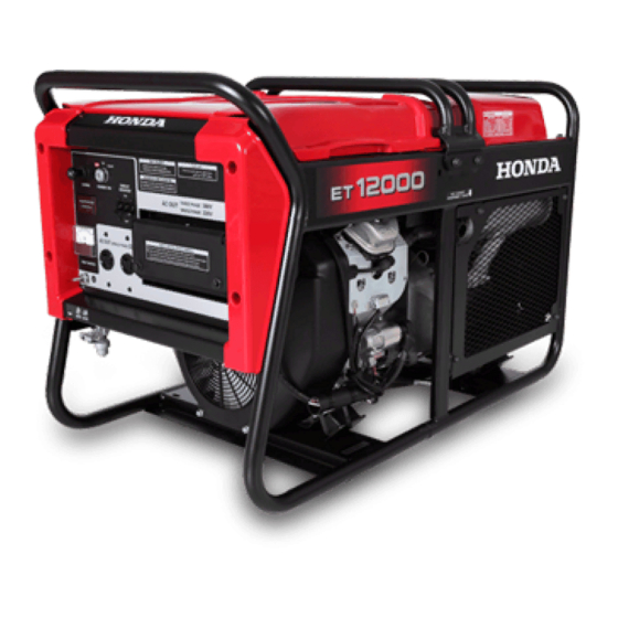
EM10000·ET12000
OWNER'S MANUAL
MANUAL DE EXPLICACIONES
OWNER'S MANUAL
Table of
Contents
Previous
Page
Next
Page
1
2
3
4
5
Advertisement
Table of Contents
Need help?
Do you have a question about the EM10000 and is the answer not in the manual?
Ask a question
Questions and answers
Related Manuals for Honda EM10000
Inverter Honda EM4000SX Owner's Manual
(111 pages)
Inverter Honda EM2300 Owner's Manual
(34 pages)
Inverter Honda E3500 Owner's Manual
Honda generator owner's manual (33 pages)
Inverter Honda EB6500 Owner's Manual
Honda generator owner's manual (52 pages)
Inverter Honda EU2000i Manual
(123 pages)
Inverter Honda EU3000is Owner's Manual
(108 pages)
Inverter Honda EU30is Owner's Manual
(342 pages)
Inverter Honda EU30is Owner's Manual
(17 pages)
Inverter Honda EB10000 Owner's Manual
(111 pages)
Inverter Honda EU10i Owner's Manual
(262 pages)
Inverter Honda EU10i Owner's Manual
(17 pages)
Inverter Honda EU20i Owner's Manual
(238 pages)
Inverter Honda EU 2000i Operation Instructions Manual
2kvh generator (12 pages)
Inverter Honda EC2200 Owner's Manual
Generating set (24 pages)
Inverter Honda EU7000is Job Aid
Mechanical troubleshooting (7 pages)
Inverter Honda EU22i Owner's Manual
(74 pages)
This manual is also suitable for:
Et12000
Table of Contents
Save PDF
Print
Rename the bookmark
Delete bookmark?
Delete from my manuals?
Login
Sign In
OR
Sign in with Facebook
Sign in with Google
Upload manual
Upload from disk
Upload from URL


Need help?
Do you have a question about the EM10000 and is the answer not in the manual?
Questions and answers