Resol DeltaTherm PV Manual For The Specialised Craftsman
Power-to-heat controller for the direct control of an electric heater
Hide thumbs
Also See for DeltaTherm PV:
- Installation, operation, functions and options, troubleshooting (32 pages) ,
- Manual (52 pages)
Table of Contents
Advertisement
Quick Links
DeltaTherm
Power-to-Heat controller
for the direct control of an
electric heater
Manual for the
specialised craftsman
Installation
Operation
Functions and options
Troubleshooting
The Internet portal for easy and secure access to
your system data – www.vbus.net
Thank you for buying this RESOL product.
Please read this manual carefully to get the best performance from this unit. Please keep this manual safe.
PV
®
beginning with firmware version 1.02
en
Manual
www.resol.com
Advertisement
Table of Contents

Related Manuals for Resol DeltaTherm PV


Summary of Contents for Resol DeltaTherm PV
- Page 1 The Internet portal for easy and secure access to your system data – www.vbus.net Manual Thank you for buying this RESOL product. Please read this manual carefully to get the best performance from this unit. Please keep this manual safe. www.resol.com...
- Page 2 Safety advice Target group Please pay attention to the following safety advice in order to avoid danger and These instructions are exclusively addressed to authorised skilled personnel. damage to people and property. Only qualified electricians are allowed to carry out electrical works. Danger of electric shock: Initial commissioning must be effected by authorised skilled personnel.
-
Page 3: Table Of Contents
DeltaTherm ® Single-phase eletromechanical immersion heaters up to 3 kW with an operating The DeltaTherm PV controller detects excess current, e.g. produced by PV ® voltage of 230 V~ and with a thermal cut-out can be used. systems, calculates the energy available and redirects it to an electric heater. Thus, excess current can be directly converted into thermal energy and stored. -
Page 4: Deltatherm ® Pv
DeltaTherm ® Technical data measuring unit (DeltaTherm E sensor) ® • Use of excess current for heating a water store Inputs: 3 current inputs and 3 voltage inputs for SW16 current sensors • Electric heater of up to 3 kW, variable and grid compliant Power supply: 100 –... -
Page 5: System Overview
System overview Energy Sensors Output Controller with power unit meter Temperature store 1 / GND Out1 Electric Out 1 / N / ⏚ immersion optional 2 / GND heater optional 3 / GND Measuring unit VBus ® The control unit consists of the controller with power unit and the measuring unit. The measuring unit measures the current flow directly in front of the energy meter. -
Page 6: Installation
Installation Mounting Dimensions and minimum distances WARNING! Electric shock! Upon opening the housing, live parts are exposed! Î Always disconnect the device from power supply before opening the housing! Note Strong electromagnetic fields can impair the function of the device. Î... - Page 7 105mm 105mm...
-
Page 8: Electrical Connection
Step-by-step installation: Electrical connection ATTENTION! Damage through overheating! WARNING! Electric shock! Commissioning the power stage in a system electrically con- Upon opening the housing, live parts are exposed! nected, but not hydraulically filled can lead to damage caused by Î Always disconnect the device from power supply overheating! before opening the housing! Î... - Page 9 Measuring unit VBus cable to the DeltaTherm PV (VBus 1) ® ® Data communication / VBus ® The connection is to be carried out at the terminals marked VBus (any polarity). The bus cable can be extended by means of a 2-wire cable (bell wire). The cable carries extra-low voltage and must not run together in a cable conduit with cables VBus VBus...
- Page 10 Three-phase connection Single-phase connection Î Connect the current sensor and the conductor L1 of the measuring unit directly Î Connect the current sensors and the conductors of the measuring unit in in front of the energy meter. The arrow indicated on the current sensor must phase directly in front of the energy meter.
- Page 11 Protective earth conductor and shield ⏚ Type label nection is to be carried out at the terminals marked VBus (either polarity). The Basic RESOL art. no.: Art. no.: measuring unit has to be connected to VBus1 (terminals 7 / 8). 0-10 V switching input...
-
Page 12: Microsd Slot Of The Controller
Connection of the electric heater MicroSD slot of the controller Î Connect the immersion heater with a shielded cable with a cross section The controller is equipped with a MicroSD card slot. of 3 x 2,5 mm² and a length of maximum 5 m. With a MicroSD card, the following functions can be carried out: •... -
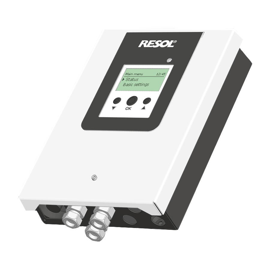
Page 13: Operation And Function Of The Controller
Operation and function of the controller Î To open a submenu or to confirm a value, press the centre button (OK). Î To enter the previous menu, scroll upwards by pressing button or scroll Buttons downwards by pressing button until back is indicated. Î... - Page 14 Adjusting the timer When the Timer option is activated, a timer is in- dicated in which time frames for the function can be adjusted. In the Day selection channel, the days of the week are available individually and as frequently selected combinations.
- Page 15 Copying a time frame: Changing a time frame: In order to copy time frames already adjusted into an- In order to change a time frame, proceed as follows: other day / another combination, proceed as follows: Î Choose the day / the combination into which the time frames are to be copied and select Copy from.
-
Page 16: Commissioning
Resetting the timer: Commissioning In order to reset time frames adjusted for a certain day When the hydraulic system is filled and ready for operation, connect the controller or combination, proceed as follows to the mains. The controller has to be connected to the measuring unit by means of the VBus ®... - Page 17 8. Completing the commissioning menu: Lastly, a security enquiry will appear. If the security en- 1. Language: quiry is confirmed, the adjustments will be saved. Î Adjust the desired menu language. Î In order to confirm the security enquiry, press the centre button (OK).
-
Page 18: Menu Structure
Menu structure Main menu Main menu Status Status Controller Controller Meas. / Balance values Measuring unit Optional functions Messages In this menu, different menu areas can be selected. Basic settings The following menus are available: Controller SD card • Status Maximum temperature Manual mode •... -
Page 19: Controller
4.5.1 Controller When a line with a measurement value is selected, another submenu will open. If, for example, S1 is selected, a submenu indicating the minimum and maximum In the Status / Controller menu, all current controller values (power values, tem- values will open. -
Page 20: Controller Menu
Controller menu Adjustment channel / Adjustment range / Indi- Description Factory setting Indication cation range / Selection Indication of power control Variant 10V IN source Meas. value Signal indication 0.0 … 10.0 V Heat. pow. Heat energy indication 1 … 3000 W Curve Curve submenu Volt 0kW... - Page 21 When a function is selected, a submenu will open in which all adjustments required With the menu item Function, an optional function already saved can be temporarily can be made. deactivated or re-activated respectively. In this case, all adjustments remain stored, the allocated relays remain occupied and cannot be allocated to another function.
-
Page 22: Basic Settings
Adjustment Adjustment range / Description Factory setting channel selection Date Adjustment of the date 01.01.2001 … 31.12.2099 01.01.2017 Time Adjustment of the current time 00:00 … 23:59 Factory setting back to factory setting Yes, No The note also appears, when the booster is active. 4.10 MicroSD card In the status menu, the menu item Booster is available which can be used for heat- ing to Toff outside the time frames. - Page 23 Starting the logging WARNING! Electric shock! Î Adjust the desired logging type and interval. Upon opening the housing, live parts are exposed! Î Always disconnect the device from power supply Logging will start immediately. before opening the housing! Completing the logging process ATTENTION! ESD damage! Î...
-
Page 24: Manual Mode
4.11 Manual mode 4.12 User code Manual mode The access to some adjustment values can be restricted via a user code (customer). 1. Installer 0262 (Factory setting) Adjustment Description Adjustment range / selection Factory setting All menus and adjustment values are shown and all values can be altered. channel If the installer user code is active, an E will be displayed next to the clock time. -
Page 25: Troubleshooting
Troubleshooting The operating control LED flashes red and an error is indicated in the status menu. If a malfunction occurs, a message will appear on the display of the controller (see 4.5.3 on page 19). Is the message !Sensor fault indicated in the Status/Messages menu? WARNING! Electric shock! Upon opening the housing, live parts are exposed! -
Page 26: Index
Operating control LED is permanently red. The display is permanently off. Is the message !VBus Sensor unit indicated in the Status/Messages menu? Press any button. Display illuminated? The error LED of the measuring unit is flashing red? Check the power supply of the controller. Is it Controller has been in disconnected? standby, everything OK... -
Page 27: Accessories
Accessories Index Electric immersion heater Adjusting the timer ......................14 For installation into the store. Balance values ........................19 Commissioning menu ......................16 DL3 Datalogger Controller adjustments, loading of .................. 23 For visualisation via VBus.net, incl. SD card, mains adapter, Controller adjustments, storing of .................. - Page 28 - they only represent use outside the copyright requires the approval of RESOL – Elektronische Rege- some examples. They can only be used at your own risk. No liability is assumed for lungen GmbH.
Need help?
Do you have a question about the DeltaTherm PV and is the answer not in the manual?
Questions and answers