Advertisement
Quick Links
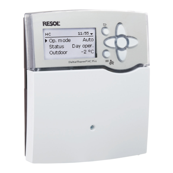
DeltaTherm
Heating controller
Manual for the
specialised craftsman
Installation
Operation
Functions and options
Troubleshooting
The Internet portal for easy and secure access to
your system data – www.vbus.net
Thank you for buying this product.
Please read this manual carefully to get the best performance from this unit.
Please keep this manual safe.
HC Plus
®
beginning with firmware version 1.0
en
Manual
www.resol.com
Advertisement

Related Manuals for Resol DeltaTherm HC Plus


Summary of Contents for Resol DeltaTherm HC Plus
- Page 1 The Internet portal for easy and secure access to your system data – www.vbus.net Thank you for buying this product. Manual Please read this manual carefully to get the best performance from this unit. Please keep this manual safe. www.resol.com...
- Page 2 Safety advice Information about the product Please pay attention to the following safety advice in order to avoid danger and Proper usage damage to people and property. The controller is designed for use in heating systems in compliance with the tech- Danger of electric shock: nical data specified in this manual.
- Page 3 Decommissioning Description of symbols Disconnect the device from the power supply. Warnings are indicated with a warning symbol! Dismount the device. Signal words describe the danger that may occur, when it is not avoided. WARNING means that injury, possibly life-threatening injury, can Disposal occur.
- Page 4 DeltaTherm HC Plus ® The heating controller can control 2 weather-compensated heating circuits and In summer, the heating circuits take over the demand-based cooling by means of a their backup heating demands. humidity sensor for dew point calculation. Additional DHW functions such as circulation or thermal disinfection, and the effi- cient implementation of further heat sources are possible.
- Page 5 Overview Mode of operation: type 1.B.C.Y action Rated impulse voltage: 2.5 kV • 2 mixed heating circuits with backup heating Data interface: VBus ® , SD card slot • Cooling over the heating circuit with humidity sensor VBus current supply: 60 mA ®...
- Page 6 Dimensions and minimum distances Installation 210 mm Mounting 20 mm WARNING! Danger of electric shock! Upon opening the housing, live parts are exposed! Î Always disconnect the device from power supply be- fore opening the housing! Note Strong electromagnetic fields can impair the function of the device. Î...
- Page 7 Chap. 2.2...
- Page 8 Electrical connection Do not use the device if it is visibly damaged! WARNING! Danger of electric shock! The controller is equipped with 7 relays in total to which loads such as pumps, Upon opening the housing, live parts are exposed! valves, etc.
- Page 9 Note The temperature sensors (S1 to S10) have to be connected to the terminals S1 to S10 and GND (either polarity). When Grundfos Direct Sensors are used, connect the sensor ground common terminal block to PE. The cables carry low voltage and must not run together in a cable conduit with cables carrying a voltage higher than 50 V (please pay attention to the valid local Connect the analogue Grundfos Direct Sensors™...
- Page 10 Different solutions for visualisation and remote parameterisation are available on ised, e.g. in a spreadsheet. the website www.resol.com. On the website, firmware updates are also available. • Prepare adjustments and parameterisations on a computer and transfer them via the SD card.
- Page 11 Operation and function Selecting menu points and adjusting values During normal operation of the controller, the display is in the main menu. If no Buttons button is pressed for 1 min, the display illumination switches off. After 3 further The controller is operated via the 7 buttons next to the display. They have the minutes, the controller will display the home screen (see page 37).
- Page 12 adjusted value (not yet Adjustment confirmed) channel If only one item of several can be selected, they will be indicated with radio buttons. When one item has been selected, the radio button in front of it is filled. current value saved minimum value maximum value Values and options can be changed in different ways:...
- Page 13 Adjusting the timer When the Timer option is activated, a timer is in- dicated in which time frames for the function can be adjusted. In the Day selection channel, the days of the week are available individually and as frequently selected combinations.
- Page 14 Copying a time frame: Changing a time frame: In order to copy time frames already adjusted into an- In order to change a time frame, proceed as follows: other day / another combination, proceed as follows: Choose the day / the combination into which the time frames are to be copied and select Copy from.
- Page 15 Resetting the timer: Adjusting functions In order to reset time frames adjusted for a certain day or combination, proceed as follows: Select the desired day or combination. In the Optional functions / Add new function menus, optional functions can be selected and adjusted.
- Page 16 If Switch is selected, the channel Sensor appears, in which a sensor input can be defined as a switch. At the end of each optional function submenu, the menu items Funct. and Save function are available. In order to save a function, select Save function and con- firm the security enquiry by selecting Yes.
- Page 17 Output submenu All controller and module (if connected) outputs available will be displayed. If - is se- The Output submenu is available in almost all functions. Therefore, it will not be explained in the individual function descriptions. lected, the function will run normally in the software but will not operate an output. Relay and signal outputs can be activated separately.
- Page 18 In the Speed adjustment channel, the speed control for the output can be activat- ed or deactivated respectively. If Yes is selected, the channels Min. and Max. will appear. In the Min. adjustment channel, a relative minimum speed for a pump connected can be allocated to the output In the Max.
- Page 19 PWM/0-10 V option Manual mode If the PWM/0-10 V option is activated, a PWM/0-10 V output can be allocated to In the Manual mode adjustment channel, the operating mode of the output can be the output selection. selected. The following options are available: In the Signal channel, a selection between a PWM or a 0-10 V signal can be made.
- Page 20 Commissioning 1. Language: Î Adjust the desired menu language. When the hydraulic system is filled and ready for operation, connect the controller to the mains. The controller runs an initialisation phase in which the directional pad glows red. When the controller is commissioned or when it is reset, it will run a commis- sioning menu after the initialisation phase.
- Page 21 7. Completing the commissioning menu: After the system has been selected or the scheme number has been entered, a security enquiry appears. If the security enquiry is confirmed, the adjustments will be saved. Î In order to confirm the security enquiry, select Yes.
- Page 22 Schemes with basic settings The controller is pre-programmed for 11 basic systems. The basic pre-adjust- ments have already been made. For backup heating it is necessary to allocate the demand and the boiler loading pump by means of shared relays. Afterwards the system can easily be extended.
- Page 23 Scheme 1: 1 mixed heating circuit Sensors Temperature sensors Relay outputs Outdoor S1 / GND Flow HC1 S2 / GND Free S3 / GND Free S4 / GND Free S5 / GND Free S6 / GND Free S7 / GND Free S8 / GND Free...
- Page 24 Scheme 2: 1 mixed heating circuit with backup heating (demand) Sensors Temperature sensors Relay outputs Outdoor S1 / GND Flow HC1 S2 / GND Free S3 / GND Backup heating/ boiler S4 / GND Free S5 / GND Free S6 / GND Free S7 / GND Free...
- Page 25 Scheme 3: 1 mixed heating circuit with backup heating (demand and boiler loading pump) Sensors Temperature sensors Relay outputs Outdoor S1 / GND Flow HC1 S2 / GND Free S3 / GND Backup heating/ boiler S4 / GND Free S5 / GND Free S6 / GND Free...
- Page 26 Scheme 4: 1 mixed heating circuit with DHW heating Sensors Temperature sensors Relay outputs Outdoor S1 / GND Flow HC1 S2 / GND S3 / GND Free S4 / GND Free S5 / GND Free S6 / GND Free S7 / GND Free S8 / GND Free...
- Page 27 Scheme 5: 1 mixed heating circuit with DHW heating and backup heat- ing (demand for heating circuit and DHW) Temperature sensors Relay outputs Sensors Outdoor S1 / GND Flow HC1 S2 / GND S3 / GND Backup heating/ boiler S4 / GND Free S5 / GND Free...
- Page 28 Scheme 6: 1 mixed and 1 unmixed heating circuit Sensors Temperature sensors Relay outputs Outdoor S1 / GND Flow HC1 S2 / GND Flow HC2 S3 / GND Free S4 / GND Free S5 / GND Free S6 / GND Free S7 / GND Free...
- Page 29 Scheme 7: 1 mixed and 1 unmixed heating circuit with backup heating (demand) Temperature sensors Sensors Relay outputs Outdoor S1 / GND Flow HC1 S2 / GND Flow HC2 S3 / GND Backup heating/ boiler S4 / GND Free S5 / GND Free S6 / GND Free...
- Page 30 Scheme 8: 1 mixed heating circuit with solid fuel boiler Sensors Relay outputs Temperature sensors Outdoor S1 / GND Flow HC1 S2 / GND Solid fuel boiler S3 / GND Free S4 / GND Store S5 / GND Free S6 / GND Free S7 / GND Free...
- Page 31 Scheme 9: 1 mixed heating circuit with solid fuel boiler and backup heating (demand) Sensors Temperature sensors Relay outputs Outdoor S1 / GND Flow HC1 S2 / GND Solid fuel boiler S3 / GND Backup heating/ boiler S4 / GND Store S5 / GND Free...
- Page 32 Scheme 21: 2 mixed heating circuits Sensors Temperature sensors Relay outputs Outdoor S1 / GND Flow HC1 S2 / GND Flow HC2 S3 / GND Free S4 / GND Free S5 / GND Free S6 / GND Free S7 / GND Free S8 / GND Free...
- Page 33 Scheme 22: 2 mixed heating circuits with backup heating (demand) Sensors Temperature sensors Relay outputs Outdoor S1 / GND Flow HC1 S2 / GND Flow HC2 S3 / GND Backup heating/ boiler S4 / GND Free S5 / GND Free S6 / GND Free S7 / GND...
- Page 34 Step-by-step parameterisation 4. Adjusting the operating mode After commissioning the heating circuit will be in automatic mode. The operating The heating controller DeltaTherm HC Plus is a controller that offers a broad ® mode can be changed in the status menu (see page 15). variety of functions to the user.
- Page 35 Menu structure Main menu Status Heating Heating Arrangement Shared rel. Heating circuit Basic settings Basic settings Basic settings Opt. functions Heat. sys. System SD card Screed drying Cooling system HC pump Manual mode Room control Mixer op. User code Special funct. Mixer cl.
- Page 36 Main menu Status In the status menu of the controller, the status messages for every menu area can be found. At the end of each submenu, the menu item Adj. values can be found. If this one is selected, the corresponding menu opens. Î...
- Page 37 Arrangement When the installer user code has been entered, the menu item Restarts will ap- pear below the messages. The value indicates the number of controller restarts This menu shows all status information of all activated optional functions of the since commissioning.
- Page 38 Heating Heating / Shared rel. Adjustment Adjustment range / In this menu, all adjustments for the heating part of the arrangement or for the Description Factory setting channel selection heating circuits respectively can be made. Dem. 1 (2) Demand 1 (2) Activated, Deactivated Deactivated Shared relays for demands, loading pumps or valves can be activated, heating circuits Dem.
- Page 39 The Boiler pr. max option is used for protecting a boiler against overheating. If the Adjustment Adjustment range / Description Factory setting adjusted maximum temperature is exceeded, the allocated relay will be switched off channel selection until the temperature falls by 5 K below the maximum temperature. Min.
- Page 40 voltage signal accordingly. In order to do so, the controller checks the temperature If new HC… is selected for the first time, the first heating circuit is allocated to at the boiler flow sensor when the interval has elapsed. If the temperature meas- the controller.
- Page 41 By means of the adjustment channels TFlowmax and TFlowmin the maximum Adjustment Adjustment range / Description Factory setting and minimum values for the set flow temperature can be defined. channel selection Output selection mixer system depend- Mixer cl. system dependent If the outdoor temperature sensor is defective, an error message will be indicated.
- Page 42 The parameter Mode is used for selecting between the following correction modes: In the Room influence mode, the weather-compensated set flow temperature Day/Night: A reduced set flow temperature (night correction) is used during will be expanded by a demand-based room control. The parameter Room factor Night operation.
- Page 43 Adjustment Adjustment range / Description Factory setting channel selection Curve Heating curve 0.3 … 3.0 Room factor Room influence factor 1 … 9 TFlowset Set flow temperature 10 … 90 °C 45 °C TOutdoor 1 Lower outdoor temperature -20 … +20 °C +20 °C TFlow 1 Lower set flow temperature 20 …...
- Page 44 In the both mode, both switching conditions are valid for cooling. Adjustment Adjustment range / Description Factory setting If the Timer option is activated, a time frame can be adjusted in which the cooling channel selection will be active. Boiler loading pump output system depend- Loading pump system dependent...
- Page 45 Zone: In this mode, the set flow temperature is compared to 2 store reference Adjustment Adjustment range / Description Factory setting sensors. The switching conditions have to be fulfilled at both reference sensors. channel selection On/Off: In this mode, the backup cooling is activated when the heating circuit system depend- Output Output selection...
- Page 46 8.2.4 Room control submenu Adjustment Adjustment range / Description Factory setting channel selection system depend- Sen. Room Room sensor allocation system dependent TAmb.set Set room temperature 10 … 30 °C 18 °C Hysteresis Hysteresis 0.5 … 20.0 K 0.5 K Timer Timer function Yes, No...
- Page 47 The remote control allows manual adjustment of the heating curve (± 15 K). Fur- In the chimney sweeper mode, the heating circuit mixer opens, the heating circuit thermore, the heating circuit can be switched off or a rapid heat-up can be carried pump and the backup heating contact are activated.
- Page 48 Energy saving operation Adjustment Adjustment range / Description Factory setting channel selection TFlowset Set flow temperature antifreeze 20 … 50 °C 20 °C Heat dump Heat dump option Yes, No system depend- Sensor Allocation heat dump sensor system dependent Switch-on temperature heat dump 25 … 95 °C 85 °C TOff Switch-off temperature heat dump 20 …...
- Page 49 Note With the TD holid. off option, thermal disinfection can be deactivated for a phase of absence. For further information about adjusting optional functions, see page 15. Î In order to adjust the days of absence, press and hold down button ➆ for 5 s. Note With the BAS off option, the thermal disinfection can be switched from automatic For information on the output selection see page 17.
- Page 50 DHW heating With the BAS off option, DHW heating can be switched from automatic mode to Off by means of the operating mode switch. If SFB off is activated, DHW heating is suppressed when a selected solid fuel boiler is active. Heating / Opt.
- Page 51 DHW preheating Heating / Opt. functions / Add new function / DHW preheat. Adjustment Adjustment range / Description Factory setting channel selection Pump Output selection pump system dependent Valve Valve option Yes, No Valve Output selection valve system dependent Temp. sensor Temperature sensor system dependent Sen.
- Page 52 Circulation Demand The allocated flow switch is monitored for circuit continuity. If circuit continuity is detected at the flow switch, the output switches on for the adjusted runtime. After the runtime has ended, the output switches off. During the adjusted break time, the output remains switched off even if continuity is detected at the allocated sensor.
- Page 53 Screed drying If the set flow temperature is not reached within 24 hours or after the rise time respectively, or if it is constantly exceeded, the screed drying function will be can- celled. The heating circuit switches off and an error message is displayed. The directional pad glows red.
- Page 54 Set flow temperature Arrangement tBacking TMax Rise time Rise TStart In this menu, all adjustments for the non-heating part of the arrangement can be made. Days Up to 16 optional functions can be selected and adjusted. The diagram shows the parameters of the screed drying with the factory settings. Optional functions Heating / Screed drying Adjustment...
- Page 55 If the Delay option is activated, the output is energised after the adjusted duration Adjustment Description Adjustment range / selection Factory setting has elapsed. If the reference relay is switched off again during the delay time, the channel parallel output is not be switched on at all. system depend- Sensor Sensor selection...
- Page 56 Heat exchange Adjustment range / Adjustment channel Description Factory setting selection Activated, Deactivated, Funct. Activation / Deactivation Activated Switch Sensor Switch input selection Error relay Sensor Source This function can be used for operating an output in case of an error. Thus, e.g. a signalling device can be connected in order to signal errors.
- Page 57 Arrangement / Opt. functions / Add new function / Heat exchange This function can be used for transferring heat from a solid fuel boiler to a store. The allocated output is energised when all switch-on conditions are fulfilled: Adjustment Adjustment range / Description Factory setting •...
- Page 58 The allocated output is energised when all switch-on conditions are fulfilled: Adjustment Adjustment range / Description Factory setting channel selection • the temperature difference between the allocated sensors has exceeded the system depend- switch-on temperature difference Mixer op. Output selection mixer open system dependent •...
- Page 59 Function block OR mode If at least one of the reference outputs is switched on, the switching condition for the reference output function is considered fulfilled. If none of the reference outputs is switched on, the switching condition for the reference output function is considered unfulfilled.
- Page 60 Adjustment Adjustment range / Description Factory setting Reference channel selection output Fl.rate Tha- S3* Thb-S4* ΔT-S3>S4* Timer system depend- Sensor Sensor thermostat b system dependent Function Thermostat a ΔT function Differential function Yes, No Thermostat b Switch-on temperature difference 1.0 … 50.0 K 5.0 K ΔTOn ΔT function...
- Page 61 Return mixing function Heating circuit Internal If Internal is selected in the HC parameter, the return mixing function will only become active when the selected heating circuit of the controller is active, too. For this purpose, the heating circuit selected has to be controlled by the controller or by a module connected.
- Page 62 Flow rate monitoring This function can be used to detect malfunctions that impede the flow rate and to In this menu, up to 7 calorimeters can be activated and adjusted, thereof 1 impulse switch off the corresponding output. This will prevent system damage, e.g. through counter.
- Page 63 If a calorimeter is being configured for the first time or after the overall quantity has Impulse counter been reset, the parameter Carryover appears. A former value which is to be added to the overall quantity can be entered. When the Alternative unit is activated, the controller converts the heat quantity into the quantity of fossil fuels (coal, oil or gas) saved, or the CO emission saved respectively.
- Page 64 Basic settings 11.1 Sensors In this submenu, the type of the sensor connected can be adjusted for each individ- In this menu, all basic parameters for the controller can be adjusted. Normally, these settings ual input. The following types can be selected: have been made during commissioning.
- Page 65 Basic settings / Sensors 11.2 Modules Adjustment Adjustment range / Description Factory setting channel selection S1 … S10 Sensor input selection Switch, Fern (remote con- trol), BAS (operating mode Type Sensor type selection Pt1000 switch), Pt1000, Pt500, KTY, None Offset Sensor offset -15.0 …...
- Page 66 While the adjustments are being stored, first Please wait…, then Done! will be indicated on the display. The controller adjustments are stored as a .SET file on the The current software can be downloaded from www.resol.com/firmware. When SD card. an SD card with a firmware update is inserted, the enquiry Update? is indicated on the display.
- Page 67 Manual mode Manual mode Adjustment Adjustment range / Description Factory setting channel selection Selection operating mode of All outputs... Auto, Off all relays Relay 1 … X Operating mode of relay On, Auto, Off Auto Operating mode of signal Output A … B On, Max., Auto, Min., Off Auto output Demand 1 (2)
- Page 68 The fuse of the controller could be Check the supply line and recon- nect it. blown. The fuse holder (which holds the spare fuse) becomes accessible when the cover is removed.The fuse can then be replaced. Note For answers to frequently asked questions (FAQ) see www.resol.com.
- Page 69 Stores cool down at night. The heating circuit pump does not work, although this is indicated on the status display. Sufficient store insulation? Display illuminated? Increase insulation. If not, press button ➄. Display Insulation close enough to the store? illuminated again? Replace insulation or increase it.
- Page 70 Index Numbers 0-10 V boiler control ......................39 Heating circuit mixer ......................40 Heating circuit pump ......................40 Heating curve ........................41 Antifreeze function ......................47 HE pump ..........................9 App ............................47 Holiday ........................... 36 Automatic mode ......................... 34 Interval...........................
- Page 71 Screed drying ........................53 Set flow temperature ......................41 Shared relays ........................38 Solid fuel boiler ........................57 Starting temperature ......................53 Storing controller adjustments ..................66 Technical data ......................... 5 Thermal disinfection ......................49 Thermostat function ......................59 Timer ............................. 13 VBus .............................
- Page 72 The texts and drawings in this manual are correct to the best of our knowledge. As faults can never be excluded, please note: outside the copyright requires the approval of RESOL – Elektronische Regelun- gen GmbH. This especially applies for copies, translations, micro films and the stor- Your own calculations and plans, under consideration of the current standards and age into electronic systems.
Need help?
Do you have a question about the DeltaTherm HC Plus and is the answer not in the manual?
Questions and answers