Table of Contents
Advertisement
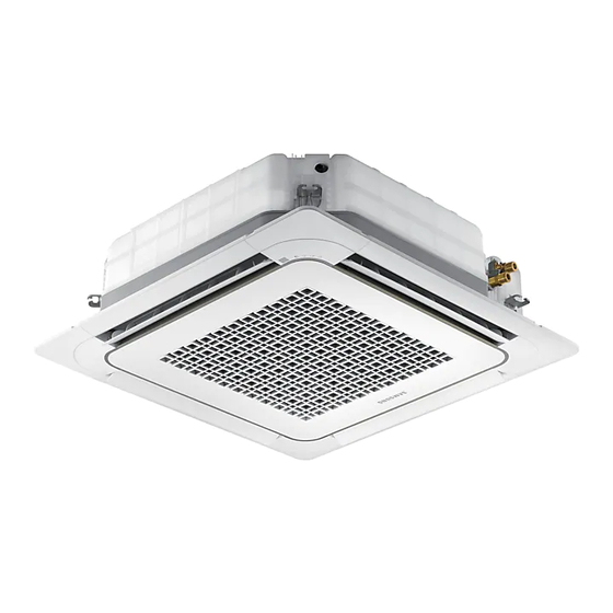
Fan Coil Unit
System Airconditoner
Fan Coil Unit
AG026/32MN1DEH/EU
AG042MN1DEH/EU
AG060/072/090/105MN4DKH/EU
AG060/072/090/105MN4PKH/EU
Contents
1. Precautions
2. Product Specifications
3. Disassembly and Reassembly
4. Troubleshooting
5. PCB Diagram and Parts List
6. Wiring Diagram
7. Reference Sheet
Advertisement
Table of Contents


Need help?
Do you have a question about the AG026MN1DEH/EU and is the answer not in the manual?
Questions and answers