Table of Contents
Advertisement
Quick Links
INSTALLER'S PARAMETERS
To access to the installation parameters menu, press
Use
and
keys to show the parameter to adjust.
Press
to toggle the parameter setting or edit the value. If the value starts to blink you can use
keys to adjust this value. Press
and
keys at the same time to reset this value to the factory default value.
Once you have adjusted the value press
to validate this parameter value.
When you have finished, go to « CrF Init » parameter and press
Installation parameters:
name
Description
CrF Init
Use this parameter to configure the thermostat with the receiver.
J0
°C or °F temperature display selection
J1
12h or 24h time display
CH
Numbers of zones installed on your installation
Type of installation:
Menu: The cold warm change is manually
managed by the end user. (On the thermostat)
H.C
Auto: The cold warm change is managed by the
automatic reversible Heat pump. (Special input on
the RF Receiver)
or
Select Hot
CoLd to adjust :
J2
if lit up =>
adjust the heater parameters.
if lit up =>
adjust the cooler parameters.
Anti-lock-braking function of the pump
When the pump hasn't worked on a particular day,
J5
start it up for one minute each day.
(adjustable in
&
in Menu position
Air or Floor temperature regulation selection.
J6
(if no Floor sensor, regulation will use Air sensor)
Selection of regulation type
J7
(adjustable in
&
in Menu position
Selection of the proportional band duration in
minutes
Cy
(adjustable in
&
in Menu position
Minimal starting time in minutes
On
(adjustable in
&
in Menu position
Minimal resting time between 2 heating cycles in
minutes
OF
(adjustable in
&
in Menu position
Value of the proportional band (PWM)
bP
(adjustable in
&
in Menu position
Air sensor offset adjustment.
Ao
Display measured Air sensor value.
Floor sensor offset adjustment.
Fo
Display measured Floor sensor value.
Floor temperature LOW limitation,
Effective only if floor sensor present.
FL
(adjustable in
&
in Menu position
Floor temperature HIGH limitation,
Effective only if floor sensor present.
FH
(adjustable in
&
in Menu position
GAP
Value of the dead zones (only for "Mod Auto")
Time delay between the Heat and Cold
dLY
commutation in minutes (only for "Mod Auto")
CLr
Press
during 5sec to reset your thermostat, all parameter will reload with default values.
during 10 s.
to go back to the main menu.
Default setting
Other possibility
°C
°F
24h
12h
12
Adjustable « 01 » to « 12 »
Menu
Auto
Hot
CoLd
Yes
no
)
Air
FLor
Bp
« hyst »
(PWM)
static differential of 0.5°C
)
Heating application :
15 =>
Burner oil « 20 »
Slow system
Burner gas « 10 »
adapted to each
Actuator « 10 »
heating type
Heat pump « 20»
Cooling application :
30 =>
Heat pump/ Air conditioning « 30»
)
adapted to Heat
Ventilate convector « 10 »
pump control
2 =>
Adjustable, 0 to ½ Cy
)
4 =>
3 =>
Adjustable, 0 to ½ Cy
4 =>
)
Adjustable 1°C to 6°C
A well insulated house 1.5°C
2.0°C =>
In case of your house has not a
)
4.0°C =>
good insulation increase this value.
No offset
Adjustable +/ – 12°C
No offset
Adjustable +/ – 12°C
18°C =>
Adjustable 5,0 °C to
)
18°C =>
28°C =>
FL
Adjustable
)
37°C =>
4,0°C
Adjustable 0,2°C to 25 °C
60
Adjustable 1 to 240 min
USER GUIDE
HUMIDITY THERMOSTAT & ZONES PROGRAMMER
and
TECHNICAL CHARACTERISTICS
Measuring accuracy
Operating temperature
Ambient temperature range
Regulation characteristics
Electrical Protection
Feeding and autonomy
Radio frequency and
certifications
External probe in option
Program version
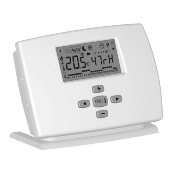
DISPLAY
OPERATING MODE DESCRIPTION
FH
Use
and
keys to change operating mode.
to 37°C
Humidity Mode:
Use
and
to set the maximum humidity value (in relative humidity percent) of your room.
The humidity drier output will be switch on when the current humidity is above this value.
This output is controlled only in cooling mode "Mod COOL " or 'Mod AUTO" in cooling.
o
Weekly and 12 zones programmer.
o
Permanent memory storage
o
Regulation by internal or external probe in option.
o
Heating, Cooling and humidity control.
0.1°C
0°C - 50°C
5° C – 37° C in steps of 0.5° C
Integral proportional band (PWM) or Static differential.
Class II - IP30
3 batteries AA LR06 1.5 V / > 2 years (alkaline batteries)
433,92MHz, < 10mW
CE. EN 300220-1, EN 301489-1
CTN 10K 3M
To display the software version press the
during 3sec in anti freeze
mode
. "Crf _.__"
1:
Function mode.
2:
Heating mode indicator.
3:
Cooling mode indicator.
4:
Ambient temperature indicator.
5:
Ambient temperature if "4" lit up, current zone or
temperature required.
6:
Weekly program / Radio frame.
7:
Humidity level or time.
8:
Current day of the week.
9:
Low batteries.
10:
GB
PPL IMP 1305 A
Advertisement
Table of Contents

Related Manuals for Watts MILUX-HY


Summary of Contents for Watts MILUX-HY
-
Page 1: User Guide
INSTALLER’S PARAMETERS USER GUIDE HUMIDITY THERMOSTAT & ZONES PROGRAMMER To access to the installation parameters menu, press during 10 s. keys to show the parameter to adjust. Press to toggle the parameter setting or edit the value. If the value starts to blink you can use keys to adjust this value. - Page 2 PROGRAM EDITION Comfort Mode: Use this mode to set your installation indefinitely in Comfort mode. The room temperature and the humidity level are displayed all the time. If you press you can see the setting By pressing key the zone number starts to blink, temperature and actual time.
- Page 3 Installation Installation Installation Installazione Instalación instalação installatie Asennus Installation Installasjon 60mm < 125mm 34mm PPL IMP 1300A...
Need help?
Do you have a question about the MILUX-HY and is the answer not in the manual?
Questions and answers