Table of Contents
Advertisement
Quick Links
- 1 Installation Considerations
- 2 Unpacking Zone Sensor and Determining Best Location
- 3 Connecting Zone Sensor Wiring
- 4 Setup Guide
- 5 Apply Power and Set Zone Numbers
- 6 Menu > Advanced Settings
- 7 Thermostat Initial Commissioning
- 8 Icomfort S30 Ultra Smart Thermostat - Installer Zoning Control Settings
- Download this manual
Advertisement
Table of Contents

Related Manuals for Lennox iHarmony Zone Thermostat


Summary of Contents for Lennox iHarmony Zone Thermostat
- Page 1 Zoning System - Zone Sensor ® (17A30) 507826-02 11/2019 Supersedes 507826-01 Lennox Industries Inc. Installation and Setup Guide © Dallas, Texas, USA...
-
Page 2: Table Of Contents
Installer Checklist ............ 14 Summary of Changes ..........15 The 17A30 Zone Sensor can be used in systems controlled by any Lennox communicating thermostat. The 17A30 zone sensor can also be used in combination with the now discontinued 10C17 In-... -
Page 3: Electrical Characteristics
Dimensions CAUTION This is a 12VDC low-voltage zone sensor. Do not Unit Dimensions (H x W x D) install on voltages higher than 14VDC. Dimensions: 3-5/16 x 4-5/16 x 7/8 in. (84 x 110 x 22mm) Electrical Characteristics Wall Plate Dimensions (H x W) All values are at 77°F (25°C). -
Page 4: Unpacking Zone Sensor And Determining Best Location
Unpacking Zone Sensor and Determining Installing Zone Sensor Best Location This procedure is for either new or relocating a zone IMPORTANT sensor installations. 1. Unpack the zone sensor. Installation uses 18 gauge thermostat wire with a wire run length NOT TO EXCEED 197 feet (60 2. - Page 5 5. Trim 1/4 inch (6 mm) insulation from end of each 8. Remove back plate from main zone sensor thermostat wire lead. assembly using a flat-head screw driver. 6. Use the provided wall plate as a template on where to drill the mounting holes. NOTE: Installation of wall plate is optional.
-
Page 6: Zone Sensor Terminal Information
10. Secure back plate and wall plate (optional) to Connecting Zone Sensor Wiring wall with the two provided mounting screws. Use “Table 2. Terminal Designations” on page 6 for connecting the thermostat wiring to the back plate terminals. Wall Plate (optional) Zone Sensor Back Plate Screw Zone Sensor Terminal Information... -
Page 7: Install Zone Sensor To Backplate
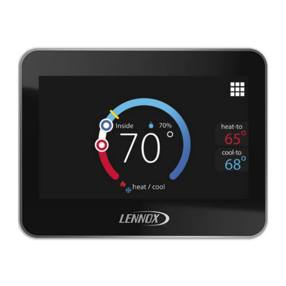
If power is applied and the zone sensor screen remains off, inspect and verify all wire connections. After power is applied to the zone sensor for the first time it will display the Lennox “splash screen” ® and then the zone number selection screen. Set the... -
Page 8: Menu > Advanced Settings
address using the plus/minus buttons. Selections Table 3. Advanced Settings are 2, 3 or 4. Menu Selection Setting NOTE: Zone 1 is always the S30 thermostat. Each Resets the zone sensor to factory additional zone sensor will have to have a Reset default settings. -
Page 9: Icomfort S30 Ultra Smart Thermostat - Installer Zoning Control Settings
Rerunning Thermostat Commissioning iComfort S30 Ultra Smart Thermostat - Installer Zoning If zoning control was added to an existing S30 Control Settings control system. Perform the following steps: 1. From the home screen, select the Menu Icon Thermostat Initial Commissioning 2. -
Page 10: Verify Airflow Per Zone
Changing Zone Names NOTE: If a particular zone is missing from the list, verify that the zone sensor wiring is correct and that the zone number address is set If at a later time the zone name needs to be changed, correctly on both types of zone sensors use the following procedure to do so: (17A30 and 10C17). - Page 11 Alert Codes Table 4. Alert Codes Condition and Error Message Thermostat Display Action to Clear / Email Notification System Action Code Type Text Recovery Condition Description Indoor temp is displayed as “--” on the home screen. Two dashes will be displayed inside on the S30 thermostat and/or...
- Page 12 Table 4. Alert Codes Condition and Error Message Thermostat Display Action to Clear / Email Notification System Action Code Type Text Recovery Condition Description Temperature Sensor Problem (Zoning Error Control) Temperature Sensor Problem (Zoning If problem is due to Error Control) System will go into temperature sensor issue,...
- Page 13 Table 4. Alert Codes Condition and Error Message Thermostat Display Action to Clear / Email Notification System Action Code Type Text Recovery Condition Description A pop-up display will appear indicating communication Once communication is error. reestablished the device Indoor temp is will return to normal zone displayed as “--”...
-
Page 14: Installer Checklist
Installer Checklist Table 5. Installation Checklist Item Description Is the zone sensor properly mounted to either a wall stud or wall? (Do not mount on exterior wall or near any ventilation outputs, doorways or location that could be directly exposed to sunlight) Are all terminals wiring properly connected and tight? Have all the zone sensor features been explained to the homeowner? Has user manual been given to homeowner? -
Page 15: Summary Of Changes
Summary of Changes 11/2019 - Updated instruction to include more detail and clarification concerning zone sensor ID assignment and recommission of the S30 thermostat.
Need help?
Do you have a question about the iHarmony Zone Thermostat and is the answer not in the manual?
Questions and answers