Table of Contents
Advertisement
Quick Links
E2013 Lennox Industries Inc.
Dallas, Texas, USA
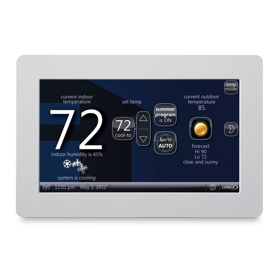
indoor temperature
indoor humidity is 41%
system is cooling
Wi-Fi
9:39 am Aug 15, 2012
NOTICE
Read this manual before programming this thermostat.
Use this thermostat only as described in this manual.
icomfortt-Enabled Units
Indoor Unit
G71MPP-03 or later
SLP98-01 or later
SL280-03 or later
EL296V-01 or later
CBX40UHV-02 or later
CBX32MV-06 or later
Shipping and Packing List
®
1 - iComfort Wi-Fi
thermostat
4 - Mounting Screws
4 - Wall Anchors
1 - Installation Quick Start Guide
1 - Installer's System Setup Guide
1 - Homeowner's Manual
1 - Warranty card
CAUTION
Electric shock hazard.
Always turn off power at the main power source by switching
the circuit breaker to the OFF position before installing or re
moving this thermostat.
All wiring must conform to local and national building and
electrical codes and ordinances.
7/2013
*2P72013*
outdoor
temperature
set temp
enter
80
away
heat
75
or
cool
cool-to
72
fan is
fan is
fan is
AUTO
heat to
AUTO
OFF
Outdoor Units
XC17-02 or later
XP17-02 or later
XP17N-01 or later
XP19-06 or later
XC21-05 or later
XP21-01 or later
XP21N-01 or later
XP25-01 or later
XC25-01 or later
INSTALLER'S SYSTEM
SETUP GUIDE
iComfort Wi-Fi
Touch Screen Programmable Communicating Thermostat
CONTROLS
507152-01
7/2013
Supersedes 5/2013
. . . . . . . . . . . . . . . . . . . . . . . . . . . . . . . . . . . . .
. . . . . . . . . . . . . . . . . . . . . . . . . . . . . . . . . .
. . . . . . . . . . . . . . . . . . . . . . . . . . . . . . . .
. . . . . . . . . . . . . . . . . . . . . . . . . . . . . . . . . . . . . .
®
. . . . . . . . . . . . . . . . . . . . . . . . . . . . . . . . .
. . . . . . . . . . . . . . . . . . . . . . . . . . . . . . . . . . . . . . . . . . . .
. . . . . . . . . . . . . . . . . . . . . . . . . . . . . . . . . . . .
. . . . . . . . . . . . . . . . . . . . . . . . . . . . . . . . . . . . . . . . .
. . . . . . . . . . . . . . . . . . . . . . . . . . . . . . . . .
. . . . . . . . . . . . . . . . . . . . . . . . . . . . . . . . . . . . . . . . . .
. . . . . . . . . . . . . . . . . . . . . . . . . . . . . . . . . . . . .
. . . . . . . . . . . . . . . . . . . . . . . . . . . . . . . . . . . . . . . . . . . . . . . . . . .
WARNING
Improper installation, adjustment, alteration, service or maintenance can
cause property damage, personal injury or loss of life.
Installation and service must be performed by a licensed professional HVAC
installer (or equivalent) or service agency.
CAUTION
This is a 24VAC Class 2 thermostat. Do not install on voltages higher than
30VAC.
Do not switch system to cool if the outdoor temperature is below 45°F (7°C).
This can damage the cooling system.
*P507152-01*
®
Thermostat
. . . . . .
. . . . . . . . . . . . . . . . . . . . . . .
. . . . . . . . . . . . . . . . . . . . . . . . . . . . . . .
. . . . . . . . . . . . . . . . . . . . . . . . . . . .
. . . . . . . . . . . . . . . . . . . . . . . . . .
. . . . . . . . . . . . . . . . . . . . . . . . . . . . . .
. . . . . . . . . . . . . . . . . . . . . . . . . . . .
. . . . . . . . . . . . . . . . . . . . . . .
. . . . . . . . . . . . . . . . . . . . . . . .
. . . . . . . . . . . . . . . . . . . . . . . . . . . . .
. . . . . . . . .
. . . . . . . . . . . . . . . . . . . . . . . . . . .
. . . . . . . . . . . . . . . . . . . . . . . . .
. . . . . . . . . . . . . . . . . . . . . . . . . .
. . . . . . . . . . . . . . . . . . .
. . . . . . . . . . . . . . . . . . . . . . . .
. . . . . . . . . . . . . . . . . . . . . . . . . . .
. . . . . . . . .
. . . . . . .
. . . . . . . . . .
. . . . . . . . . . . . . . . . . . . . . . . . . . .
. . . . . . . . . . . . . . . . . . . .
507152-01
Litho U.S.A.
2
2
2
4
4
4
5
5
6
11
13
15
17
18
19
20
20
21
22
22
.
22
24
25
35
38
39
39
39
40
40
41
41
41
42
42
43
Advertisement
Table of Contents

Subscribe to Our Youtube Channel
Related Manuals for Lennox iComfort G71MPP-03


Summary of Contents for Lennox iComfort G71MPP-03
-
Page 1: Table Of Contents
INSTALLER'S SYSTEM SETUP GUIDE E2013 Lennox Industries Inc. ® iComfort Wi-Fi Thermostat Dallas, Texas, USA Touch Screen Programmable Communicating Thermostat CONTROLS 507152-01 Litho U.S.A. outdoor 7/2013 indoor temperature temperature set temp enter Supersedes 5/2013 away heat Icomfort Wi-FI™ Thermostat - Technical Description and Features... -
Page 2: Icomfort Wi-Fi™ Thermostat - Technical Description And Features
January 2012 and De-humidification without user involvement OUTDOOR TEMPERATURE SENSOR 09 : 39 am All Lennox branded communicating outdoor units contain a built-in outdoor temperature sensor. INSTALLATION AND SETUP COMMUNICATION ERROR SCREEN During initial thermostat start-up if the following screen appears (see figure 1), this save will indicate that the thermostat has been incorrectly wired or has shorted wires. - Page 3 The dealer number is your Lennox account number. Enter the entire 2. Enter the Dealer Number using the on-screen keyboard (see figure 4). Press dealer number including the letters and numbers (.e. A12345). If you save to continue.
-
Page 4: Identifying System Devices
IDENTIFYING SYSTEM DEVICES From the “system devices” screen, use arrow buttons to scroll to a device; then press the about button. Use the up/down arrows to scroll through and view additional information about the selected device. When finished viewing, press the back button. device feature list Language Support system devices... -
Page 5: Bypass (24Vac) Humidifier
ADDING A HUMIDIFIER Before adding a humidifier, be sure that: S the humidifier is wired to the furnace or air handler control as shown on the Optional To add (or remove) a humidifier: Accessories wiring diagram (see page 37), S the entire system is wired, powered up, and the thermostat has detected the system's 1.Press the yes button on this screen (see 1). -
Page 6: Adjusting Equipment Parameters
ADJUSTING SYSTEM DEVICES SETTINGS 1. Press any component listed under system devices to change specific communicating equipment parameters and edit details of devices in the system. 2. Use the arrows to highlight a setting and then press edit (figure 9A). In the example, the low heating airflow is changed from the default (400) to 325 (figure 9B). After changing, press save. - Page 7 Parameter Name: Default Parameter Value Setting Increment Balance Point Control Disabled Disabled or Enabled — Min HP heating demand 30 to 100ºF Maximum Maximum, Minimum and Midpoint Humiditrol Comfort Adjust — Overcooling Overcooling Display Only, Precision, Precision Dew Point Humidification Control Mode Basic —...
- Page 8 Table 4. System Devices > Heat Pump system devices To adjust a setting, high about System light it, then press Edit Heat Pump resetAll Furnace Heat Pump Thermostat edit next back Parameter Name: Default Parameter Value Setting Increment Equipment Name Outdoor Unit (keyboard input screen = up to 35 characters in string) —...
- Page 9 Table 6. System Devices > Furnace system devices To adjust a setting, about System highlight it, then press Heat Pump Edit resetAll Furnace Furnace Thermostat edit next back Parameter Name Default Min. Max. Incr. Dependency Note or Options Equipment Name Dependent on model number of installed unit A:ON:50%/30S,82%/7.5min OFF:5-%/30S B:ON:82%/7.5min;...
- Page 10 Heat Pump Airflow Settings 1/2 HP blower Outdoor unit High Heat Pump Airflow tons Heat Pump present (CFM @ 100%) 400CFM 1 HP blower 1/2 HP blower (See Note 2 Low Heat Pump Airflow 2+ stage Heat at end of (CFM @ lowest stage) Pump present table)
-
Page 11: Adjusting Humidification And De-Humidification Settings With Non-Communicating Outdoor Units
ADJUSTING HUMIDIFICATION AND DE-HUMIDIFICATION SETTINGS WITH NON-COMMUNICATING OUTDOOR UNITS HUMIDIFICATION SETTINGS — SYSTEM DEVICES SCREEN Pre-adjustment REQUIREMENTS: System Devices To adjust a setting, highlight it, 1st, the device has been installed (see page 5). then press Edit 2nd, you pressed next at the “Add or Remove...” screen (see page 5). System System Configure the device as follows:... - Page 12 DE-HUMIDIFICATION SETTINGS — SYSTEM DEVICES SCREEN Pre-adjustment REQUIREMENTS: To adjust a setting, system devices 1st, the device has been installed highlight it, System about 2nd, from the “Add or Remove Non-communicating equipment?”, press next. then press Edit 3rd, in the “Adjust a setting...” screen, configure the device as follows: Air Conditioner System 1.In the “system devices”...
-
Page 13: Adjusting Humidification And De-Humidification Settings With Communicating Outdoor Units
AUXILIARY DEHUMIDIFIER How De-Humidification Mode Works When this option is selected, De-humidification will be allowed under the following conditions, provided there is NO call for humidification: Remember that the humidification only operates while in the heat ing mode and De-humidification only operates while in the cooling In the absence of heating or cooling calls, or mode. - Page 14 HUMIDIFICATION SETTINGS — FEATURE SCREEN How Humidification Mode Works 1. From the Main Screen, press the right arrow icon to go the the Features screen. DISPLAY, BASIC AND PRECISION—These modes allow user 2. From the Features screen, select system settings. control of relative humidity between 15 and 45%.
-
Page 15: Adjusting Zoning Control Settings
DE-HUMIDIFICATION SETTINGS — FEATURE SCREEN AUXILIARY DEHUMIDIFIER — STAND-ALONE DEHUMIDIFIER 1. From the Main Screen, press the right arrow icon to go the the Features When this option is selected, De-humidification will be allowed under the following screen. conditions, provided there is NO call for humidification: 2. - Page 16 When cooling demand is terminated, a 5 minute minimum off time delay is initiated. To adjust a setting, system devices about highlight it, then press Second stage cooling is energized when the discharge air temperature is 7°F higher System Edit than the set point of the cooling staging temperature jumper.
-
Page 17: Using The Tests / Diagnostics Features
EDIT AND TEST AIRFLOW PER ZONE 1. Select the desired radio button option - Blower Circulation Airflow, Cooling Airflow or Heating Airflow (A). Adjustment to all air flows can be made either at the System Devices > System 2. Adjust airflow for a specific zone by pressing on the desired zone (B). Total screen or using the Edit and Test Airflow per Zone screen as illustrated in figure maximum airflow for all zones in this example is a combined1250 CFM. -
Page 18: Connecting To A Home Wi-Fi Network
WI-FIL SETTINGS equipment diagnostics setup tests alerts Thermostat is not connected to the Wi-FI network WI-FI The Testing Process is finished disabled press 'tests' button to run more tests Press to enable / disable Wi-FI press 'EXIT' button to start normal operation Zone 1 Wi-Fi 9:39 am Aug 15, 2012... -
Page 19: Registering The Thermostat
3. Press connect to complete the connection. Note that “Wi-Fi enable” button on the Wi-Fi SETTINGS screen changes to “Wi-Fi disable”. ACCESS POINT INFO ESTABLISHING A WI-FI CONNECTIONS TO A HIDDEN NETWORK 1. When connecting to a hidden network, press the add new network icon to Detailed information for the access point continue. -
Page 20: Account Registration For Server
Congratulations on your purchase of a Lennox iComfort thermostat! You are http:// www.gelaskins.com/lennoxicomfort only a few steps away from total control of your Lennox iComfort system. Registering your thermostat will allow you to remotely access it from After ordering the skin, Gelaskins will email the image file (.jpg) to the homeowner. -
Page 21: Accessing Installer Screens And Changing Equipment Parameters
To access the installer screens after the unit has been placed in operation and the user home screen is displayed, press the “Lennox” logo and hold for 5 seconds (see The following screens are intended for use by qualified Lennox figure 33). -
Page 22: Stage Delay And Differential Settings (Installer Settings)
setup tests equipment system devices To adjust a setting, System about highlight it, then press Edit Furnace resetAll Thermostat System 2 Stage HP Unit edit Zoning Control System reset All Low Heating Airflow Equipment Name Heating Airflow Control Type current value: 9:39 am Aug 15, 2012 back Low Heating Airflow... - Page 23 HIGH BALANCE POINT Dual-fuel applications, which include both a variable capacity heat pump (XP25) and a variable capacity gas furnace (SLP98), will provide variable capacity heating. If the outside temperature is above the programmed high balance point (set by default at 50°F), auxiliary electric heat operation or furnace operation (in dual fuel system) is not 3.
-
Page 24: Gas Heat Control
GAS HEAT CONTROL MODE Increase firing Differential Differential Differential rate to 100% THERMOSTAT less than 2nd stage less than 3rd stage less than 4th stage until thermostat DEMAND differential differential differential demand is satisfied Increase firing rate Increase firing rate Starting firing rate SYSTEM to calculated 2nd... -
Page 25: Alerts And Troubleshooting
PureAirt Air Purification system and are not shown in the installer's menu. Load-tracking Variable Capacity provides much more precise control over the From the user's home screen, press and hold the “Lennox” logo in the bottom right furnace than the Variable Capacity algorithm. - Page 26 Critical alerts are displayed on Home (user) screen, in the Homeowner alert button, and in the Table 10. Alert Codes and Troubleshooting Installer alert button. Minor and Moderate alerts are found only in the Installer alert button. Alert Priority Alert Text Steps to clear Code An unknown device is seen on the sub-net in or outside of configuration mode.
- Page 27 Critical alerts are displayed on Home (user) screen, in the Homeowner alert button, and in the Table 10. Alert Codes and Troubleshooting Installer alert button. Minor and Moderate alerts are found only in the Installer alert button. Alert Priority Alert Text Steps to clear Code Line voltage high (voltage higher than nameplate rating).
- Page 28 Critical alerts are displayed on Home (user) screen, in the Homeowner alert button, and in the Table 10. Alert Codes and Troubleshooting Installer alert button. Minor and Moderate alerts are found only in the Installer alert button. Alert Priority Alert Text Steps to clear Code Check pressure (inches w.c.) of high pressure switch closing during a heat call.
- Page 29 Critical alerts are displayed on Home (user) screen, in the Homeowner alert button, and in the Table 10. Alert Codes and Troubleshooting Installer alert button. Minor and Moderate alerts are found only in the Installer alert button. Alert Priority Alert Text Steps to clear Code Y1 relay failed;...
- Page 30 Critical alerts are displayed on Home (user) screen, in the Homeowner alert button, and in the Table 10. Alert Codes and Troubleshooting Installer alert button. Minor and Moderate alerts are found only in the Installer alert button. Alert Priority Alert Text Steps to clear Code (Outdoor Unit) The compressor rotor is...
- Page 31 Critical alerts are displayed on Home (user) screen, in the Homeowner alert button, and in the Table 10. Alert Codes and Troubleshooting Installer alert button. Minor and Moderate alerts are found only in the Installer alert button. Alert Priority Alert Text Steps to clear Code In normal operation after outdoor control recognizes sensors, the alarm will be sent if valid...
- Page 32 Critical alerts are displayed on Home (user) screen, in the Homeowner alert button, and in the Table 10. Alert Codes and Troubleshooting Installer alert button. Minor and Moderate alerts are found only in the Installer alert button. Alert Priority Alert Text Steps to clear Code The top cap switch has opened 5 times within...
- Page 33 Bold text indicates a button, or text display on the thermostat. Table 11. Troubleshooting Tips Issue / Problem Possible Cause Corrective Action / Comments - Stuck splash screen due to incorrect wiring will occur on thermostats with firmware version 2.00 or 2.02. When the thermostat is first started and - Thermostat did not find an Indoor Unit.
- Page 34 Replace the iComfort thermostat with a conventional thermostat that has a communicating heat pump to a gas nicating heat pump on a dual fuel dual fuel control mode (e.g. Lennox ComfortSenset 7000). furnace. system. During system discovery, the thermo...
-
Page 35: Wiring Diagrams
Lennoxt Outdoor Condensing Unit or Heat Pump Wire gauge of RSBus wire is 18. ICOMFORT™ COMMUNICATING INDOOR/NON-COMMUNICATING OUTDOOR SYSTEM WIRING iComfort by Lennoxt AIR HANDLER (AHC) iComfort by Lennox FURNACE (IFC) OR AIR HANDLER (AHC) OPTIONAL DIS CHARGE AIR OPTIONAL OUT... - Page 36 ® ICOMFORT WI-FI , EQUIPMENT INTERFACE MODULE, NON-COMMUNICATING (CONVENTIONAL) INDOOR UNIT AND ICOMFORT™ OUTDOOR UNIT. iComfort™ indoor iComfort ® unit unit Wi-Fi RSBus Conventional 24V AHC or Furnace or Air Handler (1 or 2 Stage) Equipment Interface Module (EIM) See Equipment Interface Module Installation in...
- Page 37 OPTIONAL ACCESSORIES WIRING FOR USE WITH ANY ICOMFORT BY LENNOX™ SYSTEM ® NOTE: iComfort Wi-Fi THERMOSTAT SENSES HUMIDITY & CONTROLS 24V “H” OUTPUT (& 120V “H” OUTPUT) iComfort by Lennoxt TO CYCLE HUMIDIFIER BASED ON DEMAND. NO OTHER CONTROL OR HUMIDISTAT REQUIRED.
-
Page 38: Configuring Air Handler Electric Heat
THERMOSTAT WIRE TERMINATION IN COMMUNICATING SYSTEM RSBus ® Note: iComfort Wi-Fi thermostat does not require shielded cable wiring. Minimum wire size is 18 gauge Outdoor Unit Indoor Unit Controller ® iComfort Wi-Fi thermostat Single wire to terminal C Single wire to terminal C Unused wires Unused wires... -
Page 39: Typical Systems Setup
TYPICAL SYSTEMS SETUP COMPLETE ICOMFORT™ SYSTEMS ICOMFORT™ FURNACE AND AIR CONDITIONER An iComfort-enabled gas furnace (G71MPP, EL296V, SLP98, SL280) with an 5. Use the arrows to select “Furnace” from system devices list; press edit. From iComfort-enabled AC (XC17, XC21 or XC25 only) unit. this Furnace screen you will have access to the various airflow settings. -
Page 40: Icomfort™ Air Handler And Air Conditioner
ICOMFORT™ AIR HANDLER AND AIR CONDITIONER ® An iComfort-enabled air handler (CBX32MV or CBX40UHV) with an 4. After the entire system is wired, power up the system; the iComfort Wi-Fi iComfort-enabled air conditioner (XC17, XC21 or XC25 only). thermostat will check the system for installed communication devices. 5. -
Page 41: Icomfort™ Furnace And Non-Communicating Air Conditioner
A conventional thermostat capable of controlling a dual fuel system, like the ComfortSense 7000, must be selected for this type of application. ICOMFORT™ AIR HANDLER AND NON-COMMUNICATING LENNOX (CONVENTIONAL) AIR CONDITIONER An iComfort air handler (CBX32MV or CBX40UHV) with a conventional 6. -
Page 42: Icomfort™ Air Handler And Non-Communicating Heat Pump
ICOMFORT™ AIR HANDLER AND NON-COMMUNICATING LENNOX (CONVENTIONAL) HEAT PUMP UNIT An iComfort air handler (CBX32MV or CBX40UHV) with a conventional 6. Select the “Outdoor Unit Type” from the device list using the up/down arrows non-communicating heat pump unit. and press the edit button. Then select the heat pump type (1-stage HP or 2-stage HP) and press the save button. -
Page 43: Replacement Icomfort™-Enabled Controls
REPLACEMENT ICOMFORT™ CONTROLS Table 12. Replacement Controls These kits have been set up for replacement of the iComfortt-enabled controls. Please note that control kits are unit-specific. iComfortt-Enabled Unit Replacement Kit Catalog No. Control Part No. G71MPP (rev. 03 or later) 65W69 605341-01 SLP98 (rev.
Need help?
Do you have a question about the iComfort G71MPP-03 and is the answer not in the manual?
Questions and answers