Lennox icomfort Touch Setup Manual
Touch screen programmable communicating
Hide thumbs
Also See for icomfort Touch:
- Setup manual (39 pages) ,
- Quick start manual (12 pages) ,
- Homeowner's manual (20 pages)
Table of Contents
Advertisement
E2010 Lennox Industries Inc.
Dallas, Texas, USA
NOTICE
Read this manual before programming this thermo-
stat.
Use this thermostat only as described in this manual.
icomfortt−Enabled Units
G71MPP−03 or later
SLP98−01 or later
SL280−02 or later
CBX40UHV−02 or later
CBX32MV−06 or later
Shipping and Packing List
1 − icomfort Toucht thermostat
6 − Mounting Screws
6 − Wall Anchors
1 − Installation Quick-Start Guide
1 − Installer's System Setup Guide
1 − Homeowner's Manual
1 − Warranty card
1 − Warranty Audit Tag
WARNING
Electric shock hazard.
Always turn off power at the main power source by
switching the circuit breaker to the OFF position be-
fore installing or removing this thermostat.
All wiring must conform to local and national building
and electrical codes and ordinances.
09/10
*2P0910*
INSTALLER'S SYSTEM
SETUP GUIDE
icomfort Toucht Thermostat
Touch Screen Programmable Communicating Thermostat
CONTROLS
506566−01
09/10
Table of Contents
XC17−02 or later
XP17−02 or later
XC21−05 or later
XP21−01 or later
Setting up typical icomfortt systems:
icomfort−enabled
furnace
icomfort−enabled
furnace (dual fuel)
icomfort−enabled
air handler
icomfort−enabled
air handler
. . . . . . . . . . . . . . . . . . . . . . . . . .
. . . . . . . . . . . . . . .
. . . . . . . . . . . . . . . . . . . . . . . . . . . . . . .
. . . . . . . . . . . . . . . . . . . . . . . . .
. . . . . . . . . . . . . .
. . . . . . . . . . . . . . . . . . . . . . . .
. . . . . . . . . . . . . . . . . . . . . . . . . . .
. . . . . . . . . . . . . . . . . . . . . . . . . . . . . .
. . . . . . . . . . . . . . . . . . . . . . . . .
. . . . . . . . . . . . . . . . . . . . . . . . . . . .
. . . . . . . . . . . . . . . . . . . . . . . . . .
Indoor Unit
Outdoor Unit
icomfort enabled AC
non−communicating AC
icomfort enabled HP
non−communicating HP
icomfort enabled AC
non−communicating AC
icomfort enabled HP
non−communicating HP
*P506566-01*
Litho U.S.A.
. . . . . . . . . . . . . . . . . .
. .
. . . . . . . . .
. . . . . . . .
(tests tab)
. .
(diagnostics tab)
. . . . . . . . . .
(alerts tab)
. . . . . . . . . . . . . . .
. . . . . . . .
. . .
. . . . . . . . . . . . . . . .
. . . . . . .
. . . . . . . . . . .
. . . .
page
37
38
39
not supported
40
41
42
43
506566−01
Page
2
3
4
4
5
6
9
10
11
12
12
13
14
16
17
18
19
21
26
31
34
43
7
7
7
8
36
Advertisement
Table of Contents
Troubleshooting

Related Manuals for Lennox icomfort Touch


Summary of Contents for Lennox icomfort Touch
-
Page 1: Table Of Contents
INSTALLER’S SYSTEM SETUP GUIDE E2010 Lennox Industries Inc. Dallas, Texas, USA icomfort Toucht Thermostat Touch Screen Programmable Communicating Thermostat CONTROLS 506566−01 Litho U.S.A. 09/10 Table of Contents Page Terms and Acronyms ...... -
Page 2: Terms And Acronyms
Integrated Furnace Control (IFC): Communicating control CAUTION for furnace. IFC controls ignition, CAI and blower, and moni- tors all safety features in the unit. This is a 24VAC Class 2 thermostat. Do not install on Memory Fault Recall: Method of checking for stored errors. voltages higher than 30VAC. -
Page 3: Technical Description/Features
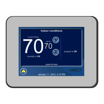
icomfort Toucht Thermostat − Technical Description and Features The 24VAC icomfort Toucht thermostat (figure 2) is an elec- iliary back−up heat are provided. Also, two stages of tronic communicating, color display touchscreen, 7−day pro- emergency heat are provided), grammable thermostat. It stores system parameters and set- supports Indoor Air Quality with time-based notification tings in a nonvolatile memory (i.e., it retains data when of consumables including media filters, UVC bulbs, hu-... -
Page 4: Installation And Setup (Setup Tab)
Please contact local etc. service technician. Dealer Name Lennox Repairman Possible cause is a wiring fault & Figure 4. Alert window − System settings (figure 5) appear first. As you use the up/... -
Page 5: Setting Time And Date
Setting time and date Use the arrows to select Time and Date; press edit (see fig- NOTE − After setting the time and date, if you don’t need to ure 7). Press next step to proceed to the Set current time add any non−communicating devices, you may wish to accept and date"... -
Page 6: Adding / Removing Non−Communicating Devices
Adding or Removing Non−Communicating Equipment Add or Remove Non−Communicating Equipment Outdoor Unit Type default is underlined Use this option to add any non−communicating outdoor unit current value is checked Not Installed and any non−communicating accessory. Press the yes button 1 Stage A/C Unit on this screen (figure 10) to access a list of non−communicat- 2 Stage A/C Unit ing devices to be installed or removed. -
Page 7: Adding And Configuring Devices Adding A Non−Communicating Outdoor Unit
Adding a humidifier If you do not have the ability to select or adjust the Humid- ity RH setpoint on the Indoor Humidity" tab, the control This procedure describes how to add a non−communicating is set for Display Only." In the installer program, go the humidifier controlled by the icomfortt Touch thermostat equipment tab and select System 49W95"... -
Page 8: Configuring Humidifier Or Dehumidifier
Configuring Humidification or Dehumidification Control Modes NOTE − You may access the Device Adjustment screen [fig- Depending on the type of equipment installed, the lists of op- ure 17] during initial setup or through the equipment tab if you tions may be different than those shown in figure 18. In order for either or both of these controls to display in the indoor hu- skip this during the initial setup. -
Page 9: Humidification / Dehumidification Modes
Explanation of Humidification and Dehumidification Modes HUMIDIFICATION modes outdoor sensor must be installed and set up NOTE − Do not use Steam Humidifier in Precision mode hu- dehumidification has been enabled on installer settings, midification. the unit is in COOL mode, (or if in AUTO, at least one ther- BASIC &... -
Page 10: Modifying Communicating Device Settings
Modifying communicating device settings Use this screen (figure 21) to access communicating devices’ The returning screen may appear with the message in red settings. Use back to return to the previous screen or next please view and save all red settings." Use the arrows to step to go on. -
Page 11: Using The Test Features
Using the Tests features NOTE − Test mode lasts for 30 minutes except for the defrost Also, note that there are now two buttons along the bottom labeled remove and start. Use remove to deselect a se- test, which lasts 30 seconds. Tests feature provides the tech- lected test. -
Page 12: Setting Up Equipment Parameters (Equipment Tab)
Table 2 on (on Page 21) shows a list of Editable Parameters Setting up Equipment parameters for the currently available devices designed to communicate in this system. Other devices and additional parameters may This feature allows the installer to edit details of devices in the be added at a later date. -
Page 13: Using The Diagnostic Features
Use the arrow buttons to scroll through the list of items found Lock In 2nd stage HP by Outdoor Temp default Off (heat on the left of the screen. Then press select. The right side of pump stage 2 operates normally). Use this setting to lock in the screen shows which item is selected (figure 34). -
Page 14: Viewing And Clearing Alerts
Viewing and clearing Installer Alerts NOTE − If the following screen appears, check all wiring for alert description active alerts correct connections. ALERT 1 of 5 Moderate Alert Code : 120 Thermostat is unable to remind later Thermostat reports: communicate to system Unresponsive components Indoor Unit... - Page 15 After selecting a time period using either method and press- Using remind later" ing set, the Cleared alert confirmation" screen (figure 39) ap- You may chose remind later and select from Remind later pears. options" list (see figure 41) or set a custom time as described earlier (see figure 40).
- Page 16 (Figure 46). Press yes to pro- Lennox" logo and hold for 5 seconds (see figure 45). The ceed (no returns to the home screen). system will access the installer screens.
-
Page 17: Accessing Installer Program From User Home Screen 16 Reconfiguring A System
Reconfiguring a system If any component of the HVAC system has been changed, While reconfiguring, the thermostat will have retained set- e.g. replacing an outdoor sensor, reconfiguring the system tings from the previous configuration. If a device has been re- will be required. -
Page 18: Smooth Setback Recovery (Ssr)
Smooth Setback Recovery (SSR) The Smooth Setback Recovery (SSR) feature ensures a Rules for SSR: smooth transition to a target program schedule setpoint. The 1. SSR is enabled when both Smooth Setback Recovery" SSR looks 2 hours (maximum recovery time) ahead for the is set to enabled (default) and the program schedule is target program schedule period’s set point. -
Page 19: Heat Pump, Dual Fuel And Balance Points
Heat Pump, Dual Fuel and Balance Points NOTE − The Balance Points feature requires an outdoor sen- point temperature. The set point can be adjusted in 1.0°F steps. Again, the Balance Points feature is only available if an sor to be installed and enabled. The outdoor temperature outdoor sensor is installed (standard on icomfortt−enabled sensor is included in all icomfortt−enabled heat pumps. -
Page 20: Gas Heat Control Mode
Gas Heat Control Mode Modulating Control of Gas Heat Table 1 details the furnace operation in the modulating mode. The thermostat includes a feature that provides modulating Staged operation control of the gas heat mode. The purpose of modulating con- Some furnaces provide up to four stages of gas heat opera- trol is to keep the room temperature at, or near, the desired tion. -
Page 21: Adjustable Parameters Table (User And Installer)
Table 2. Adjustable Parameters Table (Installer) Installer Parameter Name: Default Parameter Value Setting Increment entry SYSTEM (Go to EQUIPMENT tab and scroll to SYSTEM 49W95.) NOTE − All of the following changes are made on the stat. Equipment Name (Typewriter input screen) Filter 1 Timer Selection Calendar Time Calendar Time, Run Time... - Page 22 Table 2. Adjustable Parameters Table (Installer) Installer Parameter Name: Default Parameter Value Setting Increment entry OUTDOOR EQUIPMENT (Go to EQUIPMENT tab and scroll to HEAT PUMP or AIR CONDITIONER.) (Typewriter input screen = up to 35 characters in Equipment Name (HP & AC) Outdoor Unit string) Compressor Short Cycle Delay...
- Page 23 Table 2. Adjustable Parameters Table (Installer) Installer entry Parameter Name Default Min. Max. Incr. Dependency Note FURNACE Heating indoor blower OFF DIP SW None DIP switch setting in delay Non−comm. Heating indoor blower ON None 45 sec fixed in Non− delay Comm.
- Page 24 Table 2. Adjustable Parameters Table (Installer) Installer entry Parameter Name Default Min. Max. Incr. Dependency Note Cooling Airflow Settings High Cooling Airflow (CFM @ OU tons Outdoor Unit 1/2 HP blower 100% cool) (OUNC) * present 400CFM 1 HP blower Low Cooling Airflow (CFM @ (See Note 2+ stage...
- Page 25 Daylight Saving Enabled Enabled, Disabled Time* Circulate Fan − Per- centage of Time 15 to 45% Dealer Contact In- formation – Name* Lennox (Typewriter input screen) Address (Typewriter input screen) 1−800−9−LEN- Phone (Typewriter input screen) Email (Typewriter input screen) www.len-...
-
Page 26: Alert Codes And Troubleshooting
An unknown device is seen on the subnet in or outside of configuration − [any unit] mode. Clear by reconfiguring the system. Press and hold Lennox Logo, press setup tab, press start, and press confirm. If problem persists, then check all DEVICE connections to make sure they are icomfort−compatible. - Page 27 Table 4. Alert Codes and Critical alerts are displayed on Home (user) screen, in the Homeowner alert tab, and in Troubleshooting the Installer alert tab. Minor and Moderate alerts are found only in the Installer alert tab. Alert ID Message Name Priority Action required to Clear/Recover (Furnace / Air Handler)
- Page 28 Table 4. Alert Codes and Critical alerts are displayed on Home (user) screen, in the Homeowner alert tab, and in Troubleshooting the Installer alert tab. Minor and Moderate alerts are found only in the Installer alert tab. Alert ID Message Name Priority Action required to Clear/Recover (Furnace) Gas Valve 2...
- Page 29 Table 4. Alert Codes and Critical alerts are displayed on Home (user) screen, in the Homeowner alert tab, and in Troubleshooting the Installer alert tab. Minor and Moderate alerts are found only in the Installer alert tab. Alert ID Message Name Priority Action required to Clear/Recover (Furnace) Limit Open >...
- Page 30 Table 4. Alert Codes and Critical alerts are displayed on Home (user) screen, in the Homeowner alert tab, and in Troubleshooting the Installer alert tab. Minor and Moderate alerts are found only in the Installer alert tab. Alert ID Message Name Priority Action required to Clear/Recover (Air Handler) Electric Heat not...
-
Page 31: Troubleshooting Tips
Table 4. Alert Codes and Critical alerts are displayed on Home (user) screen, in the Homeowner alert tab, and in Troubleshooting the Installer alert tab. Minor and Moderate alerts are found only in the Installer alert tab. Alert ID Message Name Priority Action required to Clear/Recover (Outdoor Unit) - Page 32 Bold text indicates a tab, button, or text display on the thermostat. Table 5. Troubleshooting Tips Issue / Problem Possible Cause Corrective Action / Comments A humidifier was added to the Humidification Control − In the installer program, select the equipment tab. Select system as non−communicating Mode is set for "Display System 49W95 from the device list using the up/down...
- Page 33 The icomfort system does Replace the icomfort thermostat with a conventional ther- provide me a choice to add a not have the ability to con- mostat that has a dual fuel control mode (e.g. Lennox non−communicating heat pump trol a non−communicating ComfortSenset 7000).
-
Page 34: Wiring Diagrams
Lennoxt Outdoor Condensing Unit or Heat Pump Wire gauge of RSBus wire is 18. Wiring Diagrams icomfortt Communicating Indoor/non−Communicating Outdoor System Wiring icomfort by Lennoxt AIR HANDLER (AHC) icomfort by Lennox FURNACE (IFC) OR AIR HANDLER (AHC) OPTIONAL DIS- OPTIONAL DIS- OPTIONAL OUT-... - Page 35 Optional Accessories Wiring for use with any icomfort by Lennoxt system NOTE: icomfort Toucht THERMOSTAT SENSES HUMID- icomfort by Lennoxt ITY & CONTROLS 24V H" OUTPUT (& 120V H" OUT- FURNACE (IFC) OR PUT) TO CYCLE HUMIDIFIER BASED ON DEMAND. NO AIR HANDLER (AHC) OTHER CONTROL OR HUMIDISTAT REQUIRED.
-
Page 36: Configuring Heat Strips On Air Handler Control
Configuring heat strips on Air Handler Control (AHC) IMPORTANT: After electric heat strips are installed, the Air At this point, the icomfort Toucht will now detect the heat Handler Control (AHC) must be manually configured to detect strip information stored in the AHC. the number of electric heat sections. - Page 37 (if so desired, you may choose to TEST ALL) and press system. the select button. (If selecting individual tests, repeat un- 4−conductor thermostat wire from the icomfort Touch til you have selected all you intend to run.) thermostat to the gas furnace (R, i+, i−, C) 4−conductor thermostat wire from the integrated fur-...
- Page 38 Either make 4−conductor thermostat wire from the icomfort Touch changes or not, but press save either way. The red set- thermostat to the gas furnace (R, i+, i−, C) tings will go away after pressing save.
- Page 39 TIPS system. High & Low Balance points are enabled and adjusted un- 4−conductor thermostat wire from the icomfort Touch der the installer section of the thermostat. In the equip- thermostat to the gas furnace (R, i+, i−, C) ment tab select System 49W95" and press edit. Scroll 4−conductor thermostat wire from the furnace termi-...
- Page 40 If the thermostat System Setting" does not offer a choice system. for emerg. heat" and or the electric heat will not function; 4−conductor thermostat wire from the icomfort Touch the electric heat has not been configured. Configure the thermostat to the air handler (R, i+, i−, C) electric heat as described on Page 36, or for complete 4−conductor thermostat wire from the air handler ter-...
- Page 41 10. Test the system operation and confirm the system is elec- accessories being installed with the system. trically energized and operational. Particularly, test the 4−conductor thermostat wire from the icomfort Touch heat strips (when used) to insure the auxiliary stages thermostat to the air handler (R, i+, i−, C) have been detected and are operational.
- Page 42 TIPS system. If the thermostat System Setting" does not offer a choice 4−conductor thermostat wire from the icomfort Touch for emerg. heat" and or the electric heat will not function; thermostat to the air handler (R, i+, i−, C) the electric heat has not been configured. Configure the 4−conductor thermostat wire from the air handler ter-...
-
Page 43: Replacement Controls
11. Test the system operation and confirm the system is elec- system. trically energized and operational. Particularly, test the 4−conductor thermostat wire from the icomfort Touch heat strips (when used) to insure the auxiliary stages op- thermostat to the air handler (R, i+, i−, C) erate as designed. - Page 44 REVISION HISTORY Date Revision description 10−2010 Smooth setback recovery section added. Heat Pump, Dual Fuel, Balance Point operation section added. G71, SLP98, SL280 (future, by end of 2010) Furnace support added. Clarifications to alert code & troubleshooting and wiring diagrams. Standardized product nomenclature.
Need help?
Do you have a question about the icomfort Touch and is the answer not in the manual?
Questions and answers