
Subscribe to Our Youtube Channel
Related Manuals for Samson TROVIS 5100


Summary of Contents for Samson TROVIS 5100
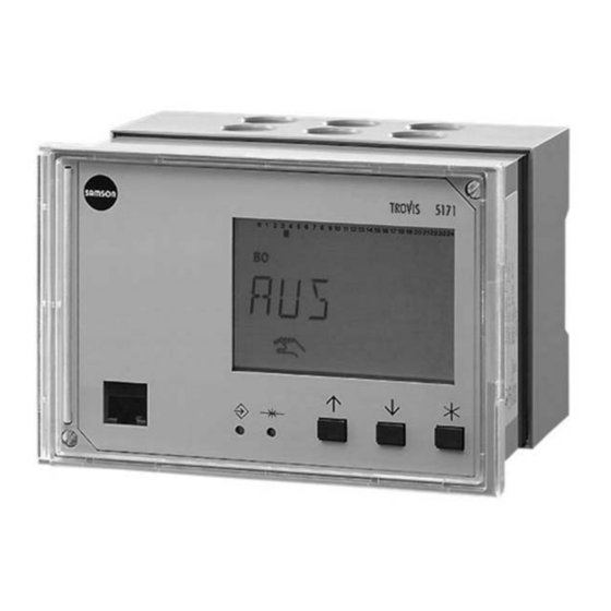
- Page 1 Automation System TROVIS 5100 Control and Processing Unit TROVIS 5171 Mounting and Operating Instructions EB 5171 EN Firmware version 1.1x ® Edition November 2005 Electronics from SAMSON...
- Page 2 Moreover, we do not guarantee that the buyer can use the product for an intended purpose. SAMSON rejects any liability for claims by the buyer, especially claims for compensation including lost profits or any other financial loss, except the damage was caused intentionally or by gross negligence.
-
Page 3: Table Of Contents
Contents Contents Operation ....... 5 Operating elements......5 1.1.1 Operating keys . - Page 4 Contents 10.2 Parameter list ......40 10.3 Sensor resistance tables ......44 10.4 Technical data .
-
Page 5: Operation
Operation Operation The TROVIS 5171 Control and Processing Unit (Programmable Logic Controller = PLC) is freely programmable. The controller is delivered without an executable program in the mem- ory. The application must be developed separately for the desired purpose on the PC using ®... -
Page 6: Display
Operation Display After switching on and during operation, the PLC is in the operating level. When the applica- tion is active, either the name of the application or a customer-specific menu is displayed. ® This menu can be customized to meet your specific needs in the ISaGRAF application. -
Page 7: Displaying Data
Operation Displaying data The states of the inputs and outputs, the available memory as well as information on fault alarms and communication can be retrieved in the info level. The following levels provide information on the device status: FREI _ _ _ KB: Free memory;... -
Page 8: Setting The Controller Time
Operation Setting the controller time The current time and date need to be set immediately after start-up and after a power failure lasting more than 24 hours. The time is set in PA5 parameter level. Proceed as follows: 3s Switch to configuration and parameter level. 0 1 2 3 4 5 6 7 8 9 10 11 12 13 14 15 16 17 18 19 20 21 22 23 24 Display shows: PA5 Open PA5 parameter level. -
Page 9: Setting The Times-Of-Use
Operation Select END . Exit PA5 parameter level. Select END . Exit configuration and parameter level. Display shows: controller time Select END . Switch to operating level. Display shows: name of the application or customer-specific menu Note! If no key is pressed for two minutes, the PLC returns to operating level. Setting the times-of-use The controller provides 12 times-of-use that can be utilized separately. - Page 10 Operation 3s Switch to configuration and parameter level. Proceed as follows: Display shows: PA5 Open PA5 parameter level. Display shows: controller time 0 1 2 3 4 5 6 7 8 9 10 11 12 13 14 15 16 17 18 19 20 21 22 23 24 Select desired times-of-use (ZEIT 1 to ZEIT 12), e.g.
- Page 11 Operation Note! Do not use the Mo -- So menu to check the programmed times-of-use. If this menu is opened after the times-of-use have been set, the usage times programmed for each day of the week are reset to their default settings. Select END .
-
Page 12: Start-Up
® environment, refer to the documentation in- cluded in the software package. To enable simple and clear programming, ready-made functions and function blocks are available from SAMSON. ® Note! In ISaGRAF , internal variables can be assigned (hexadecimal) network addresses. -
Page 13: Activating And Deactivating Functions
Start-up Activating and deactivating functions A function is activated over the associated function block. The numbers 0 to 24 in the top row of the display represent the respective function block numbers. When a configuration level is opened, the activated function blocks are indicated by a black square on the right-hand side below the function block number. - Page 14 Start-up Proceed as follows: Change settings and confirm changes. If applicable, the following function block parameter is displayed. Once all parameters have been confirmed, the opened function block is closed. To set further function blocks, repeat the instructions in the fields highlighted in gray. Select END.
-
Page 15: Changing Parameters
Start-up Changing parameters Depending on the activated functions, not all parameters listed in the Appendix (–> sec- tion 10.2) might be available. The parameters are grouped by topics: PA1…4 Do not exist Controller time, times-of-use Does not exist LON communication (in devices with LON interface and CO7 ->... -
Page 16: Entering The Key Number
Start-up Entering the key number Some functions are protected against unintentional and unauthorized access by a key num- ber. The key number, which is required to activate and deactivate protected functions, can be found on page 49. To avoid unauthorized use, remove the page or make the key number unreadable. - Page 17 Start-up diagram (–> page 37). The function block for the selected sensor is activated and the func- tion block parameter associated with the type of input signal is selected. If the temperature values displayed by the PLC deviate from the actual temperatures, the measured values of the connected sensors can be changed or reset.
-
Page 18: Resetting To Default Values
Start-up Switch to operating level. Display shows: name of the application or customer-specific menu Resetting to default values All parameters and function blocks that were set without previously entering the key number can be reset to their default values (factory settings) from configuration and parameter level. Important! ®... -
Page 19: Manual Operation
Manual operation Manual operation All outputs are configured in manual operating mode (see wiring diagram in section 9). Proceed as follows: 3s Switch to configuration and parameter level. Display shows: PA5 Select END . Switch to info level. Display shows: controller time Select Hand . -
Page 20: System-Wide Functions
System-wide functions System-wide functions Automatic summer time/winter time changeover The time is automatically adapted on the last Sunday in March at 2.00h and on the last Sunday in October at 3.00h. Configuration Function CO5 -> F05 = ON Summer time/winter time changeover EB 5171 EN... -
Page 21: Operational Faults
Operational faults Operational faults If the corresponding universal inputs are configured as sensors using CO6 -> FB01 to FB17 = ON, a sensor failure can be detected, processed, and indicated (text message, fax). Error status register In the INF8 level, the bits of the error status register are indicated. The error status register (holding register - 16 bit) HR 60 serves as indicator for faults of the controller or the plant. -
Page 22: Fault Alarms
Operational faults Fault alarms Fault alarms can be forwarded either directly to the process control station over a modem, to a mobile phone over the SMS function or to a fax machine. Only one function (Modbus, SMS or fax function) can be selected at a time as the functions use the same interface. Fault alarms forwarded to a mobile phone or fax contain the number of the affected error status register (FSR1), the fault as specified in the error status register (BitNo), the short des- ignation of the device, and the bit number (Bit xx). -
Page 23: Sending Fax In Case Of A Fault Alarm
Operational faults Parameters Default Parameter level/Range of values Access number (ZUGNO) – PA9 / Freely configurable* Recipient’s mobile phone no. (HANDY) – PA9 / Freely configurable** Numbers 0 to 9, P = pause, - = end, max. 22 characters ** Numbers 0 to 9, P = pause, - = end, max. 14 characters 5.2.2 Sending fax in case of a fault alarm The device type is forwarded in addition to a detailed error description. -
Page 24: Communication
(1400-7139). - Operation on a four-wire bus To link the controller and the bus line, the signal level needs to be converted by an appropri- ate converter (SAMSON cable converter 1400-7308). RS232 RS 232C RS 232C... -
Page 25: Rs-232-C System Bus Interface
Communication RS-232-C system bus interface The system bus connection is located on the rear panel of the controller housing (RJ 12 con- nector). The device can be connected either directly to the serial interface of a PC (point-to-point connection) or to a (dial-up) modem. A dial-up modem is required if the con- troller is to be connected to the telecommunications network. -
Page 26: System Bus Interface With Rs-232/Rs-485 Cable Converters (For Four-Wire Bus)
Communication Parameters* Default Parameter level/Range of values No. of redialing attempts (C) PA9 / 0 to 99 Phone no. of control station (TELNO) – PA9 / Freely configurable** Alternative phone no. (RESNO) – PA9 / Freely configurable** ** Numbers 0 to 9, P = pause, - = end, max. 22 characters * –>... -
Page 27: Description Of Communication Parameters To Be Adjusted
Communication Description of communication parameters to be adjusted Station address This address is used to identify the PLC in bus or modem operation. In a system, each con- troller needs to be assigned a unique address. Baud rate In a bus system, baud rate refers to the transfer speed between the control system and the PLC. - Page 28 Communication Phone no. of control station (TELNO) Enter the phone number of the control system’s modem, if required including the dialing code. Short pauses between the numbers can be entered using P (= 1 second); “–“ indicates the end of the string. The phone number can include max. 22 characters. Example: “069, 2 sec.
-
Page 29: Meter Bus Interface
Communication GND TD DTR Fig. 3 · Pin assignment, RJ-12 system bus interface Meter bus interface Thanks to the meter bus interface, the PLC can communicate with up to 3 heat and water me- ters according to EN 1434-3. Details on the use of the different heat and water meters can be found in the technical docu- mentation TV-SK 6311. - Page 30 Communication In INF9 info level, “1434“ is displayed when the meter bus is activated. Press the enter key to get to the display referring to the meter bus. For each of the three heat meters whose address is not 255, “buSi“ (with i = 1, 2, 3) is indicated. Press the enter key again to display the fol- lowing information about the associated meter: Flow rate (d, cm/h) Total capacity (U, cm...
-
Page 31: Lon Communication
LON active CO7 -> FB00 = ON In INF7 info level, all other TROVIS 5100 devices are listed with their controller type and LON address (e.g. “74-01“). If the display blinks, a fault occurred during communication. Sending outdoor temperatures and the controller time Two outdoor temperatures and the controller time can be made available on the LON bus to be adopted by the other controllers. - Page 32 LON communication Transmitting the controller time The controller time can be made available to all LON devices. They read the transmitted con- troller time and adopt it. The controller time is sent using CO7 -> FB02 = ON. This function may only be activated in one LON device;...
-
Page 33: Installation
Installation Installation The controller consists of the housing with the electronics and the back panel with the termi- nals. It is suitable for panel, wall, and top hat rail mounting (Fig. 4). Panel mounting 1. Remove both screws (1). 2. Pull apart the controller housing and back panel. 3. - Page 34 Installation Panel mounting Back panel of the controller Controller housing Wall mounting Top hat rail mounting Dimensions in mm W x H x D = 144 x 96 x 111 Fig. 4 Installation EB 5171 EN...
-
Page 35: Electrical Connection
Surge diverters must be installed at the control cabinet inlet. Noise suppression The TROVIS 5171 Controller with SAMSON actuator is interference suppressed according to VDE 0875. If different actuator makes are used, or moreover, further actuators with interfer- ence sources are used in a plant, the operator/supplier of a custom-made plant must make sure that the entire plant complies with VDE 0875 regulations due to the legal obligation of ensuring interference suppression. - Page 36 The connection of LONMARK devices requires additional software. The devices are connected to terminals 1 and 2. On using LONMARK devices, the SAMSON LON is not available. In this case, CO7 -> FB00 = OFF must be configured. Meter bus The meter bus is connected to terminals 48, 49, and 50.
- Page 37 Electrical connection EB 5171 EN...
-
Page 38: Appendix
Appendix Appendix 10.1 Function block list CO5: General functions 5 Summer time/winter ON CO5 -> FB05 = ON: Automatic summer time/winter time time changeover changeover active CO6: Configuring the universal inputs FB Function WE Comment 00 Sensor configuration, ON CO6 -> FB00 = ON: Pt100 and/or Pt1000 global CO6 ->... - Page 39 Appendix CO8: Fault initialization (changes require the key number) FB Function WE Comment 00 Dial-up also upon OFF CO8 -> FB00 = ON: Dial-up to the building control station both corrected fault when a fault was detected and a fault was corrected CO8 ->...
-
Page 40: Parameter List
Appendix Meter bus #1 OFF CO9 -> FB21, 22, 23 = ON: Function block parameters: Meter bus address WMZ_ / 0 to 255 (255) Meter bus #3 Model code WMZ_ / P15, PS2, 1434, CAL3, APAtO, SLS, (1434) Reading mode WMZ_ / 24h, con, CoiL (con) FB Function block, WE Default settings 10.2 Parameter list PA5: General parameters... - Page 41 Appendix Times-of-use 0 1 2 3 4 5 6 7 8 9 10 11 12 13 14 15 16 17 18 19 20 21 22 23 24 PA7: LON communication (only in devices with LON interface and CO7 -> FB00 = ON) Parameter designation Display Range of values (default settings)
- Page 42 Appendix Parameter designation Display Range of values (default settings) Cyclical initialization (I) 0 1 2 3 4 5 6 7 8 9 10 11 12 13 14 15 16 17 18 19 20 21 22 23 24 0 to 255 min (5 min) Only with CO9 ->...
- Page 43 Appendix Parameter designation Display Range of values (default settings) CO9 -> FB01 = ON: Alternative phone no. 0 1 2 3 4 5 6 7 8 9 10 11 12 13 14 15 16 17 18 19 20 21 22 23 24 Max.
-
Page 44: Sensor Resistance Tables
Appendix 10.3 Sensor resistance tables Resistance values with PTC resistors Type 5224 Outdoor Temperature Sensors, Types 5264 and 5265 Flow and Return Flow Temperature Sensors, Type 5264 Storage Tank Temperature Sensors –20 –10 °C Ω 694 757 825 896 971 1010 1050 1132 1219 1309 1402 1500 1601 1706 1815 1925 Resistance values with Pt 1000 resistors Type 5227-2 Outdoor Temperature Sensors, Type 5277-2 (thermowell required) and Type 5267-2 (contact sensor) Flow, Return Flow and Storage Tank Temperature Sensors. -
Page 45: Technical Data
Appendix 10.4 Technical data Voltage supply 230 V AC, 48 to 62 Hz Power consumption Approx. 8 VA Motorola 68000 Program memory 128 KB Random Access Memory (RAM) 512 KB Flash memory 1 MB Clock cycle Approx. 500 ms (reading all inputs) Timer 4 ms Universal inputs... - Page 46 Appendix Interfaces LON: Communication with other TROVIS 5100 Series Controllers RS-232: Modem connection Meter bus (M-Bus): Connection with 15 V DC voltage supply for heat meter used to limit the flow rate/capacity RJ 45 connector: Interface for connection to a PC...
-
Page 47: Customer Data
Appendix 10.5 Customer data Station Operator Relevant SAMSON office Function blocks FB00 FB01 FB02 FB03 FB04 FB05 FB06 FB07 FB08 FB09 FB10 FB11 FB12 FB13 FB14 FB15 FB16 FB17 FB18 FB19 FB20 FB21 FB22 FB23 EB 5171 EN... - Page 48 Appendix Times-of-use (PA5) Time-of-use 1 Time-of-use 2 Time-of-use 3 Time-of-use 4 Start – Start – Start – Start – Start – Start – Start – Start – Stop (1) Stop (2) Stop (1) Stop (2) Stop (1) Stop (2) Stop (1) Stop (2) Time-of-use 5 Time-of-use 6...
- Page 49 Appendix Parameters Parameter PA7 Value range LON communication 1 to 20 Parameters PA9 Value range Station address (ST NR) 1 to 247 Baud rate (BAUD) 300 to 19200 Cyclical initialization (I) 0 to 255 min Modem dialing pause (P) 1 to 255 min Modem time-out (t) 0 to 255 min No.
-
Page 50: Index
Index Index Info level ......7 Inputs, configuration....16 Arrow key(s) . - Page 51 Index Redialing attempts ....27 Reset key ......5 Sensor calibration .
- Page 52 EB 5171 EN...
- Page 53 Operating level (name of the application or customer-specific menu) Hand Configuration Controller INF9 Info level time parameter level Free INF8 memory INF7 INF1 INF1: Analog inputs and outputs PA5: Controller time, times-of-use Binary inputs and outputs PA7: LON communication* INF7: LON communication* PA9: Modbus/meter bus communication...
-
Page 54: Frequently Used Abbreviations
Frequently used abbreviations Analog output (AO) Instruction List ® (ISaGRAF programming language) Analog input (AI) Ladder Diagram Binary output ® (ISaGRAF programming language) Binary input Local Operating Network Configuration level Parameter level Function block Programmable Logic Controller Function Block Diagram Sequential Function Chart ®... - Page 56 SAMSON AG · MESS- UND REGELTECHNIK Weismüllerstraße 3 · 60314 Frankfurt am Main · Germany Phone: +49 69 4009-0 · Fax: +49 69 4009-1507 EB 5171 EN Internet: http://www.samson.de...
Need help?
Do you have a question about the TROVIS 5100 and is the answer not in the manual?
Questions and answers