Festo OVEM LK Series Operating Instructions Manual
Vacuum generator
Hide thumbs
Also See for OVEM LK Series:
- Operating instructions manual (50 pages) ,
- Instructions & operating (50 pages)

Subscribe to Our Youtube Channel
Related Manuals for Festo OVEM LK Series


Summary of Contents for Festo OVEM LK Series
- Page 1 Vakuumsaugdüse Vacuum generator OVEM-…-LK Bedienungsan leitung Operating instructions 8058875 1602NH [8058876]...
- Page 2 ..........Festo – OVEM-…-LK – 1602NH...
-
Page 3: Table Of Contents
..............Festo – OVEM-…-LK – 1602NH Deutsch... - Page 4 ........... . Festo – OVEM-…-LK – 1602NH Deutsch...
-
Page 5: Produktbeschreibung
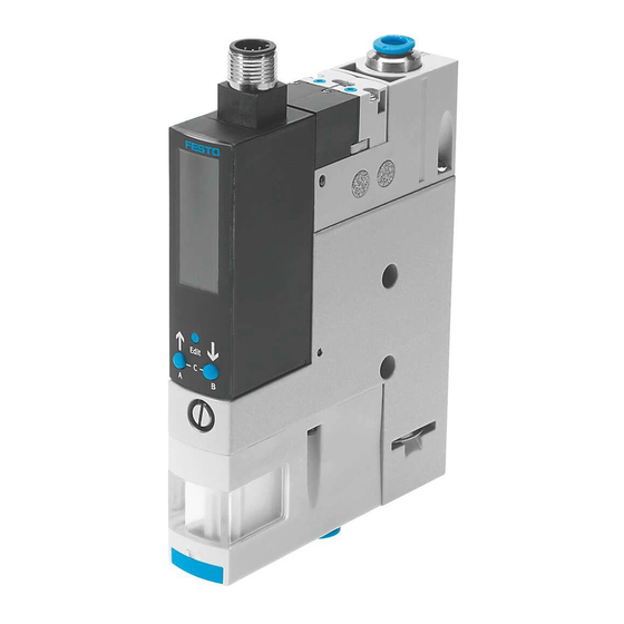
Drosselschraube zur Regulierung des Abwur Magnetventile fimpulses Druckluftanschluss (1) Vakuumsensor mit LCD-Anzeige und Be Abluftanschluss / Schalldämpfer (3) dientasten (è Fig. 13) Vakuumanschluss (2) Elektrischer Anschluss Gehäuse mit Befestigungsbohrungen Fig. 1 Bedienteile und Anschlüsse Festo – OVEM-…-LK – 1602NH Deutsch... -
Page 6: Merkmale
Steckverschraubungen, Abluftanschluss mit offenem Schall dämpfer Ruhestellung der NO, stromlos offen (Vakuumerzeugung) mit Abwurfimpuls Vakuumsaugdüse NC, stromlos geschlossen (keine Vakuumerzeugung) mit Abwurfimpuls Elektrischer Anschluss Stecker M12 (5-polig) Vakuumsensor IO-Link Alternative Vakuumanzeige - InHg Tab. 1 Variantenübersicht Festo – OVEM-…-LK – 1602NH Deutsch... -
Page 7: Sicherheit
– IO-Link Parameter und Funktionen gemäß SmartSensor Profile (è Kapitel 4). – 2 binäre Datenkanäle zur Programmierung der Schaltfunktionen und des Schaltverhaltens. SIO Modus: Lokale Konfiguration über die Bedientasten. Im SIOModus hat die OVEM die Funktion einer 2PVariante (1 Schalteingang, 2 Schaltausgänge). Festo – OVEM-…-LK – 1602NH Deutsch... -
Page 8: Schaltfunktionen
(SP1, SP2) Teach-Modus – 2 Teachpunkte (TP1, TP2) TP1=SP1 TP2=SP2 TP1=SP2 TP2=SP2 1) TP1 = kleinerer Wert, TP2 = größerer Wert, unabhängig von der Teach-Reihenfolge Tab. 3 Fensterkomparator: Einstellung Schaltpunkte SP1, SP2 und Hysterese HY Festo – OVEM-…-LK – 1602NH Deutsch... -
Page 9: Ventilsteuerung
Auto-Drop aktiv Auto-Drop inaktiv Auto-Drop Auto-Drop Ventilfunktion OVEM-...-OE Auto-Drop aktiv Auto-Drop inaktiv Auto-Drop Auto-Drop Steuersignal BCS1 / Schalteingang DI1 Schaltzustand Magnetventil Abwurfimpuls Steuersignal BCS2 Vakuumanschluss (2) Schaltzustand Magnetventil Vakuum Dauer Abwurfimpuls Fig. 2 Schaltverhalten Ventilsteuerung Festo – OVEM-…-LK – 1602NH Deutsch... -
Page 10: Luftsparfunktion
Belüftungszeiten). Die zeitliche Überwachung kann über die Einstellung der Grenzwerte SP1 (Evaku ierungszeit) und SP2(Belüftungszeit) in BDC4 aktiviert werden (è Tab. 9). Die Schaltzustandsinformation des BDC4 ist nicht in den Prozesseingangsdaten (Process data IN) enthalten. Festo – OVEM-…-LK – 1602NH Deutsch... -
Page 11: Messgrößen
50 mbar Transportzeit Rückfahrzeit BCS1/DI BDC1 oder BDC2 / Out A Ventil Vakuum Ventil Abwurfimpuls Schaltpunkt SP1 (BDC1 oder BDC2) Evakuierungszeit Rückschaltpunkt RSP1 (BDC1 oder BDC2) Belüftungszeit Fig. 4 Taktzyklus (Beispiel für Out A (Air-save)) Festo – OVEM-…-LK – 1602NH Deutsch... -
Page 12: Teach-Funktion (Teach-In)
Zeiten gemittelt. Nach dem Stopp des Teach-In wird auf die gemittelten Werte eine Funktionsreserve von 100% addiert. 50 mbar Teach Teach Start Stop Ventil Vakuum Transportzeit Taktzyklus 1 Rückfahrzeit Taktzyklus 2 Taktzyklus N Fig. 5 Funktionsweise Dynamisches Teach-In Festo – OVEM-…-LK – 1602NH Deutsch... -
Page 13: Datenspeicherung (Data Storage)
– Übertragung von Blockparametern durch Start- und Endebefehle (è Tab. 15). – Während der Übertragung werden Parameteränderungen (z. B. durch Teach-In) blockiert. – Im Fall eines ungültigen Parametersatzes werden die geänderten Parameter verworfen und der vorherige Parametersatz wieder aktiviert. Festo – OVEM-…-LK – 1602NH Deutsch... -
Page 14: Parameterbeschreibung
VendorID2 (LSB) 0x4D 0x09 DeviceID1 (MSB) 0x00 Geräte-Identifikation 0x0A DeviceID2 0x00 0x0B DeviceID3 (LSB) Gerätevariante OVEM-...-H-...-OE Gerätevariante OVEM-...-L-...-OE Gerätevariante OVEM-...-H-...-CE Gerätevariante OVEM-...-L-...-CE 1) R = Lesen Tab. 5 Identifikation Direkte Parameter (Identification Direct Parameters) Festo – OVEM-…-LK – 1602NH Deutsch... -
Page 15: Prozessdaten (Process Data)
2) Werte: BCS2 = 0: Magnetventil Abwurfimpuls nicht geschaltet, BCS2 = 1: Magnetventil Abwurfimpuls geschaltet 3) Werte: BCS1 = 0: Magnetventil Vakuum nicht geschaltet, BCS1 = 1: Magnetventil Vakuum geschaltet Tab. 8 Prozessausgangsdaten (Process data OUT) Festo – OVEM-…-LK – 1602NH Deutsch... -
Page 16: Smart Sensor Profil Parameter (Smart Sensor Profile Parameters)
Teachpunkt TP1 für SP1 übernommen Teach state Aktueller Stand des Teach-In 1) R = Lesen, W = Schreiben, R/W = Lesen und Schreiben, DR = Geräteneustart (Device Reset) DS = Datenspeicherung (Data Storage) möglich Festo – OVEM-…-LK – 1602NH Deutsch... - Page 17 Single point mode (Standard) Window mode Switchpoint 0…14745 Hysteresewert hysteresis (0…-0,9 bar) Standardwert: 4096 (-0,25 bar) 1) R/W = Lesen und Schreiben, FR = Werkseinstellungen wiederherstellen (Factory Reset) DS = Datenspeicherung (Data Storage) möglich Festo – OVEM-…-LK – 1602NH Deutsch...
- Page 18 2) Zeit = 2,5 ms * Value 3) Wert = 128: vendor specific. Es werden 5 Messungen erfasst, bei 3 Überschreitungen wird ein Event als Warnung erzeugt Tab. 9 Smart Sensor Profile Parameter - (Smart Sensor Profile Parameters) Festo – OVEM-…-LK – 1602NH Deutsch...
-
Page 19: Geräteparameter (Device Parameters)
Standard: 80 (200 ms) 1) R/W = Lesen und Schreiben, FR = Werkseinstellungen wiederherstellen (Factory Reset), DS = Datenspeicherung (Data Storage) möglich. 2) Länge des automatischen Abwurfimpulses = 2,5 ms * Value Tab. 10 Geräteparameter (Device Parameters) Festo – OVEM-…-LK – 1602NH Deutsch... -
Page 20: Überwachungsparameter (Observation Parameters)
2) Bei aktivierter Luftsparfunktion (Air-saving function = ON), wird der Status des BDC1 ausgegeben Bei deaktivierter Luftsparfunktion (Air-saving function = OFF), wird der Status des BDC2 ausgegeben 3) Zeit = 2,5 ms * Value Festo – OVEM-…-LK – 1602NH Deutsch... -
Page 21: Diagnose (Diagnosis)
0x2010 Supply 7864 Aktuelle Spannungsversorgung des Geräts als voltage (24 V) Prozesswert 1) R = Lesen, DR = Geräteneustart (Device Reset) 2) Spannungswert = 50 V * Value/16283 Tab. 12 Allgemeine Diagnosemeparameter (Diagnosis) Festo – OVEM-…-LK – 1602NH Deutsch... - Page 22 BDC1 außerhalb der min. Grenzwerte, Luftsparfunktion deaktiviert 1) R = Lesen, DR = Geräteneustart (Device Reset) F = Event Typ Fehler, W = Event Typ Warnung Tab. 13 Index 0x0025: Ausführlicher Gerätestatus (Detailed Device Status, Event Codes) Festo – OVEM-…-LK – 1602NH Deutsch...
-
Page 23: Gerätekommandos (Device Commands)
Teach Cancel Abbruch aller Teach-In Sequenzen 0x80 Device Reset Warmstart des Geräts, Rücksetzen der Laufzeitparameter 0x82 Restore factory settings Rücksetzen der Konfiguration und der Parameter auf den ursprünglichen Zustand (Defaultwerte) Tab. 15 Befehlscode (Command Code) Festo – OVEM-…-LK – 1602NH Deutsch... -
Page 24: Einbau
M5 / M4 èTab. 16 max. 2,5 Nm max. 0,8 Nm Fig. 6 Direkte Befestigung seitlich Fig. 7 Direkte Befestigung hinten OVEM Befestigungsschrauben OVEM-...-05/ -07/ -10 OVEM-...-14/ -20 Tab. 16 Größe der Befestigungsschrauben bei direkter Befestigung seitlich Festo – OVEM-…-LK – 1602NH Deutsch... - Page 25 Zubehör Befestigungswinkel è www.festo.com/catalogue M5 / M4 èTab. 16 max. 2,5 Nm Fig. 9 Montage mit Befestigungswinkel Befestigung auf P-Anschlussleiste Die Befestigung auf einer P-Anschlussleiste mit maximal 8 Plätzen ist möglich (Montageanleitung OABM-P è www.festo.com/sp). Festo – OVEM-…-LK – 1602NH Deutsch...
-
Page 26: Pneumatisch
– OVEM-...-GN/GO: Minimale Innendurchmesser der Anschlussschläuche beachten (è Tab. 18). – Abluftanschluss nicht verschließen. – OVEM-...-07/-10/-14/-20: Bei Bedarf Schalldämpfer mit einer Schalldämpfer-Erweiterung verlängern (Zubehör è www.festo.com/catalogue ) – Empfehlung: Festo-Schläuche des Typs PUN verwenden (è www.festo.com/catalogue). Festo – OVEM-…-LK – 1602NH Deutsch... -
Page 27: Elektrisch
Grau (GY) Nicht belegt oder digitaler Eingang (PNP) 1) Bei Verwendung der Verbindungsleitung gemäß Zubehör (è www.festo.com/catalogue ) 2) Nach einem Fallback oder im SIO-Modus hat dieser Pin die Konfiguration eines digitalen Schaltausgangs 3) Dieser Pin ist im IO-Link Betrieb nicht belegt. Nach einem Fallback oder im SIO-Modus hat dieser Pin die Konfiguration eines digi... -
Page 28: Inbetriebnahme
Ändern des Betriebsdrucks ändert die Stärke des Unterdrucks am Vakuumanschluss. Damit kann das Vakuum am Sauggreifer eingestellt werden. Funktionen und Parameter können festgelegt werden: – im IO-Link Betrieb (è Kapitel 4) – manuell am Gerät (è Abschnitt 12.2.4) – durch Teach-In (è Abschnitt 12.2.5) Festo – OVEM-…-LK – 1602NH Deutsch... -
Page 29: Intensität Des Abwurfimpules Einstellen
Hinweis Bei Verwendung von großen Sauggreifern kann es physikalisch bedingt zum Aufbau eines geräteunabhängigen Vakuums kommen. Das Werkstück löst sich dann trotz aus reichend lang gewählter Dauer des Abwurfimpulses nicht vom Sauggreifer. Festo – OVEM-…-LK – 1602NH Deutsch... -
Page 30: Bedienung Und Betrieb
Rücksetzen mit Bedientasten am Gerät 1. Betriebsspannung ausschalten. 2. A-Taste + B-Taste + Edit-Knopf gleichzeitig drücken und gedrückt halten. 3. Betriebsspannung einschalten. 4. A-Taste + B-Taste + Edit-Knopf loslassen. è LCD-Anzeige zeigt [CLEA]. è Die Werkseinstellungen sind wiederhergestellt. Festo – OVEM-…-LK – 1602NH Deutsch... -
Page 31: Sicherheitscode Aktivieren
– Der Sicherheitscode schützt vor Eingaben über die Bedientasten lokal am Gerät. IO-Link-Parame trierung ist nicht betroffen. – Werkseinstellung: „OFF“. – Der Sicherheitscode wird bei Wiederherstellen der Werkseinstellungen zurückgesetzt. – Eingabe und Aktivierung im Edit-Modus (è Abschnitt 12.2.4). Festo – OVEM-…-LK – 1602NH Deutsch... -
Page 32: Fehlermeldungen Und Störungsbeseitigung
(z. B. höherer Energieverbrauch). Notbetrieb, Wartung dringend erforderlich. Logischer Kanal di1 Funktion ist nicht mehr gewährleistet. oder di2 ist aktiv Alle ansteuerbaren Ausgänge des Geräts sind inaktiv. Tab. 22 Diagnosestufen für Schaltausgang Out B und Display Festo – OVEM-…-LK – 1602NH Deutsch... -
Page 33: Fehlermeldungen Und Fehlercodes
• Parametrierung BDC1 / BDC2 prüfen Er40 0x5110 Versorgungsspannung zu hoch • Versorgungsspannung prüfen (Warnung) Er41 0x5111 Versorgungsspannung zu niedrig (Warnung) 1) Diagnosestufen Display 2) Status IO-Link Tab. 23 Fehlermeldungen, Fehlercodes, Diagnosestufen und Fehlerbeschreibung Festo – OVEM-…-LK – 1602NH Deutsch... -
Page 34: Störungen
Anzeige + [min] + [max] blin Diagnosestufe 2 aktiv ken gleichzeitig • è Kapitel 8.2 Anzeige blinkt und Fehler Diagnosestufe 3 aktiv code erscheint [Option] blinkt Teach-In fehlerhaft • Hysterese größer einstellen, Teach-In wiederholen Tab. 24 Festo – OVEM-…-LK – 1602NH Deutsch... -
Page 35: Ausbau
2. Schieber 1 vorsichtig bis zur ersten Raste herausziehen. Der Schieber muss in dieser Position am Filter verbleiben. 3. Filter 2 herausziehen. Bei Bedarf reinigen. 4. Filter in das Gehäuse schieben. 5. Schieber hineinschieben. è Der Filter wird durch den Schieber in die Vakuumsaugdüse geschoben. Festo – OVEM-…-LK – 1602NH Deutsch... -
Page 36: Technische Daten
Anzeige/Bedienung Einstellbereich Schwellwerte [bar] -0,999…0 Einstellbereich Hysterese [bar] -0,9…0 Umwelt / Umgebung Umgebungstemperatur [°C] 0…50 Mediumstemperatur [°C] 0…50 Betriebsmedium Druckluft nach ISO 8573-1:2010 [7:4:4] Hinweis zum Betriebsmedium geölter Betrieb nicht möglich Werkstoffhinweis RoHS konform Festo – OVEM-…-LK – 1602NH Deutsch... - Page 37 10…60 Hz: 0,35 mm / 60…150 Hz: 5g Schutzklasse Schutzart IP 65 Relative Luftfeuchtigkeit 5…85 Störaussendung nach EN 61000-6-4 Störfestigkeit nach EN 61000-6-2 Werkstoffe Werkstoffinformation Dichtungen Werkstoffinformation Gehäuse Alu-Druckguss, PA verstärkt Werkstoffinformation Steckergehäuse Messing, vernickelt Tab. 25 Festo – OVEM-…-LK – 1602NH Deutsch...
-
Page 38: Anhang
Symbolleiste für Funktionen (è Tab. 26) aktuellen Druckwerts bezogen auf den ma Segmentleiste rechts: Grafische Anzeige des ximalen Messwert des Messbereichs aktuellen Status der digitalen Eingänge bzw. des Ventilzustands(è Tab. 26) Fig. 13 LCD-Anzeige und Bedientasten Festo – OVEM-…-LK – 1602NH Deutsch... - Page 39 – Segment L16: Status des digitalen Schalteingangs DI1 (Saugen). Schaltein gang gesetzt, wenn Segment leuchtet. – Segment L18: Status des digitalen Schalteingangs DI2 (Abwurf ). Schaltein gang gesetzt, wenn Segment leuchtet. Tab. 26 Symbolik im Display Festo – OVEM-…-LK – 1602NH Deutsch...
- Page 40 über Bedientasten Magnetventil Vakuum geschaltet Segment L12 leuchtet und Symbol B Zusätzliche Funktion der elektrischen Handhilfs leuchten + Anzeige <FORC> betätigung über Bedientasten Magnetventil Abwurfimpuls (Eject) geschaltet Tab. 27 Beispiele für zusätzliche Anzeigen der Segmentleisten Festo – OVEM-…-LK – 1602NH Deutsch...
-
Page 41: Betriebszustände Und Menüstruktur
Bedeutung der Symbole zur Darstellung der Menüstruktur 12.2.2 RUN-Modus – Grundzustand nach dem Anlegen der Betriebsspannung – Anzeige des aktuellen Messwerts (Relativdruck) – Anzeige der Signalzustände der Magnetventile – Anzeige der gewählten Ein- und Ausgänge Festo – OVEM-…-LK – 1602NH Deutsch... -
Page 42: Show-Modus
– Anzeige der aktuellen Einstellungen – Anzeige und Löschen der minimalen und maximalen Druckwerte – Anzeige und Löschen der minimalen und maximalen Belüftungs- und Evakuierungszeit – Anzeige der Diagnosemeldungen Fig. 14 Menüstruktur SHOW-Modus im SIO-Modus Festo – OVEM-…-LK – 1602NH Deutsch... -
Page 43: Edit-Modus
OVEM-…-LK 12.2.4 EDIT-Modus – Einstellen von Parametern – Bedienen der elektrischen Handhilfsbetätigung (FORCE) Fig. 15 Menüstruktur Edit-Modus im SIO-Modus Festo – OVEM-…-LK – 1602NH Deutsch... -
Page 44: Teach-Modus
OVEM-…-LK 12.2.5 Teach-Modus – Übernehmen des aktuellen Messwerts zur Festlegung von Schaltpunkten Teach Start Teach Stop Fig. 16 Menüstruktur Teach-In im SIO-Modus Festo – OVEM-…-LK – 1602NH Deutsch... - Page 45 ..............Festo – OVEM-…-LK – 1602NH English...
- Page 46 ........... . . Festo – OVEM-…-LK – 1602NH English...
-
Page 47: Product Description
Supply port (1) Vacuum sensor with LCD display and operat Exhaust port / silencer (3) ing keys (è Fig. 13) Vacuum connection (2) Electrical connection Housing with mounting holes Fig. 1 Control sections and connections Festo – OVEM-…-LK – 1602NH English... -
Page 48: Characteristics
NO, normally open (vacuum generation) with ejector pulse cuum generator NC, normally closed (no vacuum generation) with ejector pulse Electrical connection Plug M12 (5-pin) Vacuum sensor IO-Link Alternative vacuum display InHg Tab. 1 Overview of variants Festo – OVEM-…-LK – 1602NH English... -
Page 49: Safety
– Observe the local specifications for environmentally friendly disposal. Range of applications and certifications Note CE Declaration of Conformity è www.festo.com/sp. Function and application Function overview The OVEM-LK is a vacuum nozzle with digital transmission of setpoint and actual value as well as dia... -
Page 50: Switching Functions
– 2 Teach-in points TP1=SP2 TP2=SP2 TP1=SP1 TP2=SP2 (TP1, TP2) 1) TP1 = smaller value, TP2 = larger value, independent of the Teach sequence Tab. 3 Window comparator: setting of switchpoints SP1, SP2 and hysteresis HY Festo – OVEM-…-LK – 1602NH English... -
Page 51: Valve Control
Control signal BCS1 / switching input DI1 Ejector pulse solenoid valve switching status Control signal BCS2 Vacuum connection (2) Vacuum solenoid valve switching status Duration of ejector pulse Fig. 2 Valve control switching behaviour Festo – OVEM-…-LK – 1602NH English... -
Page 52: Air-Saving Function
The time monitoring can be activated through setting of the limit values SP1 (evacuation time) and SP2 (air supply time) in BDC4 (è Tab. 9). The switching status information of the BDC4 is not included in the process input data (Process data IN). Festo – OVEM-…-LK – 1602NH English... -
Page 53: Measured Variables
BDC1 or BDC2 / Out A Vacuum valve Ejector pulse valve Switchpoint SP1 (BDC1 or BDC2) Evacuation time Reset point RSP1 (BDC1 or BDC2) Air supply time Fig. 4 Clock cycle (example for Out A (Air-save)) Festo – OVEM-…-LK – 1602NH English... -
Page 54: Teach Function (Teach-In)
After the stop of the Teach-In, a function reserve of 100 % is added to the aver aged values. 50 mbar Teach Teach Start Stop Vacuum valve Transport time Cycle time 1 Return time Cycle time 2 Cycle time N Fig. 5 Dynamic mode of operation Teach-In Festo – OVEM-…-LK – 1602NH English... -
Page 55: Data Storage (Data Storage)
– Transfer of block parameters through start and end commands (è Tab. 15). – During transfer, parameter changes (e.g. through Teach-In) are blocked. – In case of an invalid parameter set, the changed parameters are discarded and the previous para meter set is reactivated. Festo – OVEM-…-LK – 1602NH English... -
Page 56: Parameter Description
OVEM-…-LK Parameter description Note Related device description file (IODD) è www.festo.com/sp. For detailed information on the IO-Link specification and for the Smart Sensor Profil è www.io-link.com. General instructions, IO-Link Characteristic Specification Protocol version Device V1.1 Profile Smart Sensor Profile è Tab. 9... -
Page 57: Process Data (Process Data)
2) Values: BCS2 = 0: ejector pulse solenoid valve not switched, BCS2 = 1: ejector pulse solenoid valve switched 3) Values: BCS1 = 0: vacuum solenoid valve not switched, BCS1 = 1: vacuum solenoid valve switched Tab. 8 Process output data (Process data OUT) Festo – OVEM-…-LK – 1602NH English... -
Page 58: Smart Sensor Profile Parameters (Smart Sensor Profile Parameters)
Teach point TP1 for SP1 taken over Teach state Current status of the Teach-In 1) R = read, W = write, R/W = read and write, DR = device restart (Device Reset) DS = data storage (Data Storage) possible Festo – OVEM-…-LK – 1602NH English... - Page 59 Window mode Switchpoint 0…14745 Hysteresis value hysteresis (0…-0.9 bar) Standard value: 4096 (-0.25 bar) 1) R/W = read and write, FR = restore factory settings (Factory Reset), DS = data storage (Data Storage) possible Festo – OVEM-…-LK – 1602NH English...
- Page 60 3) Value = 128: vendor specific. Five measurements are recorded; if the limit is exceeded 3 times, an event is created as a warning Tab. 9 Smart Sensor Profile Parameter - (Smart Sensor Profile Parameters) Festo – OVEM-…-LK – 1602NH English...
-
Page 61: Device Parameters (Device Parameters)
1) R/W = read and write, FR = restore factory settings (Factory Reset), DS = data storage (Data Storage) possible 2) Length of the automatic ejector pulse = 2.5 ms * Value Tab. 10 Device parameters (Device Parameters) Festo – OVEM-…-LK – 1602NH English... -
Page 62: Observation Parameters (Observation Parameters)
2) With activated air-saving function (Air-saving function = ON), the status of the BDC1 is output With deactivated air-saving function (Air-saving function = OFF), the status of the BDC2 is output 3) Time = 2.5 ms * Value Festo – OVEM-…-LK – 1602NH English... -
Page 63: Diagnostics (Diagnosis)
Current power supply to the device as pro voltage (24 V) cess value 1) R = read, DR = device restart (Device Reset) 2) Voltage value = 50 V * value/16283 Tab. 12 General diagnostic parameters (Diagnosis) Festo – OVEM-…-LK – 1602NH English... - Page 64 BDC1 outside the min. limit value, air-save function deactivated 1) R = read, DR = device restart (Device Reset) F = event type fault, W = event type warning Tab. 13 Index 0x0025: detailed device status (Detailed Device Status, Event Codes) Festo – OVEM-…-LK – 1602NH English...
-
Page 65: Device Commands (Device Commands)
Device Reset Warm start of the device, resetting of the run-time parameters 0x82 Restore factory settings Resetting the configuration and the parameter to the original condition (default values) Tab. 15 Command code (Command Code) Festo – OVEM-…-LK – 1602NH English... -
Page 66: Installation
Fig. 6 Direct mounting on the side Fig. 7 Direct mounting on the back OVEM Mounting screws OVEM-...-05/ -07/ -10 OVEM-...-14/ -20 Tab. 16 Size of the mounting screws with direct mounting on the side Festo – OVEM-…-LK – 1602NH English... - Page 67 Secure with screw 1 to the H-rail. • Fig. 8 H-rail mounting Mounting via mounting bracket Accessories for mounting bracket è www.festo.com/catalogue M5 / M4 èTab. 16 Max. 2.5 Nm Fig. 9 Mounting with mounting bracket Mounting on supply manifold Mounting is possible on a supply manifold with a maximum of 8 places (Assembly instructions OABM-P è...
-
Page 68: Pneumatic
– OVEM-...-GN/GO: Pay attention to the minimum inside diameter of the connection tubes (è Tab. 18). – Do not seal exhaust port. – OVEM-...-07/-10/-14/-20: If necessary, lengthen silencers with a silencer extension (accessories è www.festo.com/catalogue) – Recommendation: Use tubes of type PUN from Festo (è www.festo.com/catalogue). Festo – OVEM-…-LK – 1602NH English... -
Page 69: Electrical
Grey (GY) Not assigned or digital input (PNP) 1) When using the connecting cable in accessories (è www.festo.com/catalogue) 2) After a fallback or in the SIO-mode, this pin has the configuration of a digital switching output 3) This pin is not assigned in the IO-Link mode. After a fallback or in the SIO-mode, this pin has the configuration of a digital input Tab. - Page 70 As a result, the vacuum can be set at the suction gripper. Functions and parameters can be determined: – in IO-Link operation (è Chapter 4) – manually on the device (è Section 12.2.4) – through Teach-In (è Section 12.2.5) Festo – OVEM-…-LK – 1602NH English...
- Page 71 When large suction grippers are used, a vacuum independent of the device can be built up for physical reasons. This might mean that the workpiece does not detach from the suction gripper, even if the ejector pulse is set to a sufficiently long duration. Festo – OVEM-…-LK – 1602NH English...
- Page 72 2. Simultaneously press and hold down A-key + B-key + Edit button. 3. Switch on the operating voltage. 4. Release the A-key + B-key + Edit button. è LCD display shows [CLEA]. è The factory settings are restored. Festo – OVEM-…-LK – 1602NH English...
- Page 73 – The security code protects against entries made locally through the operating keys on the device. IO-Link parameterisation is not affected. – Factory setting “OFF”. – The security code is reset when factory settings are restored. – For entry and activation in the Edit mode (è Section 12.2.4). Festo – OVEM-…-LK – 1602NH English...
- Page 74 Emergency operation, maintenance urgently required. Logical channel di1 or Function is no longer assured. di2 is active All controllable outputs of the device are inactive. Tab. 22 Diagnostic levels for switching output Out B and display Festo – OVEM-…-LK – 1602NH English...
- Page 75 Supply voltage too high • Check power supply (warning) Er41 0x5111 Supply voltage too low (warning) 1) Diagnostic levels display 2) Status IO-Link Tab. 23 Error messages, error codes, diagnostic levels and error description Festo – OVEM-…-LK – 1602NH English...
- Page 76 Display + [min] + [max] flash Diagnostic level 2 active simultaneously • è Chapter 8.2 Display flashes and error Diagnostic level 3 active code appears [Option] flashing Teach-In Faulty • Set hysteresis larger, Teach-In repeat Tab. 24 Festo – OVEM-…-LK – 1602NH English...
- Page 77 2. Carefully pull out the slide 1 up to the first detent. The slide must stay in this position on the filter. 3. Pull out filter 2. Clean, if necessary. 4. Push filter into the housing. 5. Push in slide. è The filter is pushed by the slide into the vacuum generator. Festo – OVEM-…-LK – 1602NH English...
- Page 78 Hysteresis setting range [bar] -0.9…0 Environment Ambient temperature [°C] 0…50 Temperature of medium [°C] 0…50 Operating medium Compressed air in accordance with ISO 8573-1:2010 [7:4:4] Note on the operating medium Lubricated operation not possible Festo – OVEM-…-LK – 1602NH English...
- Page 79 In accordance with EN 61000-6-4 Interference immunity In accordance with EN 61000-6-2 Materials Information on materials - seals Information on materials - housing Die-cast aluminium, PA reinforced Information on materials - plug housing housing Nickel-plated brass Tab. 25 Festo – OVEM-…-LK – 1602NH English...
- Page 80 Segment bar to the right: graphic display to the maximum measured value of of the current status of the digital inputs the measuring range or valve status (è Tab. 26) Fig. 13 LCD display and operating keys Festo – OVEM-…-LK – 1602NH English...
- Page 81 – Segment L16: status of the digital switching input DI1 (suction). Switching input set when segment is illuminated. – Segment L18: status of the digital switching input DI2 (ejection). Switching input set when segment is illuminated. Tab. 26 Symbolism in display Festo – OVEM-…-LK – 1602NH English...
- Page 82 Segment L12 illuminated and symbol B Additional functions of the electrical manual illuminated + display <FORC> override via operating buttons Ejector pulse solenoid valve (Eject) switched Tab. 27 Examples for additional displays of segment bars Festo – OVEM-…-LK – 1602NH English...
- Page 83 – Basic status after the operating voltage is switched on – Display of the current measured value (relative pressure) – Display of the signal statuses of the solenoid valves – Display of the selected inputs and outputs Festo – OVEM-…-LK – 1602NH English...
- Page 84 – Display and deletion of the minimum and maximum pressure values – Display and deletion of the minimum and maximum air supply and evacuation time – Display of diagnostic messages Fig. 14 Menu structure for SHOW mode in SIO mode Festo – OVEM-…-LK – 1602NH English...
- Page 85 OVEM-…-LK 12.2.4 Edit mode – Setting of parameters – Operation of the electrical manual override (FORC) Fig. 15 Menu structure for Edit mode in SIO mode Festo – OVEM-…-LK – 1602NH English...
- Page 86 OVEM-…-LK 12.2.5 Teach mode – Acceptance of the current measured value to determine switchpoints Teach Start Teach Stop Fig. 16 Menu structure Teach-In in SIO mode Festo – OVEM-…-LK – 1602NH English...
- Page 87 OVEM-…-LK Festo – OVEM-…-LK – 1602NH English...
- Page 88 Copyright: Festo AG & Co. KG Postfach 73726 Esslingen Deutschland Phone: +49 711 347-0 Weitergabe sowie Vervielfältigung dieses Dokuments, Verwertung und Mitteilung seines Inhalts sind verboten, soweit nicht aus Fax: drücklich gestattet. Zuwiderhandlungen verpflichten zu Schaden +49 711 347-2144 ersatz. Alle Rechte sind für den Fall der Patent-, Gebrauchsmuster‐...
Need help?
Do you have a question about the OVEM LK Series and is the answer not in the manual?
Questions and answers