
Related Manuals for Festo OVEM Series


Summary of Contents for Festo OVEM Series
- Page 1 OVEM Vacuum generator Instructions | Operat- 8109413 8109413 2019-03g [8109415]...
- Page 2 Translation of the original instructions Festo — OVEM — 2019-03g...
-
Page 3: Table Of Contents
Setting critical limits for the evacuation and air supply times........36 Teaching evacuation and air supply time..............36 Displaying evacuation and air supply times..............37 9.10 Deleting evacuation and air supply times..............37 9.11 Electrical manual override.................... 38 Festo — OVEM — 2019-03g... - Page 4 Switching air saving function on or off................39 9.15 Restore factory settings....................40 Maintenance and care....................40 Error messages and fault clearance................41 11.1 Diagnostic levels......................41 11.2 Error messages and error codes..................42 11.3 Malfunctions........................43 Disassembly......................... 45 Disposal........................45 Technical data......................45 Festo — OVEM — 2019-03g...
-
Page 5: About This Document
About this document About this document Applicable documents All available documents for the product è www.festo.com/pk. Document Product Contents Instruction manual Manifold rail OABM-P Assembly Tab. 1 Applicable documents Safety Safety instructions – The product may only be used in its original status without unauthorised modifications. -
Page 6: Further Information
IEC/EN/UL/CSA 60950-1 or IEC/EN/UL/CSA 62368-1 or a Class 2 circuit in accordance to NEC or CEC. Further information – Accessories è www.festo.com/catalogue. – Spare parts è www.festo.com/spareparts. Service Contact your regional Festo contact person if you have technical questions è www.festo.com. Festo — OVEM — 2019-03g... -
Page 7: Product Overview
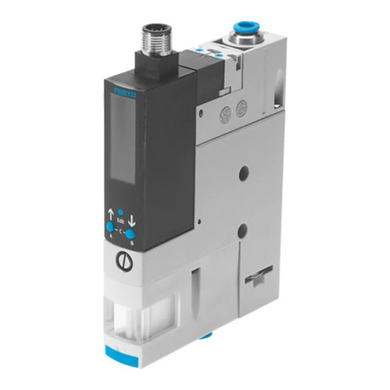
5 Exhaust port / silencer (3) 12 Electrical connection 6 Vacuum connection (6) 13 Size OVEM-...-C 7 Housing with mounting holes Fig. 1 Operating elements and connections Filter housing with display window only with OVEM-...-B/-BN Festo — OVEM — 2019-03g... -
Page 8: Product Variants
QS push-in fittings (-B-PL/-C-PL) prepared for common supply manifold, vacuum and exhaust port with QS push-in fittings inch (-BN-PL) prepared for common supply manifold, vacuum port with QS push-in fittings, exhaust port with open silencer (-B-PO/-C-PO) Festo — OVEM — 2019-03g... - Page 9 2 switching outputs NPN 1 switching output PNP, 1 analogue output 0 10 V … 1 switching output PNP, 1 analogue output 4 20 mA … Alternative vacuum display bar (-B), InHg (-BN) InH20 InHg Tab. 3 Overview of variants Festo — OVEM — 2019-03g...
-
Page 10: Display Components
10 Segment bar left: graphic display of the cur- rent pressure value related to the maximum measured value of the measuring range Fig. 2 LCD display and operating keys Symbol Description Threshold value comparator selected "[SP]" Switching point Festo — OVEM — 2019-03g... - Page 11 Segment L17 + "[A]" illuminated and Minimum pressure value display "[min]" flashing Segment L17 + "[A]" illuminated and Maximum pressure value display "[max]" flashing Segment L18 + "[B]" are on and "[msec]" + Duration of ejector pulse "[_|¯¯|_]" are flashing Festo — OVEM — 2019-03g...
- Page 12 Ejector pulse solenoid valve (Eject) switched Tab. 5 OVEM-...-2P/-2N/PU/PI: additional displays of segment bars – Examples Display Description Segment L10 is illuminated Vacuum solenoid valve is switched. Festo — OVEM — 2019-03g...
- Page 13 Setting of air-saving function (EDIT "<ON>" - "[optional]" flashing mode) "<ON>": air-saving function active "<OFF>": air-saving function not active Segments L1, L2, L5, L6 on and Setting the security code (1...9999) "[Lock]" flashing <OFF>: security code is not active Festo — OVEM — 2019-03g...
-
Page 14: Function
The switching outputs can be configured via the switching functions. The switching logic of the switch- ing outputs can be configured as normally open (NO) or normally closed (NC). The switching mode of the switching outputs can be set as threshold value or window comparator. Festo — OVEM — 2019-03g... - Page 15 Analogue output 0 10 V … vacuum Switching output negative Switching output negative 1 switching input negative switching pressure sensor switching pressure sensor switching output A output B or diagnostic mes- sage channel Tab. 10 Switching output and switching input variants Festo — OVEM — 2019-03g...
-
Page 16: Valve Controller
(ejector) DI2. Depending on the input signal, the vacuum solenoid valve or the ejector pulse solenoid valve is controlled. Festo — OVEM — 2019-03g... -
Page 17: Air Saving Function
Duration of ejector pulse (ejection) DI2 (only OVEM-...-1PD) Switching position of vacuum solenoid valve Fig. 3 Valve control switching behaviour 5.2.3 Air saving function The air saving function reduces air consumption during the evacuation phase. Festo — OVEM — 2019-03g... -
Page 18: Optimisation Of The Transport Time
Monitoring of process parameters (pressure value at the vacuum connection, switching points, switching outputs and switching inputs, evacuation time t , air supply time t and critical limits) – Diagnostic messages è 11.1 Diagnostic levels – Fault detection è 11 Error messages and fault clearance Festo — OVEM — 2019-03g... -
Page 19: Measured Variables
SP1 of the switching output is reached. The air supply time t is measured from the start of air supply to the time at which the pressure value (vacuum) falls below −50 mbar. Festo — OVEM — 2019-03g... -
Page 20: Teach Function (Teach-In)
After the start of the teach-in, time t and t are measured at every cycle. The times are averaged over multiple cycle times. At the end of the teach-in, a function reserve of 100% is added to the averaged values. Festo — OVEM — 2019-03g... -
Page 21: Operating Statuses And Menu Structure
Symbol on the display flashes (here display segment switching output Out A) Input blocked / not blocked press individual pushbutton (here A-pushbutton) Press A or B-pushbutton, set value Press pushbutton simultaneously (here: B-key and EDIT button) Press EDIT button Branching Error display Festo — OVEM — 2019-03g... - Page 22 Basic status after the operating voltage is applied – Display of the current measured value (relative pressure) – Display of the signal statuses of the solenoid valves – Display of the selected inputs and outputs Festo — OVEM — 2019-03g...
- Page 23 Display and deletion of the minimum and maximum pressure values – Display and deletion of the minimum and maximum evacuation and air supply time – Display of diagnostic messages 1 Submenu only available with OVEM-...-2P/-2N/-PU/-PI Fig. 7 Menu structure for SHOW mode Festo — OVEM — 2019-03g...
- Page 24 Product overview EDIT mode – Setting of parameters – Operation of the electrical manual override (FORC) 1 Submenu only available for OVEM-...-CE/-OE Fig. 8 EDIT mode menu structure Festo — OVEM — 2019-03g...
-
Page 25: Assembly
• Install the vacuum generator so that it cannot be heated above the maximum permissible operat- ing temperature (plan for possible convection). • Install the vacuum generator so that the exhaust can flow without hindrance. Festo — OVEM — 2019-03g... - Page 26 Tab. 12 Size and tightening torque of the screws with direct mounting on the side Fig. 11 Direct mounting on the back Variant Screw Tightening torque OVEM-...-05/-07/-10/-14/-20-...-B/-BN max. 0.8 Nm OVEM-...-20/-30-...-C max. 0.8 Nm Tab. 13 Size and tightening torque of the screws with direct mounting on the back Festo — OVEM — 2019-03g...
- Page 27 2. Attach Hang OVEM with H-rail mounting in the H-rail and press in the direction of the arrow. 3. Secure to the H-rail with screw 2. Mounting via mounting bracket Type of mounting permissible only for sizes OVEM-...-05/-07/-10/-14/-20-...-B/-BN Accessories for mounting bracket è www.festo.com/catalogue Fig. 13 Mounting with mounting bracket Festo — OVEM — 2019-03g...
-
Page 28: Installation
Mounting is possible on a common supply manifold with a maximum of 8 places for OVEM-...-B/-BN. Mounting is possible on a common supply manifold with a maximum of 4 places for OVEM-...-C. Assembly instructions for common supply manifold OABM-P è www.festo.com/sp Installation... -
Page 29: Electrical Installation
Do not seal exhaust port. – OVEM-...-07/-10/-14/-20/-30: If necessary, lengthen silencers with a silencer extension è www.festo.com/catalogue. – Recommendation: Use type PUN tubes è www.festo.com/catalogue. Electrical installation WARNING! Risk of injury due to electric shock. • For the electrical power supply, use only PELV circuits in accordance with IEC 60204-1/EN 60204-1 (Protective Extra-Low Voltage, PELV). - Page 30 (ejection) (PNP) grey (GY) digital switching input (suction) 1) When using the connecting cable as per accessories Tab. 19 Pin allocation OVEM-...-1PD Circuit diagrams OVEM-...-2P OVEM-...-2N OVEM-...-PU OVEM-...-PI OVEM-...-1PD Tab. 20 Circuit diagrams for vacuum generator Festo — OVEM — 2019-03g...
-
Page 31: Commissioning
Changing the operating pressure changes the power of the negative pressure at the vacuum connec- tion. This adjusts the vacuum at the suction gripper. Functions and parameters can be specified: – manually at the device – by teach-in Set the intensity of the ejector pulse Fig. 14 Festo — OVEM — 2019-03g... -
Page 32: Operation And Use
When large suction grippers are used, a vacuum independent of the device may be built up for physic- al reasons. The result is that the workpiece may not be released from the suction gripper, even if the ejector pulse is set to a sufficiently long duration. Festo — OVEM — 2019-03g... -
Page 33: Configuring Switching Outputs
Out A as an example. Requirements – RUN mode is active. – Switching output Out B is defined as switching output In A1. – Security code is not active. Festo — OVEM — 2019-03g... -
Page 34: Set Diagnostic Message Channel
Ä [B] flashes. 3. Press the EDIT button. Ä If Out B is defined as switching output, <InA1> is displayed. 4. Set the diagnostic message channel (dI 1 or dI 2) using the A or B pushbutton. Festo — OVEM — 2019-03g... -
Page 35: Teach-In Switching Points
The hysteresis is adjusted to the teach-in values. Set hysteresis (è 9.2 Configuring switching outputs). Recommendation: check the teach-in values in a test run. Deleting minimum or maximum pressure value Requirements – RUN mode is active. Festo — OVEM — 2019-03g... -
Page 36: Setting Critical Limits For The Evacuation And Air Supply Times
[OFF]: air supply time monitoring is not active. 8. Press the EDIT button. Ä RUN mode is active. Teaching evacuation and air supply time Requirements – RUN mode is active. – Security code is not active. – Switching function is set. Festo — OVEM — 2019-03g... -
Page 37: Displaying Evacuation And Air Supply Times
Ä Maximum air supply time is displayed. 7. Press A and B pushbuttons simultaneously. Ä RUN mode is active. 9.10 Deleting evacuation and air supply times Requirements – SHOW mode is active. – Minimum evacuation time is displayed. Festo — OVEM — 2019-03g... -
Page 38: Electrical Manual Override
9.12 Mechanical manual override Both solenoid valves can be manually switched with the manual override. Fig. 15 1. Press in the plunger of the manual override with a blunt pin. Ä The solenoid valve switches. Festo — OVEM — 2019-03g... -
Page 39: Activating Security Code
3. Switch the air saving function on or off using the A or B pushbutton. – [ON]: air saving function active. – [OFF]: air-saving function not active. 4. Press and hold the EDIT button for 3 seconds. Ä RUN mode is active. Festo — OVEM — 2019-03g... -
Page 40: Restore Factory Settings
Tab. 21 Factory settings Maintenance and care Clean device 1. Switch off energy sources: – Operating voltage – Compressed air 2. Clean device with non-abrasive cleaning agents. 3. Check air filter through the display window for dirt. Festo — OVEM — 2019-03g... -
Page 41: Error Messages And Fault Clearance
(NO) or a normally closed contact (NC). 11.1 Diagnostic levels There are 4 diagnostic levels. The backlight of the display shows red for messages of diagnostic levels 1 to 3. Festo — OVEM — 2019-03g... -
Page 42: Error Messages And Error Codes
Solenoid valve does not switch or does several times. not switch correctly. – Check supply voltage. Plunger does not move; current – Replace device. through solenoid coil is too low; short circuit in solenoid coil Festo — OVEM — 2019-03g... -
Page 43: Malfunctions
Workpiece not released from suc- device-independent vacuum – Activate ejector tion gripper between workpiece and suction pulse when lifting gripper, ejector pulse not activated the suction gripper. or not sufficiently dimensioned – Increase duration and intensity of ejector pulse. Festo — OVEM — 2019-03g... - Page 44 11.1 Diagnostic è simultaneously levels Display flashes and error code Diagnostic level 3 active – 11.1 Diagnostic è appears levels "[Option]" flashes Air-save function deactivated – Check for leakage. because outside the critical limit Tab. 24 Malfunctions Festo — OVEM — 2019-03g...
-
Page 45: Disassembly
[bar] … OVEM-...-QS/-GN/-PL Operating pressure [bar] … OVEM-...-QO/-GO/-PO Pressure measuring [bar] – … range Overload pressure at [bar] £ vacuum port Ready-state delay [ms] £ Dead time (evacuation [ms] < £ £ £ and ejection) Festo — OVEM — 2019-03g... - Page 46 Insulation voltage Surge resistance [kV] Max. current consumption OVEM-...-2P/-2N [mA] OVEM-...-PI/-PU [mA] OVEM-...-1PD [mA] Accuracy [% FS] ± Hysteresis [% FS] ± Short circuit current rating Reverse polarity pro- For all electrical connections tection Festo — OVEM — 2019-03g...
- Page 47 Protection class Degree of protection IP 65 Relative humidity … Interference emission as per EN 61000-6-4 Immunity to interfer- as per EN 61000-6-2 ence Maximum permissible signal line length Materials Information on seal HNBR materials Festo — OVEM — 2019-03g...
- Page 48 -14/-20-B/- -20/-30-C Information on housing Die-cast aluminium, PA reinforced Wrought alu- materials minium alloy Information on plug Nickel-plated brass housing material 1) degree of protection has not been evaluated by UL Tab. 25 Technical data Festo — OVEM — 2019-03g...
- Page 50 Copyright: Festo AG & Co. KG 73734 Esslingen Ruiter Straße 82 Germany Phone: +49 711 347-0 Fax: +49 711 347-2144 Reproduction, distribution or sale of this document or communic- e-mail: ation of its contents to others without express authorization is service_international@festo.com...
Need help?
Do you have a question about the OVEM Series and is the answer not in the manual?
Questions and answers