
Related Manuals for Festo OVEM Series


Summary of Contents for Festo OVEM Series
- Page 1 OVEM-...-LK Vacuum generator Operating instructions 8140363 8140363 2020-07e [8140365]...
- Page 2 Translation of the original instructions Festo — OVEM-...-LK — 2020-07e...
-
Page 3: Table Of Contents
Electrical manual override.................... 29 Activating the security code..................29 Restoring factory settings..................... 29 Maintenance and care....................30 Fault clearance......................31 11.1 Status messages......................31 11.2 Diagnostic levels......................31 11.3 Error messages and error codes................... 32 11.4 Malfunctions......................... 33 Festo — OVEM-...-LK — 2020-07e... - Page 4 14.1.1 General information, IO-Link.................. 38 14.1.2 Identification of parameters................... 38 14.1.3 Process data......................39 14.1.4 Smart Sensor profile parameters................40 14.1.5 Device parameters....................44 14.1.6 Observation parameters..................45 14.1.7 Diagnostics......................47 14.1.8 Device commands....................48 Festo — OVEM-...-LK — 2020-07e...
-
Page 5: About This Document
About this document About this document Applicable documents All available documents for the product è www.festo.com/sp. Document Product Contents Instruction manual Manifold rail OABM-P Assembly Tab. 1 Applicable documents Safety Safety instructions – The product may only be used in its original status without unauthorised modifications. -
Page 6: Further Information
IEC/EN/UL/CSA 60950-1 or IEC/EN/UL/CSA 62368-1 or a Class 2 circuit in accordance to NEC or CEC. Further information – Accessories è www.festo.com/catalogue. – Spare parts è www.festo.com/spareparts. Service Contact your regional Festo contact person if you have technical questions è www.festo.com. Product overview Festo — OVEM-...-LK — 2020-07e... -
Page 7: Product Design
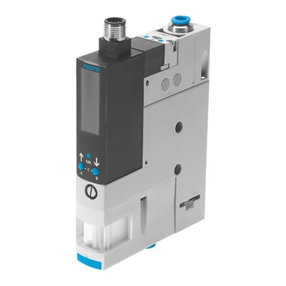
7 Housing with mounting holes Fig. 1 Operating elements and connections Filter housing with inspection window only with OVEM-...-B 5.1.1 Product variants Product variant Code Meaning Vacuum generator OVEM Vacuum generator with solenoid valve ON/OFF and electric manual override Festo — OVEM-...-LK — 2020-07e... - Page 8 N/C, normally closed (no vacuum generation) with ejector pulse -CPE N/C, normally closed (no vacuum generation) with power ejector pulse Electrical connection M12 plug (5-pin) Vacuum sensor IO-Link Alternative vacuum display InHg (indication on display) Tab. 3 Overview of variants Festo — OVEM-...-LK — 2020-07e...
-
Page 9: Display Components
Fig. 2 LCD display and operating buttons Symbol Description C flashes: IO-Link mode active Threshold value comparator selected "[SP]" Switching point Window comparator selected Festo — OVEM-...-LK — 2020-07e... - Page 10 Segment L17 + "[A]" lit and "[min]" flashing Minimum pressure value display Segment L17 + "[A]" lit and "[max]" flash- Maximum pressure value display Segment L18 + "[B]" lit and "[msec]" + Duration of ejector pulse "[_|¯¯|_]" flashing Festo — OVEM-...-LK — 2020-07e...
-
Page 11: Function
2 binary data channels for programming switching functions and switching characteristics. SIO mode: local configuration via the operating buttons. In the SIO mode, OVEM has the function of a 2P variant (1 switching input, 2 switching outputs). Festo — OVEM-...-LK — 2020-07e... -
Page 12: Switching Functions
1) TP1 = minimum pressure value, TP2 = maximum pressure value, independent of the teach-in sequence Tab. 7 Window comparator: setting of switching points SP1, SP2 and hysteresis HY 5.2.2 Valve control The vacuum solenoid valve or the ejector pulse solenoid valve is controlled as defined by the input signal. Festo — OVEM-...-LK — 2020-07e... - Page 13 Destruction of the vacuum sensor due to overpressure (-CPE/-OPE) The exhaust duct is sealed tightly during the power ejector pulse. This can cause overpressure at the vacuum port and destroy the vacuum sensor. • Use power ejector pulse only in open vacuum systems. Festo — OVEM-...-LK — 2020-07e...
-
Page 14: Air Saving Function
Switching position of vacuum solenoid Vacuum port (2) valve Duration of ejector pulse Fig. 3 Valve control switching characteristics 5.2.3 Air saving function The air saving function reduces air consumption during the evacuation phase. Festo — OVEM-...-LK — 2020-07e... -
Page 15: Monitoring And Diagnostics
The monitoring functions are activated at the factory (except monitoring of the evacuation and pres- surisation times). The time monitoring can be activated through setting of the critical limit values SP1 (evacuation time) and SP2 (pressurisation time) in BDC4 è Tab. 26 Smart Sensor profile parameters Festo — OVEM-...-LK — 2020-07e... -
Page 16: Measured Variables
SP1 by BDC1 or BDC2. The pressurisation time t is measured from the start of pressurisation to the time at which the pres- sure value (vacuum) falls below -50 mbar. Festo — OVEM-...-LK — 2020-07e... -
Page 17: Teach Function
Simplified Teach commands “BDCx Start” (Start Teach), “BDCx Stop” (Stop Teach) can be used independently of the switching function. The sequence of the teach points need not be con- sidered. – For all commands, the desired channel must first be selected. Festo — OVEM-...-LK — 2020-07e... -
Page 18: Data Storage
Transfer of block parameters by start and end commands è Tab. 32 Command code – Parameter changes (e.g. through teach-in) are blocked during the transfer. – In case of an invalid parameter set, the changed parameters are discarded and the previous para- meter set is reactivated. Festo — OVEM-...-LK — 2020-07e... -
Page 19: Operating Statuses And Menu Structure
Basic status after the operating voltage is applied – Display of the current measured value (relative pressure) – Display of the signal statuses of the solenoid valves – Display of the selected inputs and outputs Festo — OVEM-...-LK — 2020-07e... - Page 20 – Display and delete minimum and maximum pressure values – Display and delete minimum and maximum evacuation and pressurisation time – Display of diagnostic messages Fig. 7 Menu structure for SHOW mode in SIO mode Festo — OVEM-...-LK — 2020-07e...
- Page 21 Product overview EDIT mode – Setting of parameters – Operation of the electrical manual override (FORC) Fig. 8 Menu structure for EDIT mode in SIO mode Festo — OVEM-...-LK — 2020-07e...
-
Page 22: Assembly
Fig. 9 Menu structure for TEACH-IN mode in SIO mode Assembly An unfavourable mounting position may impair the function of the product. • Avoid condensate accumulation in the device through a suitable mounting position. • Exhaust air must be able to flow out unhindered. Festo — OVEM-...-LK — 2020-07e... - Page 23 Tab. 9 Size and tightening torque of the screws for direct mounting on the side Fig. 11 Direct mounting on the back Variant Screw Tightening torque OVEM-...-05/-07/-10/-14/-20-...-B max. 0.8 Nm OVEM-...-20/-30-...-C max. 0.8 Nm Tab. 10 Size and tightening torque of the screws with direct mounting on the back Festo — OVEM-...-LK — 2020-07e...
- Page 24 2. Attach OVEM with H-rail mounting to the H-rail and press in the direction of the arrow. 3. Secure to the H-rail with screw 2. Mounting with mounting bracket Type of mounting permissible only for sizes OVEM-...-05/-07/-10/-14/-20-...-B Accessories for mounting bracket è www.festo.com/catalogue Fig. 13 Mounting with mounting bracket Festo — OVEM-...-LK — 2020-07e...
-
Page 25: Installation
OVEM-...-B: Mounting is possible on a common supply manifold with a maximum of 8 places. OVEM-...-C: Mounting is possible on a common supply manifold with a maximum of 4 places. Assembly instructions for common supply manifold OABM-P è www.festo.com/sp Installation Pneumatic installation... -
Page 26: Electrical Installation
Do not seal exhaust port. – OVEM-...-07/-10/-14/-20/-30: If necessary, lengthen silencers with a silencer extension è www.festo.com/catalogue. – Recommendation: Use type PUN tubes è www.festo.com/catalogue. Electrical installation WARNING! Risk of injury due to electric shock. • For the electrical power supply, use only PELV circuits in accordance with IEC 60204-1/EN 60204-1 (Protective Extra-Low Voltage, PELV). -
Page 27: Commissioning
Changing the operating pressure changes the power of the negative pressure at the vacuum port. This allows the vacuum to be adjusted. Functions and parameters can be specified: – manually at the device è EDIT mode – by teach-in è TEACH mode – by teach-in è TEACH mode Festo — OVEM-...-LK — 2020-07e... -
Page 28: Setting The Intensity Of The Ejector Pulse
Parameter description IO-Link mode è 14.1 Technical data for parameterisation interface – Meaning of the displays è 5.1.2 Display components – Menu structure in SIO mode è TEACH mode Mechanical manual override Both solenoid valves can be manually switched with the manual override. Festo — OVEM-...-LK — 2020-07e... -
Page 29: Electrical Manual Override
2. Press and hold the A pushbutton + B pushbutton + EDIT button simultaneously. 3. Switch on the operating voltage. 4. Release A pushbutton + B pushbutton + EDIT button. Ä LCD display shows [CLEAR] The factory settings are restored. Festo — OVEM-...-LK — 2020-07e... -
Page 30: Maintenance And Care
Operating voltage – Compressed air 2. Clean device with non-abrasive cleaning agents. 3. Check air filter through the display window for dirt. Replace air filter The air filter cannot be replaced in the vacuum generator OVEM-...-20/-30-C Festo — OVEM-...-LK — 2020-07e... -
Page 31: Fault Clearance
Outside the specification Error Malfunction Tab. 16 Status messages for IO-Link diagnostics 11.2 Diagnostic levels There are 4 diagnostic levels. The backlight of the display shows red for messages of diagnostic levels 1 to 3. Festo — OVEM-...-LK — 2020-07e... -
Page 32: Error Messages And Error Codes
Press mechanical does not switch or does manual override sever- not switch correctly al times – Check supply voltage Er33 0x1821 Ejector pulse solenoid – Replace device valve does not switch or does not switch correctly Festo — OVEM-...-LK — 2020-07e... -
Page 33: Malfunctions
– Increase duration and intensity or sufficiently dimensioned of ejector pulse. Tubing dimensioned incorrectly – Replace tubing (tubing dimen- sions 7.1 Pneumatic installation). è Festo — OVEM-...-LK — 2020-07e... -
Page 34: Disassembly
Diagnostic level 3 active – 11.2 Diagnostic levels è error code appears "[Option]" flashing Teach-in faulty – Set hysteresis larger, repeat teach-in Tab. 19 Malfunctions Disassembly 1. Switch off energy sources: – Operating voltage – Compressed air Festo — OVEM-...-LK — 2020-07e... -
Page 35: Disposal
Dead time (evacuation [ms] £ £ and ejection) Electronics Nominal operating [V DC] 15 % ± voltage Max. output current [mA] (per switching output) Voltage drop (for all £ switching outputs) No-load supply current [mA] < Festo — OVEM-...-LK — 2020-07e... - Page 36 Setting range threshold [bar] 0.999 – … values Hysteresis setting [bar] – … range Setting range ejector [ms] 9999 9999 … … pulse duration Environment Ambient temperature [°C] … Temperature of medi- [°C] … Contamination level Festo — OVEM-...-LK — 2020-07e...
-
Page 37: Technical Data For Parameterisation Interface
1) Degree of protection has not been evaluated by UL Tab. 20 Technical data 14.1 Technical data for parameterisation interface Associated device description file (IODD) è www.festo.com/sp. For detailed information on the IO- Link specification and for the Smart Sensor profile è www.io-link.com Festo — OVEM-...-LK — 2020-07e... -
Page 38: General Information, Io-Link
0x0A DeviceID2 0x00 0x0B DeviceID3 (LSB) Device variant OVEM- … … Device variant OVEM- … … Device variant OVEM- … … Device variant OVEM- … … Device variant OVEM-…-H-…-OPE Device variant OVEM-…-L-…-OPE Device variant OVEM-…-H-…-CPE Festo — OVEM-...-LK — 2020-07e... -
Page 39: Process Data
2) Allocation of the BDC is dependent on the parameter “Air saving function”: Air-save ON = BDC1, Air-save OFF = BDC2 3) Current pressure value) standardised and scaled to 14 bit. Formula: p2 = pressure value*(1000 mbar/16383) Tab. 24 Process data IN Festo — OVEM-...-LK — 2020-07e... -
Page 40: Smart Sensor Profile Parameters
0x003A 0 Teach-In channel Default value; BDC1 with activated air saving function (air-save = ON); BDC2 with deactivated air saving function (air-save = OFF) BDC1 - Out A (air save) BDC2 (Out A) BDC3 (Out B) Festo — OVEM-...-LK — 2020-07e... - Page 41 … OVEM- -L: 6553 (-0.4 bar) … OVEM- -H: 11468 … (-0.7 bar) Setpoint SP2 Upper switching point default value: 0 0x003D Switchpoint logic Switching point logic N/O (default) Switching point logic N/C Switchpoint Switching point mode Festo — OVEM-...-LK — 2020-07e...
- Page 42 OVEM- -H: 11468 … (-0.5 bar) Setpoint SP2 16383 Upper switching point … -1 bar) default values: … OVEM- -L: 6717 … (-0.41 bar) OVEM- -H: 15892 … (-0.71 bar) 0x4001 1 Switchpoint logic Switching point logic N/O (default) Festo — OVEM-...-LK — 2020-07e...
- Page 43 3) Time = 2.5 ms * Value 4) Value = 128: vendor specific. Five measurements are recorded; if the limit is exceeded 3 times, an event is created as a warning Tab. 26 Smart Sensor profile parameters Festo — OVEM-...-LK — 2020-07e...
-
Page 44: Device Parameters
Switching point logic of pin 2 – N/O point logic (default) Switching point logic of pin 2 – N/C 0x01EA 0 Lock Code Local parameterisation is enabled (default) Local parameterisation is blocked by ³ security code (max. 9999) Festo — OVEM-...-LK — 2020-07e... -
Page 45: Observation Parameters
… output data; default: 0 Process data out- Vacuum solenoid valve not put BCS1 switched Vacuum solenoid valve switched Process data out- Ejector pulse solenoid valve not put BCS2 switched Ejector pulse solenoid valve switched Festo — OVEM-...-LK — 2020-07e... - Page 46 2) With air saving function activated (=ON), the status of the BDC1 is output With air-saving function deactivated (=OFF), the status of the BDC2 is output 3) Time = 2.5 ms * Value Tab. 28 Observation parameters Festo — OVEM-...-LK — 2020-07e...
-
Page 47: Diagnostics
Overload at plug, pin 2 Evacuation solen- 0x1820 Vacuum solenoid valve faulty oid failure Ventilation solen- 0x1821 Ejector pulse solenoid valve faulty oid failure Evacuation time 0x1822 Evacuation time t exceeded 3 times overrun out of 5 measurements Festo — OVEM-...-LK — 2020-07e... -
Page 48: Device Commands
Subindex Name Description Info 0x0002 System System command, is sent with a command code Command Tab. 32 Command code è 1) W = write Tab. 31 System commands Command Name Description code – 0x00 Reserved Festo — OVEM-...-LK — 2020-07e... - Page 49 Cancel all teach-in sequences 0x80 Device Reset Warm start of the device, reset of runtime para- meters 0x82 Restore factory settings Reset the configuration and the parameters to the original condition (default values) Tab. 32 Command code Festo — OVEM-...-LK — 2020-07e...
- Page 50 Copyright: Festo SE & Co. KG 73734 Esslingen Ruiter Straße 82 Germany Phone: +49 711 347-0 Internet: www.festo.com © 2020 all rights reserved to Festo SE & Co. KG...
Need help?
Do you have a question about the OVEM Series and is the answer not in the manual?
Questions and answers