Festo OVEM LK Series Instructions & Operating
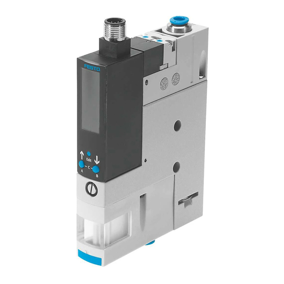
Vacuum generator
Hide thumbs
Also See for OVEM LK Series:
- Operating instructions manual (88 pages) ,
- Operating instructions manual (50 pages)


Need help?
Do you have a question about the OVEM LK Series and is the answer not in the manual?
Questions and answers