progressive automations FLT-05 User Manual
Hide thumbs
Also See for FLT-05:
- Assembly instructions manual (10 pages) ,
- User manual (9 pages) ,
- User manual (17 pages)

Subscribe to Our Youtube Channel
Related Manuals for progressive automations FLT-05

Summary of Contents for progressive automations FLT-05
-
Page 1: Table Of Contents
FLT-05 User Manual Contents Caution Specifications Dimensional Drawing Components Assembly Operation Reset Procedure Troubleshooting... -
Page 2: Caution
Caution Warning Ensure no obstacles are in the table lift's path. Ensure the Pinch Point tabletop is not touching any walls. Ensure all cords are Keep hands and appropriate length to accommodate the change in height. fingers clear. Keep children away from electric height-adjustable table lifts, control units, and handsets. There is a risk of injury and electric shock. -
Page 3: Specifications
Specifications Input Voltage 120VAC, 60 Hz Output Voltage 24VDC Stroke (movement) 25.5" 23.5” - 49” Height Range (without tabletop) Weight Capacity (load) 330 lbs (110 lbs per leg) No Load Speed 1.57"/s Full Load Speed 1.18"/s Duty Cycle 10% (2 minutes on, 18 minutes off) Operating Noise <... -
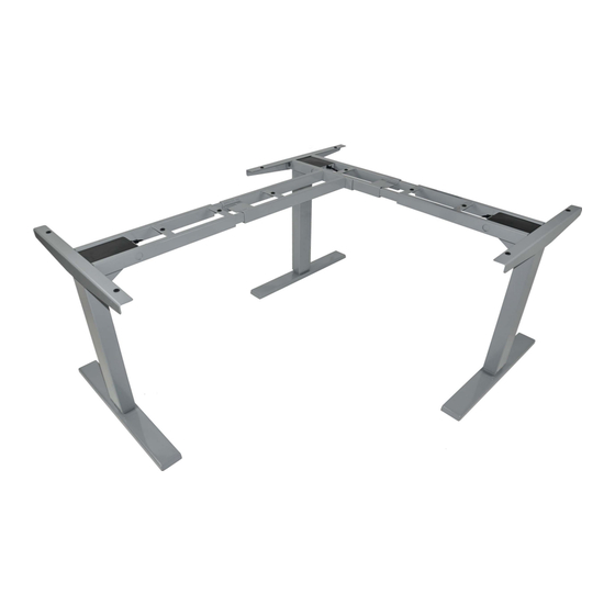
Page 4: Dimensional Drawing
Dimensional Drawing Maximum Width - 72.6" Minimum Width - 42.7" 1.7" 22.6" Extended - 49.0" 3.1" 2.0" Retracted - 23.5" 1.3" 27.6" 2.8" *Feet and column style may vary slightly... -
Page 5: Components
Components Tools 4mm Allen Wrench (included) Phillips Head Screwdriver Tape Measure and/or Power Drill Parts Parts List Description Rubber Block Frame 1 Frame 2 Side Bracket Frame 3 Foot Ceter Rail Caster Cable Clip ST5x16 Wood Screw ST5x20 Wood Screw M6x10 Machine Screw M6x14 Machine Screw Control Box... -
Page 6: Assembly
Assembly STEP 3 STEP 1 Place one of the Legs (9) into Frame 3 (5). Line up the The Frame 1 (2) should be placed on the side of the holes on the Leg (9) with the holes on Frame 3 (5). desk where you plan to mount the Control Box (15). - Page 7 Assembly STEP 6 STEP 8 Lock in the position of the Center Rails (7) using eight We recommend having at least two people for this M6x10 Machine Screws (13) as shown in the image below. step. Grab the base (the legs) of the assembled frame and turn it right side up.
-
Page 8: Operation
Operation Normal Operation Using the wired remote, press and hold the 'Up' button to raise the table lift. To lower the table lift, press and hold the 'Down' button. The 'Up' and 'Down' buttons are momentary controlled, when they are released, the table lift will stop immediately. -
Page 9: Troubleshooting
Troubleshooting Troubleshooting Guide Problem Possible Cause Corrective Action Low power mode Press any button on the remote and LED will activate. activated Remote LED is off. Disconnect and reconnect the RJ-45 remote connector. Ensure connection is Connection issue secure and cable is not damaged. Follow "Setting Limit Switches"...
Need help?
Do you have a question about the FLT-05 and is the answer not in the manual?
Questions and answers