
Related Manuals for H3C S5130-EI Series


Summary of Contents for H3C S5130-EI Series
-
Page 1: Installation Guide
H3C S5130-EI Switch Series Installation Guide New H3C Technologies Co., Ltd. http://www.h3c.com Document version: 6W106-20190409... - Page 2 The information in this document is subject to change without notice. All contents in this document, including statements, information, and recommendations, are believed to be accurate, but they are presented without warranty of any kind, express or implied. H3C shall not be liable for technical or editorial errors or omissions contained herein.
- Page 3 Preface H3C S5130-EI Switch Series Installation Guide describes the appearance, installation, power-on, maintenance, and troubleshooting of the H3C S5130-EI Switch Series. This preface includes the following topics about the documentation: • Audience. • Conventions. • Documentation feedback. Audience This documentation is intended for: •...
- Page 4 Symbols Convention Description An alert that calls attention to important information that if not understood or followed WARNING! can result in personal injury. An alert that calls attention to important information that if not understood or followed CAUTION: can result in data loss, data corruption, or damage to hardware or software. An alert that calls attention to essential information.
-
Page 5: Documentation Feedback
Documentation feedback You can e-mail your comments about product documentation to info@h3c.com. We appreciate your comments. -
Page 6: Table Of Contents
Contents Preparing for installation ···································································· 1 Safety recommendations ············································································································· 1 Examining the installation site ······································································································· 1 Temperature/humidity ·········································································································· 2 Cleanliness ························································································································ 2 EMI ·································································································································· 2 Laser safety ······················································································································· 3 Installation tools ························································································································· 3 ... - Page 7 Appendix A Chassis views and technical specifications ·························· 32 Chassis views ························································································································· 32 S5130-28S-EI ··················································································································· 32 S5130-28S-PWR-EI ··········································································································· 32 S5130-28S-HPWR-EI ········································································································· 33 S5130-28TP-EI ················································································································· 34 S5130-28TP-PWR-EI ········································································································· 34 S5130-52S-EI ··················································································································· 35 S5130-52S-PWR-EI ··········································································································· 36 ...
-
Page 8: Preparing For Installation
Preparing for installation The H3C S5130-EI Switch Series includes the following models: • S5130-28S-EI. • S5130-28S-PWR-EI. • S5130-28S-HPWR-EI. • S5130-28TP-EI. • S5130-28TP-PWR-EI. • S5130-52S-EI. • S5130-52S-PWR-EI. • S5130-52TP-EI. • S5130-52TP-PWR-EI. • S5130-28F-EI. • S5130-28PS-EI. Safety recommendations To avoid equipment damage or bodily injury, read the following safety recommendations before installation. -
Page 9: Temperature/Humidity
Temperature/humidity Maintain temperature and humidity in the equipment room as described in "Technical specifications." • Lasting high relative humidity can cause poor insulation, electricity leakage, mechanical property change of materials, and metal corrosion. • Lasting low relative humidity can cause washer contraction and ESD and bring problems including loose mounting screws and circuit failure. -
Page 10: Laser Safety
• Keep the switch far away from radio transmitting stations, radar stations, and high-frequency devices to make sure the EMI levels do not exceed the compliant range. • Use electromagnetic shielding when necessary. For example, use shielded interface cables. • To prevent signal ports from getting damaged by over-voltage or over-current caused by lightning strikes, only route interface cables indoors. -
Page 11: Installing The Switch
CAUTION: Keep the tamper-proof seal on a mounting screw on the chassis cover intact, and if you want to open the chassis, contact H3C for permission. Otherwise, H3C shall not be liable for any consequence. Figure 1 Hardware installation flow... -
Page 12: Attaching The Mounting Brackets To The Switch
Switch model Mounting brackets Views • S5130-28S-PWR-EI • S5130-28S-HPWR-EI • S5130-28TP-PWR-EI • S5130-52S-EI One pair of 1U four-hole Figure • mounting brackets S5130-52S-PWR-EI • S5130-52TP-EI • S5130-52TP-PWR-EI • S5130-28F-EI Figure 2 1U two-hole mounting bracket (2) Screw hole for attaching the bracket to the rack (1) Screw hole for attaching the bracket to the switch post Figure 3 1U four-hole mounting bracket... - Page 13 Figure 4 Attaching a two-hole mounting bracket to the front mounting position on an S5130-28S-EI switch Figure 5 Attaching a two-hole mounting bracket to the rear mounting position on an S5130-28S-EI switch Figure 6 Attaching a four-hole mounting bracket to the front mounting position on an S5130-28F-EI switch Figure 7 Attaching a four-hole mounting bracket to the rear mounting position on an S5130-28F-EI switch...
-
Page 14: Rack-Mounting The Switch
Rack-mounting the switch This task requires two people. To mount the switch in the rack: Wear an ESD wrist strap and make sure it makes good skin contact and is reliably grounded. Verify that the mounting brackets have been securely attached to the switch chassis. Install cage nuts (user-supplied) in the mounting holes in the rack posts. -
Page 15: Grounding The Switch
Figure 10 Mounting the switch on a workbench Grounding the switch WARNING! Correctly connecting the switch grounding cable is crucial to lightning protection and EMI protection. The power input end of the switch has a noise filter, whose central ground is directly connected to the chassis to form the chassis ground (commonly known as PGND). -
Page 16: Grounding The Switch With A Grounding Conductor Buried In The Earth Ground
Figure 11 Connecting the grounding cable to the grounding hole of the switch (1) Chassis rear panel (2) Grounding sign (3) Grounding hole (4) Ring terminal (5) Grounding cable (6) Grounding screw Connect the other end of the grounding cable to the grounding strip. a. -
Page 17: Installing And Removing A Power Module (S5130-28F-Ei Switch)
The dimensions of the angle iron must be at least 50 × 50 × 5 mm (1.97 × 1.97 × 0.20 in). The steel tube must be zinc-coated and its wall thickness must be at least 3.5 mm (0.14 in). Weld the yellow-green grounding cable to the angel iron or steel tube and treat the joint for corrosion protection. -
Page 18: Installing A Power Module
Installing a power module Wear an ESD wrist strap and make sure it makes good skin contact and is reliably grounded. Unpack the power module and verify that the power module model is as required. Remove the filler panel (if any) from the target slot. If you require only one power module, install it in power module slot 1 and make sure a filler panel is installed in power module slot 2. -
Page 19: Connecting The Power Cord
Figure 17 Removing a PSR150-A power module Connecting the power cord CAUTION: • Provide a circuit breaker for each power cord. • Before connecting a power cord, make sure the circuit breaker for the power cord is turned off. The S5130-28F-EI switch uses removable power modules: PSR150-A1, PSR150-A, or PSR150-D1. The other switch models use built-in power modules. -
Page 20: Connecting The Power Cord For An Ac Power Module
Switch model Available power source Connection procedure reference Connecting the power cord for an AC • S5130-28S-HPWR-EI AC power source power module • S5130-28TP-PWR-EI Connecting a DC power cord for the • S5130-52S-PWR-EI RPS (RPS1600-A) built-in DC power module (other switch •... -
Page 21: Connecting The Power Cord For A Psr150-D1 Power Module
• To connect to a –48 VDC power source, use the power cord shipped with the power module. • To connect to an H3C recommended RPS, use a power cord compatible with the RPS. • To connect a DC power cord to a –48 VDC power source, identify the positive (+) and negative (-) marks on the two wires of the power cord to avoid connection mistakes. -
Page 22: Connecting A Power Cord For The Built-In Dc Power Module (S5130-28Ps-Ei Switch)
Connecting a power cord for the built-in DC power module (S5130-28PS-EI switch) CAUTION: The S5130-28PS-EI switch has a built-in DC power module with an RPS receptacle exposed externally. • You can use only a RPS800-A power module to supply power to the DC power module. •... -
Page 23: Connecting A Dc Power Cord For The Built-In Dc Power Module (Other Switch Models Than S5130-28Ps-Ei
• No DC power cord is provided with the switch that has a built-in DC power module. To use a –48 VDC power source for power supply, purchase an H3C recommended DC power cord yourself. To use an RPS for power supply, purchase a power cord compatible with the RPS yourself. -
Page 24: Verifying The Installation
Figure 23 Connecting a DC power cord for the built-in DC power module (S5130-52S-EI) Verifying the installation After you complete the installation, verify the following items: • There is enough space for heat dissipation around the switch, and the rack or workbench is stable. -
Page 25: Accessing The Switch For The First Time
You can access other S5130-EI switch models only through the serial console port. No console cable or mini USB console cable is provided with the switch. Prepare yourself or purchase it from H3C. Figure 24 Connecting the serial console port to a PC... -
Page 26: Connecting The Mini Usb Console Cable (S5130-28Ps-Ei Switch)
Connect the mini USB connector to the mini USB console port on the switch. Click the following link, or copy it to the address bar on the browser to download the USB console driver. http://www.h3c.com.hk/Technical_Support___Documents/Software_Download/Other_Product /USB_Console/USB_Console/ Select a driver program according to the operating system you use: XR21V1410_XR21B1411_Windows_Ver1840_x86_Installer.EXE—32-bit operating... - Page 27 Figure 26 Device Driver Installation Wizard Click Continue Anyway if the following dialog box appears. Figure 27 Software Installation Click Finish.
-
Page 28: Setting Terminal Parameters
Figure 28 Completing the device driver installation wizard Setting terminal parameters To configure and manage the switch through the console port, you must run a terminal emulator program, HyperTerminal or PuTTY, on your configuration terminal. For more information about the terminal emulator programs, see the user guides for these programs. - Page 29 From the Boot ROM menu, you cannot use a 10G Ethernet port or SFP+ port to download files. After the startup completes, you can access the CLI to configure the switch. For more information about the configurations, see H3C S5130-EI Switch Series Configuration Guides and H3C S5130-EI Switch Series Command References.
-
Page 30: Setting Up An Irf Fabric
Setting up an IRF fabric You can use H3C IRF technology to connect and virtualize S5130-EI switches into a large virtual switch called an "IRF fabric" for flattened network topology, and high availability, scalability, and manageability. IRF fabric setup flowchart... -
Page 31: Planning Irf Fabric Setup
IRF fabric at the CLI of the master switch. IRF member switches automatically elect a master. You can affect the election result by assigning a high member priority to the intended master switch. For more information about master election, see H3C S5130-EI Switch Series IRF Configuration Guide. -
Page 32: Identifying Physical Irf Ports On The Member Switches
You connect the IRF member switches through IRF ports, the logical interfaces for the connections between IRF member switches. Each IRF member switch has two IRF ports: IRF-port 1 and IRF-port 2. To use an IRF port, you must bind at least one physical port to it. When connecting two neighboring IRF member switches, you must connect the physical ports of IRF-port 1 on one switch to the physical ports of IRF-port 2 on the other switch. - Page 33 As a best practice, use ring topology to connect the switches. The following describes cabling schemes in ring topology. Connecting the IRF member switches in one rack Use SFP+ DAC cables to connect the IRF member switches (9 switches in this example) in a rack as shown in Figure 32.
-
Page 34: Configuring Basic Irf Settings
• Execute the display irf configuration command to verify the basic IRF settings. For more information about configuring basic IRF settings, see H3C S5130-EI Switch Series IRF Configuration Guide. Connecting the physical IRF ports Use twisted pair cables, SFP+ DAC cables, or SFP+ transceiver modules and fibers to connect the IRF member switches as planned. -
Page 35: Verifying The Irf Fabric Setup
Create a Layer 3 interface, assign it an IP address, and make sure the IRF fabric and the remote network management station can reach each other. Use Telnet or SNMP to access the IRF fabric from the network management station. (See H3C S5130-EI Switch Series Fundamentals Configuration Guide.) Verify that you can manage all member switches as if they were one node. -
Page 36: Maintenance And Troubleshooting
Over-temperature can cause the power module to stop working and enter the protection state. If the problem persists, contact H3C Support. RPS DC input If the system status LED or RPS status LED is off, an RPS input failure has occurred. -
Page 37: Hot-Swappable Power Module Failure
Over-temperature can cause the power module to stop working and enter the protection state. f. If the problem persists, contact H3C Support. • If the system status LED is on but the RPS status LED is steady yellow, an AC input failure has occurred. -
Page 38: Configuration Terminal Problems
Parity—None. Stop bits—1. Flow control—None. Verify that the console cable is not faulty. If the problem persists, contact H3C support. Garbled display on the configuration terminal The configuration terminal displays garbled text. To resolve the problem: Verify that the following settings are configured for the terminal: Baud rate—9600. -
Page 39: Appendix A Chassis Views And Technical Specifications
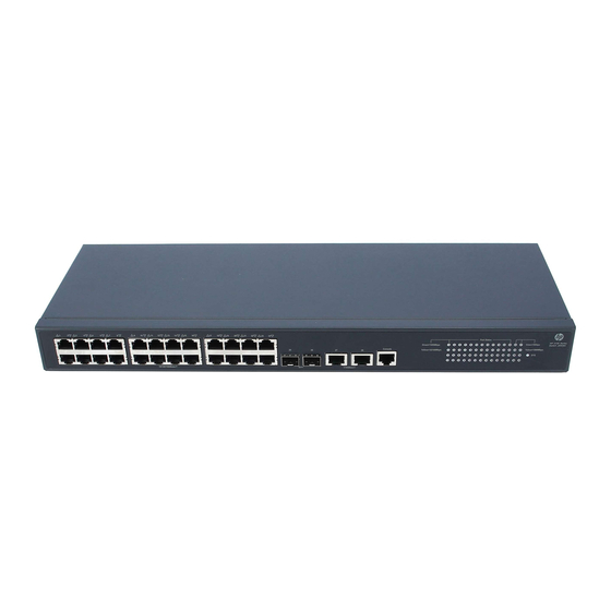
Appendix A Chassis views and technical specifications Chassis views S5130-28S-EI Figure 35 Front panel (1) 10/100/1000Base-T autosensing Ethernet port (2) SFP+ port (3) Console port (4) 10/100/1000Base-T autosensing Ethernet port LED (5) SFP+ port LED (6) System status LED (SYS) Figure 36 Rear panel (1) AC-input power receptacle (2) Grounding screw... -
Page 40: S5130-28S-Hpwr-Ei
Figure 38 Rear panel (1) AC-input power receptacle (2) Grounding screw S5130-28S-HPWR-EI Figure 39 Front panel (1) 10/100/1000Base-T autosensing Ethernet port (2) SFP+ port (3) Console port (4) Port LED mode switching button (5) Port mode LED (6) 10/100/1000Base-T autosensing Ethernet port LED (7) SFP+ port LED (8) System status LED (SYS) (9) RPS status LED (RPS) -
Page 41: S5130-28Tp-Ei
S5130-28TP-EI Figure 41 Front panel (1) 10/100/1000Base-T autosensing Ethernet port (2) SFP+ port (3) 1/10GBase-T autosensing Ethernet port (4) Console port (5) 10/100/1000Base-T autosensing Ethernet port LED (6) SFP+ port LED (7) System status LED (SYS) (8) 1/10GBase-T autosensing Ethernet port LED Figure 42 Rear panel (1) AC-input power receptacle (2) Grounding screw... -
Page 42: S5130-52S-Ei
Figure 44 Rear panel (1) AC-input power receptacle (2) RPS receptacle (3) Grounding screw S5130-52S-EI Figure 45 Front panel (1) 10/100/1000Base-T autosensing Ethernet port (2) 10/100/1000Base-T autosensing Ethernet port LED (3) Console port (4) SFP+ port LED (5) SFP+ port (6) System status LED (SYS) (7) RPS status LED (RPS) Figure 46 Rear panel... -
Page 43: S5130-52S-Pwr-Ei
S5130-52S-PWR-EI Figure 47 Front panel (1) 10/100/1000Base-T autosensing Ethernet port (2) 10/100/1000Base-T autosensing Ethernet port LED (3) Console port (4) SFP+ port (5) Port LED mode switching button (6) Port mode LED (7) System status LED (SYS) (8) RPS status LED (RPS) (9) SFP+ port LED Figure 48 Rear panel (1) Grounding screw... -
Page 44: S5130-52Tp-Pwr-Ei
Figure 50 Rear panel (1) AC-input power receptacle (2) RPS receptacle (3) Grounding screw S5130-52TP-PWR-EI Figure 51 Front panel (1) 10/100/1000Base-T autosensing Ethernet port (2) 10/100/1000Base-T autosensing Ethernet port LED (3) SFP+ port (4) Console port (5) Port LED mode switching button (6) Port mode LED (7) System status LED (SYS) (8) RPS status LED (RPS) -
Page 45: S5130-28F-Ei
S5130-28F-EI Figure 53 Front panel (1) 100/1000Base-X SFP port (2) 100/1000Base-X SFP port LED (3) 10/100/1000Base-T autosensing Ethernet port (4) 10/100/1000Base-T autosensing Ethernet port LED (5) SFP+ port (6) SFP+ port LED (7) Console port (8) System status LED (SYS) (9) Power module 1 status LED (PWR1) (10) Power module 2 status LED (PWR2) Figure 54 Rear panel... -
Page 46: S5130-28Ps-Ei
S5130-28PS-EI Figure 55 Front panel (1) 100/1000Base-X SFP port LED (2) 10/100/1000Base-T autosensing Ethernet port LED (3) System status LED (SYS) (4) RPS status LED (RPS) (5) 100/1000Base-X SFP port (6) 10/100/1000Base-T autosensing Ethernet port (7) Mini USB console port (8) Console port (9) SFP+ port (10) SFP+ port LED... - Page 47 Table an RPS an RPS (recommended (recommended H3C H3C models: RPS800-A models: RPS800-A or RPS1600-A) or RPS1600-A) Rated voltage: –48 Rated voltage: VDC to –60 VDC –48 VDC to –60 Max voltage: –36...
- Page 48 Table 9 Technical specifications for non-PoE switch models (2) Item S5130-28S-EI S5130-28TP-EI S5130-28PS-EI Dimensions 43.6 × 440 × 160 mm 43.6 × 440 × 160 mm 43.6 × 440 ×160 mm (1.72 × (H × W × D) (1.72 × 17.32 × 6.30 in) (1.72 ×...
- Page 49 Item S5130-28S-EI S5130-28TP-EI S5130-28PS-EI Operating 0°C to 45°C (32°F to 113°F) temperature Operating 5% to 95%, noncondensing humidity • UL60950-1 Fire • EN60950-1 resistance • IEC60950-1 compliance • GB4943.1 Table 10 Technical specifications for PoE switch models S5130-28S- S5130-28TP- S5130-28S-H S5130-52S-P S5130-52TP-P Item...
- Page 50 S5130-28S- S5130-28TP- S5130-28S-H S5130-52S-P S5130-52TP-P Item PWR-EI PWR-EI PWR-EI WR-EI WR-EI Minimum • • • • AC: 31 W AC: 30 W AC: 47 W AC: 43 W power 25 W • • • • DC: 20 W DC: 25 W DC: 43 W DC: 30 W consumption...
-
Page 51: Appendix B Frus
240 VDC • PSR150-A about the power input (supported modules, see only by the Max input voltage 180 VDC to 320 VDC H3C PSR150-A PSR150-A1 & PSR150-D power module) Series Power Max output power 150 W Modules User Manual. Rated input voltage –48 VDC to –60 VDC... -
Page 52: Appendix C Ports And Leds
Appendix C Ports and LEDs Ports Console port The S5130-28PS-EI switch provides a serial console port and a mini USB console port on the front panel. The other S5130-EI switch models provide only a serial console port. Table 12 Console port specifications Item Serial console port Mini USB console port... - Page 53 Modal Cable/Fiber Central band GE SFP transceiver type and wavelength Connector width transmission module and cable diameter (nm) (MHz* distance (µm) Single-mode, 10 km (6.21 miles) 9/125 Multi-mode, 500/40 SFP-GE-LX-SM1310-A 1310 550 m (1804.46 ft) 50/125 Multi-mode, 550 m (1804.46 ft) 62.5/125 SFP-GE-LX-SM1310- Single-mode,...
- Page 54 Table 14 10-GE SFP+ transceiver modules available for the SFP+ ports 10-GE SFP+ Central Fiber Modal transceiver wavelength Connector diameter bandwidth transmission module (nm) (µm) (MHz*km) distance 2000 300 m (984.3 ft) Multi-mode, 82 m (269.03 ft) 50/125 SFP-XG-SX-M 66 m (216.54 ft) M850-A 33 m (108.27 ft) Multi-mode,...
-
Page 55: Sfp Port
NOTE: • As a best practice, use only H3C SFP/SFP+ transceiver modules and cables for the SFP+ ports. • The H3C SFP/SFP+ transceiver modules and cables available for the SFP+ ports are subject to change over time. For the most recent list of SFP/SFP+ transceiver modules and cables, contact your H3C Support or marketing staff. -
Page 56: 1/10Gbase-T Autosensing Ethernet Port
1/10GBase-T autosensing Ethernet port The S5130-28TP-EI, S5130-28TP-PWR-EI, S5130-52TP-EI, and S5130-52TP-PWR-EI switches provide 1/10GBase-T autosensing Ethernet ports. Table 18 1/10GBase-T autosensing Ethernet port specifications Item Specification Connector type RJ-45 Interface attributes 1/10 Gbps, full duplex, MDI/MDI-X autosensing • 55 m (180.45 ft) over category-6 unshielded twisted pair cable Transmission medium and max •... -
Page 57: Power Module Status Led
Table 19 System status LED description LED mark Status Description Steady green The switch is operating correctly. Flashing green The switch is performing power-on self test (POST). Steady red The switch has failed POST. Flashing yellow Some ports have failed POST. The switch is powered off. -
Page 58: Sfp Port Status Led
Table 22 Description for the MODE LED LED mark Status Description Steady green The port status LEDs are showing port rates. MODE The port status LEDs are showing the status of PoE power Flashing green supply on the ports. SFP port status LED The S5130-28F-EI switch provides 24 SFP ports. -
Page 59: 10/100/1000Base-T Autosensing Ethernet Port Led
• The S5130-28S-EI, S5130-28TP-EI, S5130-28S-PWR-EI, S5130-28S-HPWR-EI, and S5130-28TP-PWR-EI switches provide two single-color LEDs for each SFP+ port to indicate its operating status. Table 25 Description for the two single-color LEDs for the SFP+ port Status Description A transceiver module is installed in the port. The port is Steady on operating at 10 Gbps, and a link is present on the port. - Page 60 Port mode Double-color Switch model LED (Mode) (green and yellow) Description status LED Status The port is operating at 1000 Mbps, Steady green and a link is present on the port. The port is sending or receiving data at Flashing green 1000 Mbps.
-
Page 61: 1/10Gbase-T Autosensing Ethernet Port Leds
Port mode Switch model LED (Mode) Status Description status The port is operating at 1000 Mbps, Steady on and a link is present on the port. Green The port is sending or receiving data Flashing at 1000 Mbps. No link is present on the port, or the port is not operating at 1000 Mbps. -
Page 62: Appendix D Cooling System
Status Description • No link is present on the port. • The port mode LED is operating in PoE mode (applicable to the PoE switch models.) • The S5130-28TP-EI and S5130-28TP-PWR-EI switches provide two single-color LEDs for each 1/10GBase-T autosensing Ethernet port to indicate its operating status. Table 29 Description for the two single-color LEDs for the 1/10GBase-T autosensing Ethernet port Status... - Page 63 Figure 58 Airflow through the chassis (1) Air inlet side (2) Air outlet side (3) Port side...
Need help?
Do you have a question about the S5130-EI Series and is the answer not in the manual?
Questions and answers