Table of Contents
Advertisement
Quick Links
Conforms to ANSI STD Z21.58-2015/ CSA 1.6-2015
OUTDOOR COOKING GAS APPLIANCE
Tools needed for assembly:
Phillips screwdriver, Pliers or Adjust-
able Wrench
DANGER
If you smell gas:
1. Shut off gas to the appliance.
2. Extinguish any open flames.
3. Open lid.
4. If odor continues, keep away from
the appliance and immediately call
your fire department.
Failure to follow these instructions could
result in fire or explosion which could
cause property damage, personal injury
or death.
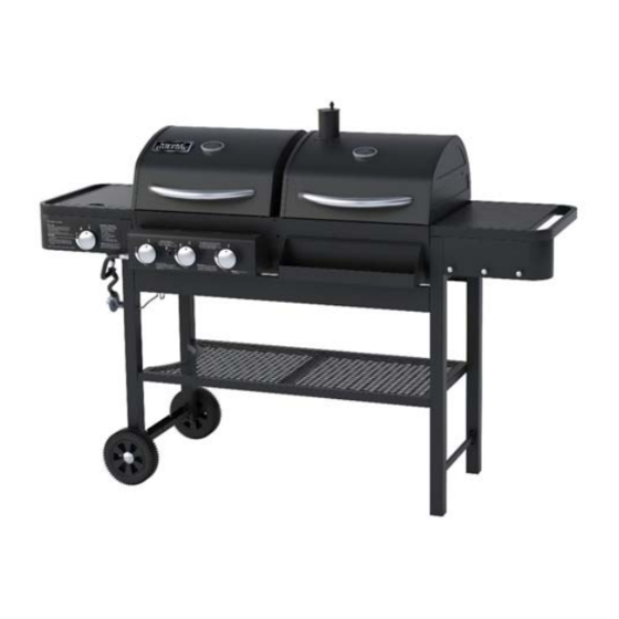
Grill
TC3718
DANGER
1. Never operate this appliance unat-
tended.
2. Never operate this appliance within
10 ft (3.0 m) of any structure, com-
bustible material or other gas cylin-
der.
3. Never operate this appliance within
25 ft (7.5 m) of any flammable liquid.
4. Do not fill cooking vessel beyond
maximum fill-line.
5. Never allow oil or grease to get hot-
ter than 400°F or 200°C. If the tem-
perature exceeds 400°F (200°C) or
if oil begins to smoke, immediately
turn the burner or gas supply OFF.
6. Heated liquids remain at scalding
temperatures long after the cooking
process. Never touch cooking appli-
ance until liquids have cooled to
115°F (45°C) or less.
7. If a fire should occur, keep away
from the appliance and immediately
call your fire department. Do not at-
tempt to extinguish an oil or grease
fire with water.
Failure to follow these instructions could
result in fire or explosion which could
cause property damage, personal injury
or death.
Advertisement
Table of Contents

Related Manuals for Smoke hollow TC3718


Summary of Contents for Smoke hollow TC3718
- Page 1 Grill TC3718 Conforms to ANSI STD Z21.58-2015/ CSA 1.6-2015 OUTDOOR COOKING GAS APPLIANCE DANGER 1. Never operate this appliance unat- tended. 2. Never operate this appliance within 10 ft (3.0 m) of any structure, com- bustible material or other gas cylin- der.
-
Page 2: Tc3718
WARNING WARNING The combustion of Propane gas can For Outdoor Use Only yield the formation of chemical com- (outside of any type of enclosure) pounds known in the state of Califor- nia,U.S.A., to cause birth defects, cancer,and other serious health mat- WARNING ters. -
Page 3: Tc3718
Read all safeguards and assembly instruc- In order to properly assemble your grill, tions before assembling and operating you will only need two tools: your grill. Phillips head screwdriver ● Pliers or adjustable wrench ● Before assembling your new grill, unpack (tools not included) all the parts from the box. -
Page 4: Tc3718
SAFETY WARNINGS 1. The installation of this grill must conform to local codes, or in the absence of local codes, with either the National Fuel Gas Code, ANSI Z223.1 / NFPA 54, Natural Gas and Propane Installation Code, CSA B149.1, or Propane Storage and Handling Code, B 149.2, or The Standard for recreational Vehicles, ANSI 119.2 / NFPA, and CSA Z240 RV Series, Recreational Vehicle Code, as Acceptable. -
Page 5: Tc3718
READ ALL SAFEGUARDS AND INSTRUCTIONS THOROUGHLY! YOUR SAFETY IS VERY IMPORTANT – FAILURE TO FOLLOW PROPER PROCEDURES AND SAFEGUARDS MAY RESULT IN PROPERTY DAMAGE, PERSONAL INJURY OR DEATH. DANGER DANGER Do not move the unit while it is being used. The GRILL is for outdoor use only! ●... -
Page 6: Tc3718
TC3718 Parts List Note: For assistance, including missing or damaged parts, call toll free - 866-475-5180 from 8:30 am - 4:30 pm Central Time, Monday - Friday... -
Page 7: Table Of Contents
TC3718 Parts List Item No. Quantity Description Part No. Side Burner Shelf Assembly TC3718-01 Side Burner Control Panel TC3718-02 Control Knob TC3718-03 Removable Grease Cup and Hook TC3718-04 Control Panel Assembly TC3718-05 Bottom Shelf TC3718-06 Left Rear Leg - Yellow Label #3... -
Page 8: Tc3718
TC3718 Parts List Hardware Pack Quantity Description M6x12 Combo Truss Head Bolts, Black Nickel Plated M6x15 Combo Truss Head Bolts, Black Nickel Plated M4x8 Combo Truss Head Bolts, Black Nickel Plated M4x15 Combo Truss Head Bolts, Black Nickel Plated M6x35 Combo Truss Head Bolts, Black Nickel Plated... -
Page 9: Tc3718
Assembly Note: Carefully cut the tape holding the carton together. Cut the carton so that it can lay flat on the ground to provide a clean surface for assembling your Grill. Remove the packing materials and all the parts from inside the Cabinet. After unpacking all the parts, check to make sure you HAVE all the parts. -
Page 10: Tc3718
Assembly Step 3: Assemble Cart Front/Rear Brack- Step 3 Locate: (2) Cart Front/Rear Brackets, (8) M6x12 bolts Procedure: Attach (2) Cart Front/Rear Brackets to four Legs using (8) M6x12 bolts as shown as Fig. 3. Fig. 3 Step 4: Assemble Bottom Shelf Step 4 Locate: Bottom Shelf, (4) M6x12 bolts Procedure: Attach the Bottom Shelf to four... -
Page 11: Tc3718
Assembly Step 6: Assemble Wheels Step 6 Locate: (2) Wheels, (2) Wheel Caps, (2) Axle Pins, (2) R clips Procedure: Slide (2) Axle Pins through the Wheels and then through the Left Front Leg #4 and Left Rear Leg #3. Then insert (1) R clip through the hole in each Axle Pin as shown as Fig. -
Page 12: Tc3718
Assembly Step 8: Attach Burners to Gas Grill Step 8 Locate: (1) Burner w/ Ignition Wire, (2) Burners w/o Ignition wire, (3) R clips Procedure: First, turn the grill upright. Tilt the burner tubes slightly and insert through the openings in the gas cabinet. Note: The Burner w/ Ignition Wire MUST be installed in the middle opening. -
Page 13: Tc3718
Assembly Step 10: Assemble Control Panel As- Step 10 sembly (Continued) Procedure: Place the Control Panel Assembly onto the Valves. You MUST make sure that the tip of the valve is completely INSIDE the end opening of the Burner Tube as shown as 10B. Attach the Control Panel Assembly to the Gas Cabinet using (4) M6x12 bolts from INSIDE of the cabinet as shown as Fig. -
Page 14: Tc3718
Assembly Step 11: Assemble Condiment Tray Step 11 Fig. 11A Locate: Condiment Tray, (4) M6x12 bolts Procedure: Attach the Condiment Tray to the Charcoal Cabinet using (4) M6x12 bolts from INSIDE of the cabinet as shown as Fig. 11A and Fig. 11B. Fig. -
Page 15: Tc3718
Assembly Step 13: Assemble Air Damper and Han- Step 13 dle Sleeve (Continued) Procedure: Assemble the Air Damper Handle Sleeve onto the Handle as shown as Fig. 13B. Fig. 13B Step 14 Step 14: Assemble Charcoal Tray Sup- porting Brackets Locate: (2) Charcoal Tray Supporting Brackets, (4) M6x12 bolts Procedure: Attach the (2) Charcoal Tray Sup-... -
Page 16: Tc3718
Assembly Step 16: Assemble Side Burner Shelf Step 16 Assembly Fig. 16A Locate: Side Burner Valve is pre-assembled on the Control Panel Assembly, Side Burner Ig- niter Wire is pre-assembled on the Side Burner Shelf Assembly, (6) M6x12 bolts, (2) M4x8 bolts Procedure: Attach (1) M6x12 bolt to the left of the cabinet... -
Page 17: Tc3718
Assembly Step 16: Assemble Side Burner Shelf Step 16 Assembly (Continued) Procedure: Insert the Side Burner through the hole of the Side Burner Shelf Assembly as shown as Fig. 16F. Insert the Side Burner onto the Side Burner Valve. You MUST make sure that the tip of the valve is completely INSIDE the end opening of the Burner Tube. -
Page 18: Tc3718
Assembly Step 17: Assemble Side Shelf Control Step 17 Panel Assembly and Side Shelf Locate: Side Shelf Control Panel Assembly, Side Shelf and (3) M4x8 bolts Procedure: Attach the Side Shelf Control Panel Assembly to the Side Shelf using (3) M4x8 bolts as shown as Fig. -
Page 19: Tc3718
Assembly Step 19: Assemble Gas Grill Lid Step 19 Locate: Gas Grill Lid, (1) Heat Indicator, (1) Lid Handle, Gas Grill Lid Handle Heat Shield, (2) M6x15 bolts Procedure: Unscrew the nut from (1) Heat Fig. 19A Indicator as shown as Fig. 19A. Place (1) Heat Indicator into the area in the center of Gas Grill Lid and fasten in place with the nut as shown as Fig. -
Page 20: Tc3718
Assembly Step 20: Assemble Charcoal Grill Lid Step 20 M6 KEPS nuts M6x12 bolts Locate: Charcoal Grill Lid, (1) Heat Indicator, (1) Lid Handle, Smoke Stack Assembly, Smoke Stack Lid, () M6x12 bolts, (2) M6x15 bolts, (4) M6 KEPS nuts, (1) M6 cap nut and (1) Spring Procedure: Attach the Smoke Stack Assembly to the Char-... -
Page 21: Tc3718
Assembly Step 21: Assemble Gas Grill Lid and Step 21 Cabinet Locate: (2) Hinge Assemblies, (8) M6x12 bolts Procedure: Place the Gas Grill Lid Assembly on top of the Gas Cabinet. Then attach (2) Hinge Assem- blies to the Lid and Cabinet using (8) M6x12 bolts as shown as Fig. -
Page 22: Tc3718
Assembly Step 24: Assemble Removable Grease Cup and Hook Step 24 Locate: Removable Grease Cup and Hook Procedure: Insert the Grease Cup Wire Hook through the grease drain hole on the bottom of the Cabinet as shown as Fig. 24A. Fig. -
Page 23: Tc3718
Assembly Step 26: Install Warming Racks Step 26 Locate: (2) Warming Racks, and (4) M6x35 Fig. 26A bolts Procedure: Tighten (4) M6x35 bolt through the Lids from the outside and position the Warming Rack so that the bolts is going through the wire loop on the Warming Rack as shown as Fig. -
Page 24: Tc3718
Assembly Step 29: Attach Control Knob Step 29 Locate: (1) Control Knob Procedure: Refer to Fig. 29, Place (1) Control Knob over the Side Burner Valve Stem, making sure to align the flat portion of the stem with the Fig. 27A flat potion in the Knob and push the Control Knob onto the valve stem until it is firmly seated. -
Page 25: Tc3718
Step 32 Assembly of your grill is now complete. To order a cover for your grill, please visit: www.thesmokercompany.com FOR YOUR SAFETY, FOLLOW ALL SAFEGUARDS AND INSTRUCTIONS... -
Page 26: Tc3718
OPERATING INSTRUCTIONS Connecting the LP gas cylinder to the grill The LP Gas Cylinder must be a 20 pound cylinder and have a Type 1 Cylinder Valve Outlet ● Connector. Handle the Cylinder with care - do not drop it. ●... -
Page 27: Tc3718
OPERATING INSTRUCTIONS CARE AND CLEANING ! WARNING ! Do not do any cleaning or maintenance on any grill parts until all parts are cool! Be sure ● that the valve on the LP Gas Cylinder is closed and in the OFF position After every cooking session, you may run the gas grill on HIGH, or set the Charcoal ●... -
Page 28: Tc3718
OPERATING INSTRUCTIONS ! IMPORTANT ! CURING PROCESS LP GAS GRILL Step 1: Lightly coat ALL INTERIOR surfaces (including interior of lids, cooking grids and area be- low the cooking surface) with vegetable oil or vegetable oil spray. Step 2: Ignite the LP gas grill side and burn at medium temperature for one hour. Step 3: Let the grill cool completely and it is ready for use. -
Page 29: Tc3718
5400 Doniphan Drive Neosho, MO 64850 www.olp-inc.com ©2015 Outdoor Leisure Products, Inc. Smoke Hollow ® and the Smoke Hollow ® logo are trademarks of Outdoor Leisure Products, Inc. and are not to be used without express permission by Outdoor Leisure Products, Inc.
Need help?
Do you have a question about the TC3718 and is the answer not in the manual?
Questions and answers