Table of Contents
Advertisement
Quick Links
Beijing RichAuto S&T Co., Ltd.
RichAuto--AutoNow A1X Motion Control System
MANUAL
For A11、A12、A15、A18
Download manual from
www.richnc.com.cn
Beijing RichAuto S&T Co., Ltd.
ADD:5th floor No. 4 building No. 4 Yard Zhongguanyuan Road, Zhongguancun Life Science
Park,Beiqing St., Changping District, Beijing, China
P.C.:102206
TEL:010-53275118
FAX:010-53275119
Forging ahead and determined to win
Advertisement
Table of Contents

Related Manuals for RichAuto A1X


Summary of Contents for RichAuto A1X
- Page 1 Beijing RichAuto S&T Co., Ltd. RichAuto--AutoNow A1X Motion Control System MANUAL For A11、A12、A15、A18 Download manual from www.richnc.com.cn Beijing RichAuto S&T Co., Ltd. ADD:5th floor No. 4 building No. 4 Yard Zhongguanyuan Road, Zhongguancun Life Science Park,Beiqing St., Changping District, Beijing, China P.C.:102206...
- Page 2 The Company shall not be responsible for any loss caused by improper using or breaking the correct operating procedures. Beijing RichAuto S&T co.,Ltd owns this manual final interpretation,the company reserves the right to modify all information in this manual, including data, technical details, etc..
-
Page 3: Table Of Contents
Beijing RichAuto S&T Co., Ltd. Contents Foreword ......................1 1. RichAuto system composition ................3 System composition ..................3 Description of each component ............... 4 1.2.1 Handle ......................4 1.2.2 Interface board ....................5 1.2.3 50-pin data transmission cable ..............5 1.2.4 USB communication cable ................ - Page 4 Beijing RichAuto S&T Co., Ltd. Return home ....................29 Import processing files ................... 29 Manual operation ................... 29 5.3.1 Manual speed switching and adjusting ............33 5.3.2 Manual mode ....................34 5.3.3 Manual testing input and output ..............34 5.3.4 Manual switching coordinate system ............33 Automatic processing operation ..............
- Page 5 Beijing RichAuto S&T Co., Ltd. Spindle wiring ....................48 Multi-spindle setup ..................49 G code example ....................51 8. A18--Four-axis Linkage Motion Control System ..........52 Handle buttons introduction ................52 Input description .................... 52 Parameters description ................... 53 G code example ....................53 9.
-
Page 6: Foreword
RichAuto A1X make DSP as the core of the system,High-speed processing;Use embedded structure, high degree of integration and strong stability make installation and operation easy; Support U disk, removable storage card reader; High speed transfer, no longer dependent on... - Page 7 Beijing RichAuto S&T Co., Ltd. 10. Support M,F code and other expanded codes,special code can be customized according to actual request. 11. Built-in 512 Mb memory.Communication by USB interface. 12. Unique handheld form to realize holding by one hand. Liquid crystal display and 16 buttons make operating intuitive and flexible.No longer dependent on the computer to realize off-line...
-
Page 8: Richauto System Composition
Control System A132 Lathe Motion Control System 1. RichAuto System Composition 1.1 System composition RichAuto control system contains the following parts:handle , interface board, a 50-pin data transmission cable, an USB communication cable. Handle Interface board 50-pin data transmission cable... -
Page 9: Description Of Each Component
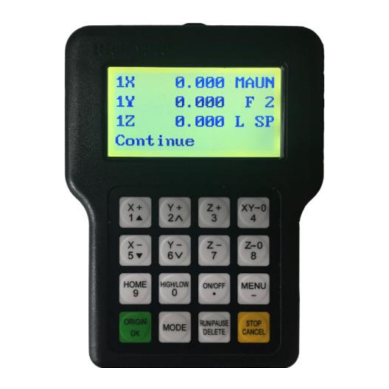
Beijing RichAuto S&T Co., Ltd. 1.2 Description of each component 1.2.1 Handle As shown below,including 6 parts: Handle Screen:128 * 64 resolution LCD to display the machine motion,system settings and other information. Button board:Contains 16 buttons to input system parameter information and operate the machine. -
Page 10: Interface Board
Beijing RichAuto S&T Co., Ltd. 1.2.2 Interface board As shown below,including 5 parts 50-pin data cable Interface J7:Output control terminal X-Axis Motor Y-Axis driver control J8:Input control terminal Z-Axis terminal C-Axis DC24V Input terminal 50-pin data cable port:connect handle with interface board. -
Page 11: Interface Board Shell Size
System”,“Format System”,and then restart the system. 2. Handle Buttons Introduction 2.1 Buttons introduction RichAuto motion control system defines 16 buttons according to functional requirements. Each button has one or more functions under different work status. Forging ahead and determined to win... -
Page 12: Usage Mode
Beijing RichAuto S&T Co., Ltd. Buttons picture 2.2 Usage mode RichAuto control system provide two modes of buttons’ operation,including one-touch button & Combination button. One-touch button:Press one button on handle. Combination button:Press two buttons at the same time to achieve the operation;the operation step: press one main function button and meanwhile press a second accessibility button, and then release the two buttons at the same time to realize the combination button operation. -
Page 13: Detail Information For Buttons Function
Beijing RichAuto S&T Co., Ltd. Set stop position ― ‖ +― ‖ System upgrade ― ‖+― ‖ Quit buttons check ― ‖+― ‖ 2.3 Detail information for buttons function Name Function Positive movement of X axis, menu upward , figure 1 inputting... -
Page 14: Wiring Instructions
Beijing RichAuto S&T Co., Ltd. Spindle start/stop, decimal point inputting Enter menu setting, negative sign inputting ,check information during processing Back to work origin,confirm motions /inputting/operating Manual mode, continue/step/distance to select Run or pause processing,delete inputting data, different property selecting in... -
Page 15: Interface Board I / O Description
Beijing RichAuto S&T Co., Ltd. 3.2 Interface board I / O description Pin functions Port Port Signal description Notes and parameters lable definition 24V+ +24V DC power input Supply DC24V 24V(≧3A) interface board 24V- Power GND Common anode Output 5V... - Page 16 Beijing RichAuto S&T Co., Ltd. Pin functions Port Port Signal description Notes and parameters lable definition Logic low FWD/REV Connect FWD&DCM,do Logic low not connect Y01 Multi-Speed 1 Logic low Multi-Speed 2 Logic low Multi-Speed 3 Logic low Alarm indicator...
-
Page 17: Hardware Wiring
RichAuto control system realizes its control through the connection between the interface board and CNC machine. Interface board terminal can be divided into input terminal and output terminal Input terminal:INPUT SIGNAL DC24V(Power Supply) - Page 18 Beijing RichAuto S&T Co., Ltd. 2. Tool-setting input 3. X5-X8 e.g.-Servo alarm Alarm signal normal open,wiring in series(modify the definition of X5 level. Alarm signal normal open, wiring in parallel Forging ahead and determined to win...
- Page 19 Beijing RichAuto S&T Co., Ltd. Output terminal X pulse signal wiring Y and Z are the same as X : Stepper driver :Σ-7 same as Σ-V Servo driver Σ- Σ-7 same as Σ-V : Motor Brake YASKAWA ),Set Pn50F=0300 :...
- Page 20 Beijing RichAuto S&T Co., Ltd. OUTPUT SIGNAL Y1-Y4 Count 3-1 Count 3-2 Count 1(ON/OFF) Spindle State CAUTION: FWD and DCM has Connected in Parallel in some inverters, plesae do not need to connect Y1 in such situations, you only need to connect DCM with GND of interface board, without having to reset the spindle gear.
-
Page 21: Commissioning Of The Machine And Control System
The machine is in good connection if all the above setting is ok. 4. Menu Description 4.1 Menu category According to menu function,RichAuto sytem menu divided into RichAuto A1X MACHINE SETUP AUTO PRO SETUP... - Page 22 ‖ to move cursor to where users want to modify.Press ― ‖,input the new number,and press ― ‖ to save. 2. Table Size RichAuto system make the table size as the soft limit values, in order to prevent machine Forging ahead and determined to win...
- Page 23 Beijing RichAuto S&T Co., Ltd. move over travel,machine size must be less than or equal to the value of the actual motion displacement machine. Setting: Enter ―Table Size‖, press ― ‖/― ‖ to move cursor to where users want to modify.Press ―...
- Page 24 Beijing RichAuto S&T Co., Ltd. and reduce the operating speed of the entire graph. System default:linear acceleration is 800 mm/s curve acceleration is 1000 mm/s , the proposed curve acceleration is 1-1.5 times the linear acceleration value. 6. Start Speed Unit:mm/minute The speed of axis started directly from standstill.
-
Page 25: Auto Pro Setup
Beijing RichAuto S&T Co., Ltd. too much;if smaller, Z axis can’t touch workpiece. This parameter can only take effect when user use auto toolsetting function. 9. Max Spd Limit(Max Speed Limit) Unit:mm/minute Set machine top speed, it only takes effect during processing, system default max speed X,Y is―60000000 mm/minute‖, ―Z+‖... - Page 26 Beijing RichAuto S&T Co., Ltd. 1. Work Speed Unit:mm/minute Including work speed and fast speed,system default is 3000 mm/minute 2. Safe Height Unit:mm The height of Z axis rise during processing. System default is 40.000 mm 3. Auto Scale Actual processing speed=work speed*auto scale, system default auto scale does not affect the fast speed 4.
- Page 27 Beijing RichAuto S&T Co., Ltd. ” move cursor to where users want to modify, press ― ‖ Press “ ” / “ to save 6. G Code Setup Set special G code attribute, according to the actual need to make changes.
-
Page 28: System Setup
Beijing RichAuto S&T Co., Ltd. 8. Work Array Set array parameter,including columncount,Rowcount,Columnspace,Rowspace,Interval(unit: ms) Columnspace:File spacing of X direction Rowspace:File spacing of Y direction Total Processing times= columncount* Rowcount Interval:System default 0,it means no wait. During processing,if users need to change processing materials after completion of each processing,you need set time interval a negative number.When the first time processing is... - Page 29 Beijing RichAuto S&T Co., Ltd. 1. Languages Change system display language,users can choose Chinese and English. 2. Data Initial After data initial system parameters will restore to factory setting. 3. Inner Format Wipe the internal files,it will not damage the system parameters.
- Page 30 Beijing RichAuto S&T Co., Ltd. 20-digit password,you need enter the new 20-digit password,and then all the passwords will be cracked. Setting:Press ― ‖to enter ―Probation Password‖,inpur the new password,and then press― ‖to save. 7. Backup Pas(Backup Password) Prevent users overwritten the original correct parameters in the parameter backup disorder or misuse case.
- Page 31 Beijing RichAuto S&T Co., Ltd. password work according to top-down order, if you do not set trial 1 password,only set trial 2-4,it will work according to 2-4 order. The operation of Data Initial,Inner Format,Wipe Cache should not crack the password.
-
Page 32: Operate File
Beijing RichAuto S&T Co., Ltd. ”to save. The screen will display: Enter the password,press“ time password updated successfully,please restart the control system. Restart the handle,and system will work normally. NOTE:If engraving machine manufacturers forgot all password, you can contact our company and tell us 20-digit original password under “SYSTEM SETUP-Probation pas”... -
Page 33: Version View
Beijing RichAuto S&T Co., Ltd. 2. Del File(Delete File) Delete files of inner. 3. View File View the files and G codes of U disk or inner. 4. Pro Info(Processing Information) System power on, it will statistical the times of successful processing by file name, if system power off,the data will disappear. -
Page 34: Machine Operation
5.2 Import processing files Before processing, generally we should import files. RichAuto system has 2 ways for processing: U disk file processing, inner file processing. Directly import the processing file into U disk, then run the handle. -
Page 35: Manual Speed Switching And Adjusting
Beijing RichAuto S&T Co., Ltd. 5.3.1 Manual speed switching and adjusting Speed mode switching There are two speed modes: high speed and low speed. We can change mode by press ― ‖. The speed mode you choose will decide the processing speed. -
Page 36: Manual Testing Input And Output
Beijing RichAuto S&T Co., Ltd. 、 、 、 、 、 direction button .Its motion speed is decided by current speed mode. NOTE:If uesers release the button immidiately after pressing the button(shorter than 0.5s), machine will automatically move to the nearest grid point. It always stop on grid point when the motion mode is over.Continous mode suitable for crude regulation of machine coordinate... - Page 37 Beijing RichAuto S&T Co., Ltd. switch signal. Manual trigger the corresponding signal switch,if the corresponding arrow flip so,the signal is normal.If not,please check corresponding switches or 50-pin cable and interface board. NOTE:Different from Voltage Setup. Bottom arrrows represent output signal: the former 4 number 0,1,2,3 corresponding to spindle on/off、spindle speed 1-3.4,5 corresponding to alarm indicator, running indicator.
-
Page 38: Manual Switching Coordinate System
Beijing RichAuto S&T Co., Ltd. coordinate system is a fixed point relative to the workpiece, but relative to the origin of machine coordinate system is floating. RichAuto-A1X provide a machine coordinate system and nine work coordinates system, press “ ” + “... -
Page 39: Choose Processing File
Beijing RichAuto S&T Co., Ltd. follow: Move X,Y and Z to the position which will start to process the file on workpiece. Afterwards, press zero clearing ― ‖ can set the origin of X,Y axis. Press zero clearing ― ‖ to set the origin of Z axis. -
Page 40: Operations During Processing
Beijing RichAuto S&T Co., Ltd. Press ― ‖ and ― ‖ to move cursor, press ― ‖ to set the value (next value setting is the same as this one), then pess ― ‖ to save, the system will check the processing code and start to process when checking finished. - Page 41 Beijing RichAuto S&T Co., Ltd. 5.5.2 Pause & adjust position Press ― ‖ pause processing. The right upwards of screen will change from―MAUN‖ to ―PAUZ‖and machine paused processing except the rotating of spindle. Shown below: 7.000 PAUS 8.000 -2.000 H SP User will start At this moment, the user is allowed to adjust the position of X, Y and Z axis.
- Page 42 Beijing RichAuto S&T Co., Ltd. If we want to save breakpoint, press ― ‖,the screen displays break list(totally 8), press ― ‖、― ‖to choose the save position and then press ― ‖ to save, system auto go to standard interface. If we want to continue processing from the breakpoint, we can choose the combination button ―...
-
Page 43: Advanced Processing
Beijing RichAuto S&T Co., Ltd. ‖to continue unfinished processing, it will display stop line No, and the line Press― number can be chosen. Press― ‖ cancel the power off protection. 5.6 Advanced Processing Advanced processing is designed for some special requests, it contains: Array work, Resume work, Tool changing, Part work, Calculate bound, Mill plane, step work file, Calculate work time, Find break NO. -
Page 44: Resume Work
Beijing RichAuto S&T Co., Ltd. pressing ― ‖. CAUTION:Set interval to a negative value if users want a manual control during array processing. 5 . 6 . 2 Resume work Steps as follows: Press ― ‖、― ‖ to move cursor to resume work, press ―... -
Page 45: Calculate Bound
Beijing RichAuto S&T Co., Ltd. After read the file, press ― ‖the screen display line 1 of the code, press ― ‖, prompted ―input start number: displays total lines‖, input number of start line and press ― ‖to confirm, if input wrong number, just press ―... -
Page 46: Calculate Work Time
Beijing RichAuto S&T Co., Ltd. Press ― ‖ or ― ‖to move cursr to choose the mill type. Press ― ‖ to enter the scan mill set, it includes: Scan type, Width, Height, Diameter, Depth, Z Step, T Ratio. Press ―... -
Page 47: Find Break No
Beijing RichAuto S&T Co., Ltd. processing file, the system will display total processing time. Different processing speed will correspond to different processing time. 5.6.8 Find break no If fail or forget to save the breakpoint,but not change work origin,after changing new tool,... - Page 48 Beijing RichAuto S&T Co., Ltd. Select Update File 选择 U 盘文件 UDisk File U 盘文件件 WENJIAN Internal File Recent File Choose Processing file,input correct parameters: Scale work param 选择 U 盘文件 scale 1.000 U 盘文件件 WENJIAN scale 1.000 scale 1.000 and then press “...
-
Page 49: A12 Plasma Cutting Motion Control System
Beijing RichAuto S&T Co., Ltd. 6. A12--Plasma Cutting Motion Control System 6.1 Handle and buttons introduction One-touch button and Combination button are same to A11,and the shell color of A12 is brown. Handle Buttons Function Arc On/Off, decimal point inputting The handle and interface board of A12 make special anti-interference,which make system work normally during strong interference. - Page 50 Beijing RichAuto S&T Co., Ltd. OUTPUT SIGNAL 2-axis with cylinder delay 1. 2-axis 2. 3-axis Forging ahead and determined to win...
-
Page 51: Parameters Description
Beijing RichAuto S&T Co., Ltd. 6.4 Parameters description 1. Axis Prohibited(MACHINE SETUP) If it is a two-axis plasma cutting machine, users can choose to set t Z-axis disable, and all relevant parameters about Z axis will no longer be meaningful. -
Page 52: A15--Multi-Spindle Motion Control System
Beijing RichAuto S&T Co., Ltd. 7. A15--Multi-spindle Motion Control System 7.1 Handle and buttons introduction The color of A15 handle is brown: Handle Buttons Special combination button Combination button Function Cylinder change over “ ”+ “ ” Calculate Z axis offset value of each “... -
Page 53: Spindle Wiring
Beijing RichAuto S&T Co., Ltd. 7.3 Spindle wiring 1. Count 1(Spindle On/Off): One spindle with one inverter, spindle 3,4 same as 1,2. 2. Count 3,multi-speed:One spindle with one inverter, spindle 3,4 same as 1,2. Forging ahead and determined to win... -
Page 54: Multi-Spindle Setup
Beijing RichAuto S&T Co., Ltd. 3. Two spindles with one inverter 7.4 Multi-spindle setup 1. Tool Setup: (MACHINE SETUP) Tool Count:Input spindle count,Max 4. Offset: Offsets of X,Y: Input by measuring. ”+ “ ”,switch to spindle 1 Chuck every spindle with sharp tool,press“... - Page 55 Beijing RichAuto S&T Co., Ltd. spindle 2(note that positive or negative). Same to spindle 3,4. Steps: Press “ ” to get in “Tool Setup” , Screen displays “Press OK key to set tool offset by manual mode,it’s very simple but not accurate,press cancel to set by mumber.”,and then ”,the screen shows:...
-
Page 56: G Code Example
Beijing RichAuto S&T Co., Ltd. The machine is equipped with C.A.D(Tool sensor) Firstly, get in ―SYSTEM SETUP-Function Confi-ToolSet‖,choose Atuo. Press “ ” + “ ” ,switch to spindle 1, and then press “ ” “ ” , system will automatically move Z axis to the surface of C.A.D(Tool sensor),after touching the surface,system will automatically switch to spindle 2,repeat the same operations to calculate all... -
Page 57: A18--Four-Axis Linkage Motion Control System
Beijing RichAuto S&T Co., Ltd. 8. A18--Four-axis Linkage Motion Control System 8.1 Handle buttons introduction Combination button Function Set X axis and Y axis work “ ”+ “ ” origin Set Z axis and A axis work “ ”+ “... -
Page 58: Parameters Description
Beijing RichAuto S&T Co., Ltd. 8.3 Parameters description Pulse equiv:Unit:ms(MACHINE SETUP) Rotation axis stepper driver: Formula = pulses per revolution / angles per revolution ( 360° ) 360 ° ∗driver subdivision stepper angle pulse = 360° ∗transmission ratio Rotation axis servo driver:Handle pulse equivalent(400)*360* mechanical transmission ratio Work Orig Offset:... -
Page 59: Appendix
Beijing RichAuto S&T Co., Ltd. 9. Appendix 9.1 System upgrade Copy upgrade file to U disk,and insert U disk into handle,file format:extension ******. & shown as rz-xxxx. U Disk Upgrade Method 1 1. Press “ ” , and then select “System Setup” , press “... -
Page 60: U-Disk Function
Beijing RichAuto S&T Co., Ltd. 9.2 U-disk Function “Product ID:A010XXXX & Update Users can copy file from computer to handle after ” version. Connect handle and computer by USB cable, users can find Version rz-1967 portable storage device on the computer , and then copy processing files from computer to handle inner. -
Page 61: Servo Driver Parameters
Beijing RichAuto S&T Co., Ltd. 9.3 Servo driver parameters YASKAWA Σ-7、Σ-Ⅴ 9.3.1 1. Wiring diagram(Y、Z same as X)Set PnA=8170,do not connect pin-40 Motor brake: Σ-7 same as Σ-Ⅴ Forging ahead and determined to win... - Page 62 Beijing RichAuto S&T Co., Ltd. 2. Parameter setting Para. Function Value Description *Pn000 Function 0010 Bit 0:Set 0,positive rotation at positive rotation selection basic command switch 0 Bit 1:Set 1,position control mode(pulse sequence command) Bit 0 : Set 5,select the instruction mode as...
-
Page 63: Panasonic Minas A5
Beijing RichAuto S&T Co., Ltd. chang he direction of the arrow facing up) The same below. ↓:normally open,↑:normally colsed 9.3.2 PANASONIC MINAS A5 1. Wiring diagram(Y、Z same as X)Set Pr4.05=8618883,do not connect pin-29 Motor brake: Forging ahead and determined to win... - Page 64 Beijing RichAuto S&T Co., Ltd. 2. Parameter setting Para. Function Value Description *Pr0.00 Setting the direction If the motor rotation direction opposite to the of rotation actual needs, set 1. *Pr0.01 Select control mode 0:Position mode,1: velocity mode,2: torque mode 0:Photo-coupler input (PULS1,PULS2,SIGN1,SIGN2)...
-
Page 65: Delta Asda-A2&B2
Beijing RichAuto S&T Co., Ltd. 9.3.3 DELTA ASDA-A2&B2 Wiring diagram(Y、Z same as X)Set P2-10=1,do not connect pin-9 A2 Series PULSE,/PULSE,SIGN,/SIGN correspond pin-43,41,36,37, COM- corresponds pin-45/47/49 Motor brake: A2 series BK-,BK+ correspond CN1-1,26 Forging ahead and determined to win... - Page 66 Beijing RichAuto S&T Co., Ltd. Parameter setting DELTA Function Value Description ASDA-B2 P1-00 External pulse train Bit 0:2--pulse+direction input type Bit 2:1--negative logic Bit 3:Maintaining the set value.Since switching control mode is not used,bit 3--0. *P1-01 Set control mode 0000 Bit 2:0--forward rotation(CCW)(from the view of...
- Page 67 Beijing RichAuto S&T Co., Ltd. DELTA Function Value Description ASDA-A2 P1-00 External pulse Bit 0:2--pulse+direction train input type Bit 2:1--negative logic Bit 3:Maintaining the set value.Since switching control mode is not used,bit 3--0. *P1-01 control 0000 mode Bit 2:0--forward rotation(CCW)(from the view of load) Bit 1,0:00--position control mode...
-
Page 68: G Code List
Beijing RichAuto S&T Co., Ltd. 9.4 G code list G code list of A1X &A5X Rapid positioning Linear interpolation Circular interpolation CW Circular interpolation CCW Dwell (Unit: millisecond) Selection of XY coordinate plane Selection of ZX coordinate plane Selection of YZ coordinate plane... - Page 69 Beijing RichAuto S&T Co., Ltd. pinpoint signal edge (similar to backing home) G103 Move with processing speed until the signal is triggered. G104 Move with fast speed until the signal is triggered. Spindle on(CW rotation) Spindle on(CCW rotation) Spindle stop...
-
Page 70: Tool Setting(Tool Measurement)
Beijing RichAuto S&T Co., Ltd. 9.5 Tool setting(Tool measurement) Tool setting is a process to set up a workpiece coordinate system in machine coordinate system.To put it in other words,tool setting aims to set the workpiece origin. Including:fixed calibration,mobile calibration. - Page 71 Beijing RichAuto S&T Co., Ltd. Fixed calibration process: 1.Automatically locate to the Specified position rapidly Fix this position Position before according to the position tool setting of tool sensor 2.Up after tool setting Tool sensor Machine Table Fixed calibration refers to measurement operation at a certain fixed position on the machine.
-
Page 72: Mobile Calibration
Beijing RichAuto S&T Co., Ltd. origin of X,Y,Z axis. 2. Press ― ‖+― ‖to start first time tool setting.The system will record value of offset automatically. 3. Start to processing after first time tool setting. 4. If change another tool or the tool nose has a certain degree of wear and tear,press ―... - Page 73 Beijing RichAuto S&T Co., Ltd. Mobile calibration process: 1.Manually move to the upper side of tool senro(C.A.D.) Manually move the Position before machine to this positon tool setting 2.Up after tool setting Tool sensor Workpiece Machine Table Wiring: 1. The white cable connects to X4(TS,interface board)...
- Page 74 Beijing RichAuto S&T Co., Ltd. Instructions: The signal cable of tool sensor connects to X4(X5-A18), alligator clip connects to GND-INPUT SIGNAL.(alligator clip also can be cliped on the spindle if the spindle connected to GND) Place tool sensor onto workpiece,move Z axis to the upper side of the tool sensor in manual mode,and press ―...
-
Page 75: Calculate Pulse Equivalent
Beijing RichAuto S&T Co., Ltd. 9.6 Calculate pulse equivalent 9.6.1 Stepper driver 1. linear axis Unit: pul/mm Formula = pulses per revolution / distance per revolution Pulses per revolution formula: (360 ° /stepper angle)* Driver subdivision Some stepper drivers mark pulse number directly. - Page 76 Beijing RichAuto S&T Co., Ltd. Rack drive: ► Straight rack: 360 ° ×Driver subdivision Stepper angle pulse = rack module ×gear teeth number ×π×transmission ratio ► Helical rack: 360 ° ×Driver subdivision ×cos (helical angle ) Stepper angle pulse = rack module ×gear teeth number ×π×transmission ratio...
-
Page 77: Servo Driver
Beijing RichAuto S&T Co., Ltd. ► Helical rack 1600 pulse equivalent = ′ ″ 1.25×23×3.141592654 ×0.2÷cos (19° 31 ) 1600×cos (19.52833333 ) = 83.478 1.25×23×3.141592654 ×0.2 NOTES:1.25× 23× 3.141592654× 0.2= 18.0641577605 cos(19.52833333)= 0.94247630504668681677372940102406 1.25× 23× 3.141592654× 0.2÷ cos(19.52833333)=19.1666969915≈19.1667 3. Rotation axis Unit: (pul/° )... - Page 78 Beijing RichAuto S&T Co., Ltd. YASKAWA- Denominator Pn210 Screw drive screw pitch=5mm,Pn210= 1000× 5=5000 Rack drive rack module:1.25,gear teeth number:23,π:3.141592654,transmission ratio:1/5(0.2) helical angle:19° 31′42″(≈19.52833333° ) Straight rack Pn210 = 1000× 1.25× 23× 3.141592654× 0.2=18064 Helical rack Pn210 = 1000×...
- Page 79 Beijing RichAuto S&T Co., Ltd. 3. Calculate pulse equivalent according to fixed electronic gear ratio B2: Electronic gear ratio default--16/10,A2: Electronic gear ratio default--N=128/10 e.g. B2:Set P1-44=1,P1-45=1,Encoder pulses 2500× 4=10000 Screw drive 10000 screw pitch=5mm,pulse equivalent = = 2000 ...
-
Page 80: Proportion Calculation Method
Beijing RichAuto S&T Co., Ltd. 9.6.3 Proportion calculation method If there is an error according to the formula or no relevant data to calculate, it can be calculated according to the proportion method. Suppose handle pulse equivalent A, press "... -
Page 81: Common Problems And Troubleshooting
Beijing RichAuto S&T Co., Ltd. 9.7 Common problems and troubleshooting 9.7.1 Solutions of the faults display on the screen 1. Screen flicker or automatically restart Power supply is insufficient. Check power supply if there are problems, and change high-quality power supply to solve the problems. -
Page 82: Faults In Practical Operation
Beijing RichAuto S&T Co., Ltd. does not recognize, interrupt handling. Recommend using professional simulation software to view the program whether there is an illegal character. Delete all illegal characters. 9.7.2 Faults in practical operation 1. The file size does not match the size of the actual set Pulse equivalent is wrong. - Page 83 Beijing RichAuto S&T Co., Ltd. 5. Repeating the same processing file after backing to the machine origin,Z axis depth is not the same Machining countertop is uneven or processing object not firmly fixed, re-milling countertop adjust the flatness. Z-axis origin detection switch repeat positioning accuracy error, causing each Z axis homing error.
- Page 84 Beijing RichAuto S&T Co., Ltd. 8. Abnormally working when processing or the actual file is different from theoretical file 。 The system disorder. Too much external interference.Refresh connection. (Separate low voltage from high voltage, "GND" of inverter separated from the other components ).
-
Page 85: Electrical Components And Wiring Problem
Beijing RichAuto S&T Co., Ltd. 9.7.3 Electrical components and wiring problem 1. One axis or multi-axis only one-way movement after handle power up There is something wrong with the cable connect the interface board with the motor driver, check the connection. - Page 86 Beijing RichAuto S&T Co., Ltd. wiring in series) 7. Press spindle on,but spindle does not start Check wiring,if normal,check interver and spindle motor. Check 50-pin cable. Check interface board.Press ― ‖ to start spindle,use multimeter to measure Y1 and GND whether conducting,if not,maybe interface or 50-pin cable is broken.
Need help?
Do you have a question about the A1X and is the answer not in the manual?
Questions and answers