GW Instek AFG-3021 User Manual
Arbitrary function generator
Hide thumbs
Also See for AFG-3021:
- Quick start manual (40 pages) ,
- User manual (422 pages) ,
- Manual (8 pages)

Related Manuals for GW Instek AFG-3021


Summary of Contents for GW Instek AFG-3021
- Page 1 Arbitrary Function Generator AFG-3021, 3022, 3031 & AFG-3032 USER MANUAL GW INSTEK PART NO. 82FG-30320EC1 ISO-9001 CERTIFIED MANUFACTURER 北京海洋兴业科技股份有限公司 电话:010-62176775 网址:www.hyxyyq.com...
- Page 2 August 2016 edition This manual contains proprietary information, which is protected by copyright. All rights are reserved. No part of this manual may be photocopied, reproduced or translated to another language without prior written consent of Good Will Corporation. The information in this manual was correct at the time of printing. However, Good Will continues to improve its products and therefore reserves the right to change the specifications, equipment, and maintenance procedures at any time without notice.
-
Page 3: Table Of Contents
TABLE OF CONTENTS Table of Contents SAFETY INSTRUCTIONS ........6 GETTING STARTED ........12 Main Features ..............12 Panel Overview ..............15 Setting up the Function Generator ........24 QUICK REFERENCE ........26 How to use the Digital Inputs ........... 28 How to use the Help Menu .......... - Page 4 AFG-3021/3022/3031/3032 User Manual Burst Mode ..............147 SECONDARY SYSTEM FUNCTION SETTINGS ..............159 Save, Recall or Delete ............160 Selecting the Remote Interface ........164 System and Settings ............169 DUAL CHANNEL & MULTI-UNIT OPERATION ..............178 Dual Channel Settings ............. 179 Multi-Unit Syncing ............
- Page 5 Save and Recall Commands ..........385 Error Messages ............... 387 SCPI Status Registers ............400 APPENDIX ........... 406 Fuse Replacement ............406 AFG-3021, AFG-3022, AFG-3031 & AFG-3032 Specifications ..................407 Declaration of Conformity ..........414 ARB Built-In Waveforms ..........415 INDEX ............423 北京海洋兴业科技股份有限公司...
-
Page 6: Safety Instructions
AFG-3021/3022/3031/3032 User Manual AFETY INSTRUCTIONS This chapter contains important safety instructions that should be followed when operating and storing the function generator. Read the following before any operation to ensure your safety and to keep the function generator in the best condition. - Page 7 SAFETY INSTRUCTIONS Do not dispose electronic equipment as unsorted municipal waste. Please use a separate collection facility or contact the supplier from which this instrument was purchased. Safety Guidelines Do not place heavy objects on the instrument. General Guideline Do not place flammable objects on the ...
- Page 8 AFG-3021/3022/3031/3032 User Manual AC Input voltage: 100 - 240V AC, 50 - 60Hz. Power Supply Connect the protective grounding conductor of WARNING the AC power cord to an earth ground to prevent electric shock. Fuse type: Fuse ...
- Page 9 SAFETY INSTRUCTIONS Disconnect the power cord before cleaning the Cleaning the function generator. function generator Use a soft cloth dampened in a solution of mild detergent and water. Do not spray any liquid into the function generator. Do not use chemicals containing harsh products ...
- Page 10 AFG-3021/3022/3031/3032 User Manual Do not dispose this instrument as unsorted Disposal municipal waste. Please use a separate collection facility or contact the supplier from which this instrument was purchased. Please make sure discarded electrical waste is properly recycled to reduce environmental impact.
- Page 11 SAFETY INSTRUCTIONS Power cord for the United Kingdom When using the function generator in the United Kingdom, make sure the power cord meets the following safety instructions. NOTE: This lead/appliance must only be wired by competent persons WARNING: THIS APPLIANCE MUST BE EARTHED IMPORTANT: The wires in this lead are coloured in accordance with the following code: Green/ Yellow:...
-
Page 12: Getting Started
ETTING STARTED The Getting started chapter introduces the function generator’s main features, appearance, set up procedure and power-up. Note: Throughout this manual, “AFG-30XX” refers to the AFG-3021, AFG-3022, AFG-3031 & AFG-3032, unless stated otherwise. Main Features Model name Frequency Channels... - Page 13 GETTING STARTED -Ten 8 M waveform memories -True waveform output to display -User define output section -D W R (Direct Waveform Reconstruction) capability -Waveform editing capability sans PC -N Cycle and Infinite output mode selectable -60dBc low distortion sine wave ...
- Page 14 AFG-3021/3022/3031/3032 User Manual Interface: Standard: LAN, USB Optional: GPIB Interface 4.3 inch color TFT LCD (480 × 272) Graphical User Interface AWES (Arbitrary Waveform Editing Software) PC software 北京海洋兴业科技股份有限公司 电话:010-62176775 网址:www.hyxyyq.com...
-
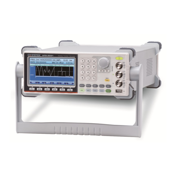
Page 15: Panel Overview
GETTING STARTED Panel Overview Front Panel AFG-3021/3031 LCD Display Number Scroll Wheel Selection Power Switch keys A F G -3 0 3 1 Arbitrary Function Generator Output SYNC Terminals MAIN MAIN Output Output key Waveform FREQ/Rate AMPL DC Offset UTIL... - Page 16 AFG-3021/3022/3031/3032 User Manual TFT color LCD display, 480 x 272 resolution. LCD display Activates the functions which Function keys: appear in the bottom of the LCD F1~F6 display. Waveform is used to select a Operation keys Waveform waveform type. The FREQ/Rate key is used to set FREQ/Rate the frequency or sample rate.
- Page 17 GETTING STARTED The Output key is used to turn on Main Output MAIN or off the waveform output. (AFG-3021/3031) Output CH1/CH2 Output key. These CH1/CH2 keys are used to turn the output Output Output on or off for each individual (AFG-3022/3032) channel.
- Page 18 AFG-3021/3022/3031/3032 User Manual Modulation output terminal for Output terminals the AM, FM, PWM, PM, SUM or (AFG-3021/3031) sweep function. The SYNC output terminal SYNC outputs a TTL logic level signal in phase with the zero phase position of the main output. 50Ω...
- Page 19 GETTING STARTED The standby key is used to turn Standby key the function generator on (green) or to put the function generator into standby mode (red). Used to select digits when editing Selection keys parameters. The scroll wheel is used to edit Scroll Wheel values and parameters.
- Page 20 AFG-3021/3022/3031/3032 User Manual Rear Panel AFG-3021/3031 GPIB Power Switch Power Disconnect power cord and test GPIB leads before replacing fuse WARNING socket and FUSE RATING To avoid electric shock the power cord protective grounding conductor AC 250V must be connected to ground.
- Page 21 Power input: 100-240V AC Power Socket Input and fuse 50-60Hz. Fuse: AFG-3022/3032: T1A/250V AFG-3021/AFG-3031: T0.63A/250V For the fuse replacement procedure, see page 406. Main power switch. Power Switch The USB B connector is used to USB B port connect the function generator to a PC for remote control.
- Page 22 AFG-3021/3022/3031/3032 User Manual 24 pin female GPIB GPIB GPIB connector for PC remote control. 北京海洋兴业科技股份有限公司 电话:010-62176775 网址:www.hyxyyq.com...
- Page 23 GETTING STARTED Display Parameter Waveform Window Display Parameter Waveform Window Display Soft Menu Keys These windows are used to edit the parameter Parameter values for CH1 and CH2. Windows Waveform Display The Waveform Display is used give an indication of the expected waveform output for each channel. The function keys (F1~F6) below the Soft Menu Soft Menu Keys keys correspond to the soft keys.
-
Page 24: Setting Up The Function Generator
AFG-3021/3022/3031/3032 User Manual Setting up the Function Generator This section describes how to adjust the handle Background and power up the function generator. Pull out the handle Adjusting the sideways and rotate stand Place the unit horizontally, or tilt the stand. - Page 25 GETTING STARTED 1. Connect the power cord to Power Up the socket on the rear panel. 2. Turn on the power switch on the rear panel. 3. Press and hold the Standby key on the front panel to turn the machine on. The Standby On standby key will change from red (standby) to green...
-
Page 26: Quick Reference
AFG-3021/3022/3031/3032 User Manual UICK REFERENCE This chapter lists operation shortcuts, built-in help coverage, and default factory settings. Use this chapter as a quick reference for instrument functions. For detailed explanations on parameters, settings and limitations, please see the Operation chapter(page 70), Modulation chapter(page 90), Secondary System Function Settings chapter (page 159), Dual Channel &... - Page 27 Sweep - Type/MOD = Amplitude......... 61 Burst – N Cycle ..............62 Burst - Gate ................62 CH1 / CH2 (AFG-3022/AFG-3032 Only) ......63 UTIL (AFG-3021/3031) ............63 UTIL (AFG-3022/AFG-3032) ..........64 UTIL - Interface ..............64 UTIL - Interface - LAN ............65 UTIL - Interface - LAN - Config - Manual ......
-
Page 28: How To Use The Digital Inputs
QUICK REFERENCE How to use the Digital Inputs The AFG-30XX has three main types of digital Background inputs: the number pad, selection keys and scroll wheel. The following instructions will show you how to use the digital inputs to edit parameters. 1. -
Page 29: How To Use The Help Menu
Every key and function has a detailed description Background in the help menu. 1. Press UTIL. UTIL 2. Press System (F4)[F5 for the System AFG-3021/3031]. 3. Press More (F5). More 4. Press Help (F2). Help 5. Use the scroll wheel to navigate to a help item. Press Select to choose the item. - Page 30 AFG-3021/3022/3031/3032 User Manual Modulation Explains how to create Function Modulated waveforms. Sweep Function Provides help on the Sweep function. Burst Function Provides help on the Burst function. DSO Link Provides help on DSO link. Hardcopy Explains how to use the Hardcopy function.
- Page 31 QUICK REFERENCE 7. Use the scroll wheel to navigate to each help page. 8. Press F6 to return to the Return previous menus. 北京海洋兴业科技股份有限公司 电话:010-62176775 网址:www.hyxyyq.com...
-
Page 32: Selecting A Waveform
AFG-3021/3022/3031/3032 User Manual Selecting a Waveform Square Wave Example: Square wave, 3Vpp, 75%duty, 1 kHz 1. Press the Waveform Output Waveform Square key and select Square (F2). 2. Press Duty(F1), Duty followed by 7 + 5 + %(F5) 3. Press the FREQ/Rate... -
Page 33: Sine Wave
QUICK REFERENCE 3. Press the AMPL key, AMPL followed by 5 +VPP (F6). 4. Press the output key. Output Sine Wave Example: Sine wave, 10Vpp, 100kHz 1. Press the Waveform Output Waveform Sine key and select Sine (F1). 2. Press the FREQ/Rate FREQ/Rate key, followed by 1 + 0 Input: N/A... -
Page 34: Noise Wave
AFG-3021/3022/3031/3032 User Manual 3. Press Width (F1), Width uSEC followed by 5 + uSEC (F3). 4. Press the AMPL key, AMPL followed by 1 + 0 +VPP (F6). 5. Press the output key. Output Noise Wave Example: White noise output 1. - Page 35 QUICK REFERENCE 4. Press Order (F3). Order 5. Press Order (F1), Order Enter followed by 2 + Enter (F1). Press Amp(F2), Ampl followed by 5 + VPP (F2). Phase Degree Press Phase(F3), followed by 0 + Degree (F1). 6. Press the Order (F1), Order Enter followed by 3 + Enter...
-
Page 36: Modulation
AFG-3021/3022/3031/3032 User Manual Modulation Example: AM modulation. 100Hz modulating square wave. 1kHz Sine wave carrier. 80% modulation depth. 1. Press the MOD key Output and select AM (F1). 2. Press Waveform and Sine Waveform select Sine (F1). 3. Press the Freq/Rate... - Page 37 QUICK REFERENCE 9. Press MOD, AM (F1), Source Source (F1), INT (F1). 10. Press the output key. Output Example: FM modulation. 100Hz modulating square wave. 1kHz sine wave carrier. 100 Hz frequency deviation. Internal source. 1. Press the MOD key Output and select FM (F2).
-
Page 38: Fsk Modulation
AFG-3021/3022/3031/3032 User Manual 8. Press 1 + 0 + 0 + Hz (F3). 9. Press MOD, FM (F2), Source Source (F1), INT (F1). 10. Press the output key. Output FSK Modulation Example: FSK modulation. 100Hz hop frequency. 1kHz carrier wave. Triangle wave. 10 Hz rate. Internal source. - Page 39 QUICK REFERENCE 8. Press MOD, FSK (F3), Source Source (F1), INT (F1). 9. Press the output key. Output Example: PM modulation. 100Hz phase frequency. Sine wave shape. 180° phase deviation. 1kHz sine wave carrier. 1. Press the MOD key Output and select PM (F4).
-
Page 40: Sum Modulation
AFG-3021/3022/3031/3032 User Manual 8. Press 1 + 8 + 0 + Degree Degree (F1). SUM Modulation Example: SUM modulation. 100Hz SUM frequency. 50% SUM amplitude. 1kHz carrier sine wave. Triangle wave shape. Internal source. 1. Press the MOD key Output and select SUM (F5). -
Page 41: Pwm Modulation
QUICK REFERENCE 9. Press MOD, SUM Source (F5), Source (F1), INT (F1). 10. Press the output key. Output PWM Modulation Example: PWM modulation. 800Hz carrier wave. 15 kHz modulating sine wave. 50% duty cycle. Internal source. 1. Press Waveform and Output Square Waveform... -
Page 42: Sweep
AFG-3021/3022/3031/3032 User Manual 9. Press MOD, PWM Source (F6), Source (F1), INT (F1). 10. Press the output key. Output Sweep Example: Frequency sweep. Start frequency 10mHz, stop frequency 1MHz. Log sweep, 1 second sweep, manual trigger. 1. Press Sweep, Start... -
Page 43: Burst
QUICK REFERENCE 9. Press the output key. Output 10. Press Trigger (F1). Trigger Burst Example: Burst mode, N-Cycle (Internally triggered), 1kHz burst frequency, burst count = 5, 10 ms burst period, 0˚ burst phase, internal trigger, 10 us delay. 1. Press FREQ/Rate 1 Output FREQ/Rate kHz (F5). -
Page 44: Arb
AFG-3021/3022/3031/3032 User Manual 9. Press Burst, N Cycle N Cycle Trig Setup Burst (F1), TRIG Setup (F5), Delay Delay (F4). 10. Press 1 + 0 + uSEC uSEC (F2). 11. Press the output key. Output ARB – Add Built-In Waveform Example: ARB Mode, exponential rise. -
Page 45: Arb - Add Point
QUICK REFERENCE 1. Press ARB, Built in Output Built in Basic (F3), Basic (F1), More More Pulse (F5), Pulse (F4). 2. Press Frequency (F1), Frequency 1, kHz (F5). 3. Press Duty (F2), 25, Duty %(F5). Return ARB - Add Point Example: ARB Mode, Add point, Address 40, data 30,000. -
Page 46: Arb - Output Section
AFG-3021/3022/3031/3032 User Manual 3. Press Start Data (F2), Start Data 3 + 0, Enter (F5). Enter Return 4. Press Stop ADD (F3), Stop ADD 5 + 0, Enter (F5). Enter Return 5. Press Stop Data (F4), Stop Data 1 + 0 + 0, Enter (F5), Done (F5). -
Page 47: Arb - Output Infinite Cycles
QUICK REFERENCE 3. Press Length (F2), 1 + Length 0 + 0, Enter (F5). Enter Return 4. Press N Cycle (F4). N Cycle 5. Press Cycles (F1), 1 + Cycles Enter Return 0, Enter (F5). 6. To trigger the output Trigger once, press Trigger (F5). -
Page 48: Utility Menu
AFG-3021/3022/3031/3032 User Manual Utility Menu Save Example: Save to memory file #5. 1. Press UTIL, Memory Memory UTIL (F1). 2. Choose a file using the scroll wheel and Store Done press Store (F1), press Done (F5). Recall Example: Recall memory file #5. -
Page 49: Interface Lan
QUICK REFERENCE Interface LAN Example: LAN interface, DHCP IP configuration. 1. Press UTIL, Interface Interface UTIL (F2), LAN (F3). 2. Press Config (F2), Config DHCP DHCP (F1). 3. Press Done (F3). Done Interface USB Example: USB interface. 1. Press UTIL, Interface Interface UTIL (F2), USB (F2). -
Page 50: Dual Channel - Tracking
AFG-3021/3022/3031/3032 User Manual 2. Press ON (F1). Dual Channel – Tracking Example: Inverted tracking. AFG-3022, 3032 only. 1. Press UTIL, Dual Ch Output Dual Ch Tracking UTIL (F5), Tracking (F3). 2. Press Inverted (F3). Inverted 北京海洋兴业科技股份有限公司 电话:010-62176775 网址:www.hyxyyq.com... -
Page 51: Menu Tree
QUICK REFERENCE Menu Tree Convention Use the menu trees as a handy reference for the function generator functions and properties. The AFG- 3021/3022/3031/3032 menu system is arranged in a hierarchical tree. Each hierarchical level can be navigated with the operation or soft menu keys. Pressing the Return soft key will return you to the previous menu level. -
Page 52: Waveform - Pulse
AFG-3021/3022/3031/3032 User Manual Waveform - Pulse Waveform Pulse Width DUTY Rise Fall Edge Time Extended nSEC nSEC nSEC nSEC uSEC Return uSEC uSEC uSEC Return mSEC mSEC mSEC mSEC Return Return Return Return Waveform - More Waveform More Noise Harmonic... -
Page 53: Arb-Display
QUICK REFERENCE ARB-Display Display Horizon Vertical Next Page Back Page Overview Return Start Clear Clear Enter Enter Return Return Length High Clear Clear Enter Enter Return Return Center Center Clear Clear Enter Enter Return Return Zoom in Zoom in Zoom out Zoom out Return Return... -
Page 54: Arb-Edit
AFG-3021/3022/3031/3032 User Manual ARB-Edit Edit Point Line Copy Clear Protect Return Address Start ADD Start Start Done Clear Clear Clear Clear Enter Enter Enter Enter Start Return Return Return Return Clear Data Start Data Length Length Enter Return Clear Clear... -
Page 55: Arb-Built-In
QUICK REFERENCE ARB-Built-in Note: The following menu tree only lists where each built-in ARB waveform is located. Built in Basic Common 1 Common 2 Math More Return Sine abstan dlorentz attalt Trig Square havercosine rectpuls arccos arctan sinever Ramp sqrt stepresp sech abssin... -
Page 56: Arb-Built In-Basic
AFG-3021/3022/3031/3032 User Manual ARB-Built in-Basic Note: For brevity, only the “Basic” menu tree is listed for the ARB > Built-in menu tree system. The operation menu keys for all the other built-in ARB waveforms are mostly identical to the ones listed below. -
Page 57: Arb-Save
QUICK REFERENCE ARB-Save Save Start Length Memory Return Clear Clear Select Select Enter Enter Return New Folder Return Return Enter Char Back Space Save Return New File Enter Char Back Space Save Return Return ARB-Load Load Memory Return Clear Select Select Enter Return... -
Page 58: Arb-Output
AFG-3021/3022/3031/3032 User Manual ARB-Output Output Start Length Gate N Cycle Infinite Return Clear Clear Cycles Enter Enter Clear Return Return Return Enter Return Manual Trigger Return 北京海洋兴业科技股份有限公司 电话:010-62176775 网址:www.hyxyyq.com... -
Page 59: Mod
QUICK REFERENCE Source Source Source Phase Dev Source Source Degree Return Return Return Return Return Return PM Freq Depth Freq Dev Hop Freq SUM Ampl Duty Return Return Return Return AM Freq SUM Freq PWM Freq Shape Sine Return Return Square FM Freq FSK Rate... -
Page 60: Sweep - Type/Mod = Frequency
AFG-3021/3022/3031/3032 User Manual Sweep - Type/MOD = Frequency SWEEP TRIG Type Type/MOD Start Stop SWP Time More mSEC Go to the Type Sweep - Freq Return Frequency - Ampl Manual Return More menu Trigger Mode Return Return Return Cont Gate... -
Page 61: Sweep - Type/Mod = Amplitude
QUICK REFERENCE Sweep - Type/MOD = Amplitude SWEEP TRIG Type Type/MOD Start Stop SWP Time Return mSEC Type mVRMS mVRMS Freq VRMS VRMS Return Ampl Manual Return mVPP mVPP Trigger Mode Return Return Return Cont Gate TRIG Time Return Functions mSEC Linear Return... -
Page 62: Burst - N Cycle
AFG-3021/3022/3031/3032 User Manual Burst – N Cycle Burst N Cycle Cycles Infinite Phase Period TRIG Setup Return Clear Clear uSEC Degree mSEC Return Return Rise Return Fall Return Manual Trigger Return Delay nSEC uSEC mSEC Return Return Burst - Gate... -
Page 63: Ch1 / Ch2 (Afg-3022/Afg-3032 Only)
CH1 / CH2 (AFG-3022/AFG-3032 Only) Load Phase DSO-Link 50 OHM 0 Phase Search High Z Sync Int Return Degree Align Phase Return Return UTIL (AFG-3021/3031) UTIL Memory Interface Cal. Load System DSO-Link Go to the Go to the Search Store Self Test 50 OHM UTIL –... -
Page 64: Util (Afg-3022/Afg-3032)
AFG-3021/3022/3031/3032 User Manual UTIL (AFG-3022/AFG-3032) UTIL Memory Interface Cal. System Dual Ch Go to the Go to the Store Self Test Go to the UTIL – UTIL – Software Done UTIL – Dual Return Interface System Version Ch menu Recall... -
Page 65: Util - Interface - Lan
QUICK REFERENCE UTIL - Interface - LAN UTIL Interface Remote Config Done Return DHCP Auto IP Manual Go To UTIL – Interface – LAN Config – Manual menu Host Name Enter Char Done Return Done Return 北京海洋兴业科技股份有限公司 电话:010-62176775 网址:www.hyxyyq.com... -
Page 66: Util - Interface - Lan - Config - Manual
AFG-3021/3022/3031/3032 User Manual UTIL - Interface - LAN - Config - Manual UTIL Interface Config Manual IP Addr NetMask Gateway Done Return Done Done Done Clear Clear Clear Return Return Return UTIL - System UTIL System Language Display Opt. Clk Source... -
Page 67: Util - Dual Channel
QUICK REFERENCE UTIL - Dual Channel UTIL Dual Ch Freq Cpl Ampl Cpl Tracking Return Offset Inverted Return Return Return Ratio Enter Return Return 北京海洋兴业科技股份有限公司 电话:010-62176775 网址:www.hyxyyq.com... -
Page 68: Default Settings
AFG-3021/3022/3031/3032 User Manual Default Settings Here are the default panel settings which appear Preset when pressing the Preset key. Function Sine wave Output Config. Frequency 1kHz Amplitude 3.000 Vpp Offset 0.00V dc Output units Output terminal 50Ω Modulation Carrier Wave... - Page 69 QUICK REFERENCE Burst Frequency 1kHz Burst Ncycle Burst period 10ms Burst starting phase 0˚ Burst status Trigger source Internal (immediate) Trigger GPIB Address Interface config. Interface DHCP Calibration Menu Restricted Calibration 北京海洋兴业科技股份有限公司 电话:010-62176775 网址:www.hyxyyq.com...
-
Page 70: Operation
AFG-3021/3022/3031/3032 User Manual PERATION The Operation chapter shows how to output basic waveform functions. For details on modulation, sweep, burst and arbitrary waveforms, please see the Modulation and Arbitrary waveform chapters on pages 90 and 175. For information on the dual channel and multi-unit operation, please see page 179 &... -
Page 71: Select A Channel
OPERATION Select a Channel As the AFG-3022 or AFG-3032 are dual channel models, the desired output channel must first be selected before assigning the operation for that channel. CH1/CH2 Panel Operation 1. Press the CH1 or CH2 key. 2. The selected channel will be visible while the deselected channel will be dimmed. -
Page 72: Select A Waveform
AFG-3021/3022/3031/3032 User Manual Select a Waveform The AFG-30XX can output 8 standard waveforms: sine, square, triangle, pulse, ramp, noise, harmonic and DC waveforms. Sine Wave Panel Operation 1. Press the Waveform key. Waveform 2. Press F1 (Sine). Sine 北京海洋兴业科技股份有限公司 电话:010-62176775... -
Page 73: Setting A Square Wave
4. Use the selector keys and scroll wheel or number pad to enter the Duty range. 5. Press F5 (%) to choose % units. Range Frequency Duty Range ≤25MHz 20%~80% (20MHz AFG-3021/3022) 25MHz~≤30MHz 40%~60% 北京海洋兴业科技股份有限公司 电话:010-62176775 网址:www.hyxyyq.com... -
Page 74: Triangle Wave
AFG-3021/3022/3031/3032 User Manual Triangle Wave Panel Operation 1. Press the Waveform key. Waveform 2. Press F3 (Triangle). Triangle 北京海洋兴业科技股份有限公司 电话:010-62176775 网址:www.hyxyyq.com... -
Page 75: Setting The Pulse Width
OPERATION Setting the Pulse Width The pulse width settings depend on the rise & fall time settings or the edge time setting and the period settings, as defined below: Pulse Width - 0.625 * [(Rise Time - 0.6nS) + (Fall Time - 0.6nS)] ≧ 0 Period ≧... -
Page 76: Setting The Pulse Rise & Fall Time
AFG-3021/3022/3031/3032 User Manual 4. Use the selector keys and scroll wheel or number pad to enter the pulse width. 5. Press F2~F5 choose the unit nSEC range. Range Pulse Width 20ns~999.83ks Resolution: Freq < 25MHz Note (20MHz AFG-3021/3022): 0.01ns pulse width (or 3 digit resolution) Freq <... -
Page 77: Setting The Pulse Edge Time
OPERATION 4. Use the selector keys and scroll wheel or number pad to enter the rise or fall time. 5. Press F2~F5 to choose the nSEC unit range. 6. Repeat the above steps for the opposite edge time. Range Minimum 9.32ns ~ 799.89ks rise/fall time: Duty... -
Page 78: Setting The Pulse Duty Time
AFG-3021/3022/3031/3032 User Manual 4. Use the selector keys and scroll wheel or number pad to enter the edge time. 5. Press F2~F5 to choose the nSEC mSEC unit range. Range Edge Time Range 9.32ns~799.89ks Duty Width - 1.25 * Note Considerations: (Edge Time - 0.6nS) ≧... -
Page 79: Setting The Pulse Extended Mode
OPERATION 4. Use the selector keys and scroll wheel or number pad to enter the duty time. 5. Press F1 to choose the % unit. Range Duty Range 0.0170%~99.983% Resolution 0.0001% Setting the Pulse Extended mode The Extended Mode function extends the setting range of the pulse duty and the width. -
Page 80: Setting A Ramp
AFG-3021/3022/3031/3032 User Manual Setting a Ramp Panel Operation 1. Press the Waveform key. Waveform 2. Press F5 (Ramp) to create a Ramp ramp waveform. 3. Press F1 (SYM). The SYM parameter will be highlighted in the parameter window. 4. Use the selector keys and... -
Page 81: Noise Wave
OPERATION Noise Wave Panel Operation 1. Press the Waveform key. Waveform 2. Press F6 (More). More 3. Press F1 (Noise). Noise Harmonic Wave The harmonic wave function creates a harmonic sine wave with a designated number of harmonics. Panel Operation 1. Press the Waveform key. Waveform 2. -
Page 82: Harmonic Order
AFG-3021/3022/3031/3032 User Manual 5. Use the selector keys and scroll wheel or number pad to enter the number of harmonics. Range Number of harmonics 2 ~ 8 6. Press F1 (Enter). Enter Harmonic Order After the total number of harmonics has been selected(above), you can also select which harmonic orders are used: odd, even, all or a user-defined set. - Page 83 OPERATION 5. Press F1 ~ F4 to chose which Even User harmonic orders to include in the resultant harmonic waveform. Note: You may have to wait a short while for the meter to process the waveform. Range Harmonic Even, Odd, ALL, User 1.
-
Page 84: Harmonic Characteristics
AFG-3021/3022/3031/3032 User Manual Harmonic Characteristics The amplitude and phase of each harmonic order can individually set. By default the amplitude is the same as the fundamental frequency and the phase is set to 0º. Panel Operation 1. Press the Waveform key. -
Page 85: Dc Wave
OPERATION 9. Press F2 (Amplitude). Amplitude 10. Use the selector keys and scroll wheel or number pad to set the amplitude of previously selected order. 11. Choose the amplitude unit by mVPP pressing F4~F5. 12. Press F3 (Phase). Phase 13. Use the selector keys and scroll wheel or number pad to set the phase of the previously selected order. -
Page 86: Setting The Waveform Frequency
AFG-3021/3022/3031/3032 User Manual Setting the Waveform Frequency Panel Operation 1. Press the FREQ/Rate key. FREQ/Rate 2. The FREQ parameter will become highlighted in the parameter window. 3. Use the selector keys and scroll wheel or number pad to enter the frequency. - Page 87 OPERATION 北京海洋兴业科技股份有限公司 电话:010-62176775 网址:www.hyxyyq.com...
-
Page 88: Setting The Amplitude
AFG-3021/3022/3031/3032 User Manual Setting the Amplitude Panel Operation 1. Press the AMPL key. AMPL 2. The AMPL parameter will become highlighted in the parameter window. 3. Use the selector keys and scroll wheel or number pad to enter the amplitude. -
Page 89: Setting The Dc Offset
OPERATION Setting the DC Offset Panel Operation 1. Press the DC Offset key. DC Offset 2. The DC Offset parameter will become highlighted in the parameter window. 3. Use the selector keys and scroll wheel or number pad to enter the DC Offset. 4. -
Page 90: Modulation
AFG-3021/3022/3031/3032 User Manual ODULATION The AFG-3021, AFG-3022, AFG-3031 & AFG-3032 Arbitrary Function Generators are able to produce AM, FM, FSK and PWM modulated waveforms as well as swept waveforms (frequency, amplitude) and burst waveforms. Depending on the type of waveform produced, different modulation parameters can be set. - Page 91 MODULATION PM Wave Shape ..............119 Modulation Frequency ............120 Phase Modulation Deviation ..........121 SUM Modulation ............. 122 Selecting SUM Modulation ..........123 SUM Carrier Shape ............. 123 SUM Carrier Frequency ............124 SUM Modulating Wave Shape ........... 124 SUM Frequency ..............
-
Page 92: Amplitude Modulation (Am)
AFG-3021/3022/3031/3032 User Manual Amplitude Modulation (AM) An AM waveform is produced from a carrier waveform and a modulating waveform. The amplitude of the modulated carrier waveform depends on the amplitude of the modulating waveform. The AFG-30XX function generator can set the carrier frequency, amplitude and offset as well as internal or external modulation sources. -
Page 93: Selecting Am Modulation
MODULATION Selecting AM Modulation Panel Operation 1. Press the MOD key. 2. Press F1 (AM). AM Carrier Shape Sine, square, triangle, ramp, pulse, noise or Background arbitrary waveforms can be used as the carrier shape. The default waveform shape is set to sine. Harmonic and DC are not available as a carrier shape. -
Page 94: Carrier Frequency
AFG-3021/3022/3031/3032 User Manual 3. See the Arbitrary waveform Select an Page 44 quick guide or chapter to use Arbitrary Page 175 an arbitrary waveform. Waveform Carrier Shape. Range AM Carrier Shape sine, square, triangle, pulse, ramp, noise, arbitrary waveform Carrier Frequency The maximum carrier frequency depends on the carrier shape selected. -
Page 95: Modulating Wave Shape
MODULATION Noise 125MHz to 1µHz Modulating Wave Shape The function generator can accept internal as well as external sources. The AFG-30XX has sine, square, triangle, up ramp and down ramp modulating waveform shapes. Sine waves are the default wave shape. Panel Operation 1. -
Page 96: Am Frequency
AFG-3021/3022/3031/3032 User Manual AM Frequency The frequency of the modulation waveform (AM Frequency) can be set from 2mHz to 20kHz. Panel Operation 1. Press the MOD key. 2. Press F1 (AM). 3. Press F3 (AM Freq). AM Freq 4. The AM Freq parameter will become highlighted in the Waveform display area. -
Page 97: Modulation Depth
MODULATION Modulation Depth The modulation depth determines the maximum and minimum amplitude of the AM waveform. The modulation depth (as a percentage) is defined by the ratio of the modulating waveform voltage and the carrier waveform voltage multiplied by 100: Modulating WaveVoltag ... - Page 98 AFG-3021/3022/3031/3032 User Manual Panel Operation 1. Press the MOD key. 2. Press F1 (AM). 3. Press F2 (Depth). Depth 4. The AM Depth parameter will become highlighted in the waveform display area. 5. Use the selector keys and scroll wheel or number pad to enter the AM depth.
-
Page 99: Selecting (Am) Modulation Source
MODULATION Note When the modulation depth is greater than 100%, the output cannot exceed ±5VPeak (10kΩ load). If an external modulation source is selected, modulation depth is limited to ± 5V from the MOD INPUT terminal on the rear panel. For example, if modulation depth is set to 100%, then the maximum amplitude is +5V, and the minimum amplitude is -5V. - Page 100 AFG-3021/3022/3031/3032 User Manual 北京海洋兴业科技股份有限公司 电话:010-62176775 网址:www.hyxyyq.com...
-
Page 101: Frequency Modulation (Fm)
MODULATION Frequency Modulation (FM) An FM waveform is produced from a carrier waveform and a modulating waveform. The instantaneous frequency of the carrier waveform varies with the magnitude of the modulating waveform. When using the function generator, only one type of modulated waveform can be created at any one time for the selected channel. -
Page 102: Selecting Frequency Modulation (Fm)
AFG-3021/3022/3031/3032 User Manual Selecting Frequency Modulation (FM) When FM is selected, the modulated waveform depends on the carrier frequency, the output amplitude and offset voltage. Panel Operation 1. Press the MOD key. 2. Press F2 (FM). FM Carrier Shape The default carrier waveform shape is set to sine. -
Page 103: Fm Carrier Frequency
3. Use the selector keys and scroll wheel or number pad to enter the carrier frequency. 4. Press F2~F6 to select the frequency unit. Range Carrier Shape Carrier Frequency Sine 1μHz~30MHz (20MHz AFG-3021/3022) Square 1μHz~30MHz (20MHz AFG-3021/3022) Triangle 1μHz~1MHz Ramp 1μHz~1MHz Default 1 kHz frequency 北京海洋兴业科技股份有限公司... -
Page 104: Fm Wave Shape
AFG-3021/3022/3031/3032 User Manual FM Wave Shape The function generator can accept internal as well as external sources. The AFG-30XX has sine, square, triangle, positive and negative ramps (UpRamp, DnRamp) as the internal modulating waveform shapes. Sine is the default wave shape. -
Page 105: Modulation Frequency
MODULATION Modulation Frequency For frequency modulation, the function generator will accept internal or external sources. Panel Operation 1. Press the MOD key. 2. Press F2 (FM). 3. Press F3 (FM Freq). FM Freq 4. The FM Freq parameter will become highlighted in the waveform display panel. -
Page 106: Frequency Deviation
AFG-3021/3022/3031/3032 User Manual Frequency Deviation The frequency deviation is the peak frequency deviation from the carrier wave and the modulated wave. Panel Operation 1. Press the MOD key. 2. Press F2 (FM). 3. Press F2 (Freq Dev). Freq Dev 4. The Freq Dev parameter will become highlighted in the waveform display panel. -
Page 107: Selecting (Fm) Modulation Source
MODULATION Range Frequency DC~30MHz (20MHz AFG- Deviation 3021/3022) DC~1MHz(Triangle) Default deviation 100kHz Selecting (FM) Modulation Source The function generator will accept an internal or external source for FM modulation. The default source is internal. Panel Operation 1. Press the MOD key. 2. - Page 108 AFG-3021/3022/3031/3032 User Manual below the carrier waveform. 北京海洋兴业科技股份有限公司 电话:010-62176775 网址:www.hyxyyq.com...
-
Page 109: Frequency Shift Keying (Fsk) Modulation
MODULATION Frequency Shift Keying (FSK) Modulation Frequency Shift Keying Modulation is used to shift the frequency output of the function generator between two preset frequencies (carrier frequency, hop frequency). The frequency at which the carrier and hop frequency shift is determined by the internal rate generator or the voltage level from the Trigger INPUT terminal on the rear panel. -
Page 110: Selecting Fsk Modulation
AFG-3021/3022/3031/3032 User Manual Selecting FSK Modulation When using FSK mode, the output waveform uses the default settings for carrier frequency, amplitude and offset voltage. Panel Operation 1. Press the MOD key. 2. Press F3 (FSK). FSK Carrier Shape Sine, square, triangle and ramp waveforms can be Background used as a carrier shape. -
Page 111: Fsk Carrier Frequency
3. Use the selector keys and scroll wheel or number pad to enter the carrier frequency. 4. Press F2~F6 to select the FSK frequency units. Range Carrier Shape Carrier Frequency Sine 1μHz~30MHz (20MHz AFG-3021/3022) Square 1μHz~30MHz (20MHz AFG-3021/3022) Triangle 1μHz~1MHz Ramp 1μHz~1MHz 北京海洋兴业科技股份有限公司... -
Page 112: Fsk Hop Frequency
AFG-3021/3022/3031/3032 User Manual FSK Hop Frequency The default Hop frequency for all waveform shapes is 100 Hz. A square wave with a duty cycle of 50% is used for the internal modulation waveform. The voltage level of the Trigger INPUT signal controls the output frequency when EXT is selected. -
Page 113: Fsk Rate
MODULATION 6. Press F1~F5 to select the frequency range. Range Waveform Carrier Frequency Sine 1μHz~30MHz (20MHz AFG-3021/3022) Square 1μHz~30MHz (20MHz AFG-3021/3022) Triangle 1μHz~1MHz Ramp 1μHz~1MHz FSK Rate The FSK Rate function is used to determine the rate at which the output frequency changes between the carrier and hop frequencies. -
Page 114: Fsk Source
AFG-3021/3022/3031/3032 User Manual 5. Use the selector keys and scroll wheel or number pad to enter the FSK rate. 6. Press F1~F5 to select the frequency unit. Range FSK Rate 2mHz~1MHz Default 10Hz Note If an external source is selected, FSK Rate settings are ignored. - Page 115 MODULATION 3. Press F1 (Source). Source 4. To select the source, press F1 (Internal) or F2 (External). Note Note that the Trigger INPUT terminal cannot configure edge polarity. 北京海洋兴业科技股份有限公司 电话:010-62176775 网址:www.hyxyyq.com...
-
Page 116: Phase Modulation (Pm)
AFG-3021/3022/3031/3032 User Manual Phase Modulation (PM) A PM waveform is produced from a carrier waveform and a modulating waveform. The phase of the carrier waveform is modulated by the magnitude of the modulating waveform. When using the function generator, only one type of modulated waveform can be created at any one time for the selected channel. -
Page 117: Selecting Phase Modulation (Pm)
MODULATION Selecting Phase Modulation (PM) When PM is selected, the modulated waveform depends on the carrier frequency, the output amplitude and offset voltage. Panel Operation 1. Press the MOD key. 2. Press F4 (PM). PM Carrier Shape The default waveform shape is set to sine. Sine, Background square, triangle or ramp waveforms can be used as the carrier shape. -
Page 118: Pm Carrier Frequency
AFG-3021/3022/3031/3032 User Manual PM Carrier Frequency The maximum carrier frequency depends on the carrier shape selected. The default carrier frequency for all carrier shapes is 1kHz. Panel Operation 1. To select the carrier FREQ/Rate frequency, press the FREQ/ Rate key. -
Page 119: Pm Wave Shape
MODULATION PM Wave Shape The AFG-30XX has sine, square, triangle, positive and negative ramps (UpRamp, DnRamp) as the internal modulating waveform shapes. Sine is the default wave shape. Panel Operation 1. Select MOD. 2. Press F4 (PM). 3. Press F4 (Shape). Shape 4. -
Page 120: Modulation Frequency
AFG-3021/3022/3031/3032 User Manual Modulation Frequency The PM Freq parameter sets the modulation frequency for the phase modulation function when using an internal source. Panel Operation 1. Press the MOD key. 2. Press F4 (PM). 3. Press F3 (PM Freq). PM Freq 4. -
Page 121: Phase Modulation Deviation
MODULATION Phase Modulation Deviation The phase modulation deviation is the peak phase deviation of the modulating wave from the carrier wave. Panel Operation 1. Press the MOD key. 2. Press F4 (PM). 3. Press F2 (Phase Dev). Phase Dev 4. The PM Dev parameter will become highlighted in the waveform display panel. -
Page 122: Sum Modulation
AFG-3021/3022/3031/3032 User Manual SUM Modulation SUM modulation adds the modulating waveform to the carrier waveform. The amplitude of the modulating waveform is set as a percentage of the carrier amplitude. Only one mode of modulation can be enabled at any one time for the selected channel. -
Page 123: Selecting Sum Modulation
MODULATION Selecting SUM Modulation When selecting SUM, the carrier frequency, amplitude and frequency must be considered. Panel Operation 1. Press the MOD key. 2. Press F5 (SUM). SUM Carrier Shape The default carrier waveform shape is set to sine. Background The carrier can be set to Sine, Triangle, Pulse, Noise or Ramp. -
Page 124: Sum Carrier Frequency
AFG-3021/3022/3031/3032 User Manual SUM Carrier Frequency The maximum carrier frequency depends on the carrier shape selected. The default carrier frequency for all carrier shapes is 1kHz. Panel Operation 1. To select the carrier FREQ/Rate frequency, press the FREQ/ Rate key. -
Page 125: Sum Frequency
MODULATION 2. Press F5 (SUM). 3. Press F4 (Shape). Shape 4. Press F1~F5 to select a Sine DnRamp waveform shape. Range Waveform Square 50% Duty cycle UpRamp 100% Symmetry Triangle 50% Symmetry DnRamp 0% Symmetry SUM Frequency The SUM Frequency sets the frequency of the modulating waveform. Panel Operation 1. -
Page 126: Sum Amplitude
AFG-3021/3022/3031/3032 User Manual 4. The SUM Freq parameter will become highlighted in the Waveform Display area. 5. Use the selector keys and scroll wheel or number pad to enter the SUM frequency. 6. Press F1~F3 to select the frequency unit range. -
Page 127: Sum Source
MODULATION 4. The SUM Amplitude will become highlighted in the waveform display area. 5. Use the selector keys and scroll wheel or number pad to enter the SUM amplitude. 6. Press F1 (%) to select percentage units. Range SUM amplitude 0% ~ 100% Default SUM Source... - Page 128 AFG-3021/3022/3031/3032 User Manual 4. To select the source, press F1 (Internal) or F2 (External). Use the MOD INPUT terminal External Source on the rear panel when using an external source. For AFG-3022/3032, using the CH1 or CH2 MOD input depends on which channel is used for modulation.
-
Page 129: Pulse Width Modulation
MODULATION Pulse Width Modulation For pulse width modulation the instantaneous voltage of the modulating waveform determines the width of the pulse waveform. Only one mode of modulation can be enabled at any one time for the selected channel. If PWM is enabled, any other modulation mode will be disabled. -
Page 130: Selecting Pulse Width Modulation
AFG-3021/3022/3031/3032 User Manual Selecting Pulse Width Modulation When selecting PWM, the current setting of the carrier frequency, the amplitude modulation frequency, output, and offset voltage must be considered. Panel Operation 1. Press the MOD key. Waveform 2. Press F2 (Square). -
Page 131: Pwm Carrier Frequency
MODULATION PWM Carrier Frequency The carrier frequency depends on the square wave. The default carrier frequency is 1kHz. Panel Operation 1. To select the carrier FREQ/Rate frequency, press the FREQ/ Rate key. 2. The FREQ parameter will become highlighted in the parameter window. 3. -
Page 132: Modulating Waveform Frequency
AFG-3021/3022/3031/3032 User Manual 4. Press F1~F5 to select a Sine DnRamp waveform shape. Range Waveform Square 50% Duty cycle UpRamp 100% Symmetry Triangle 50% Symmetry DnRamp 0% Symmetry Modulating Waveform Frequency Panel Operation 1. Select MOD. 2. Press F6 (PWM). -
Page 133: Modulation Duty Cycle
MODULATION 5. Use the selector keys and scroll wheel or number pad to enter the PWM frequency. 6. Press F1~F3 to select the frequency unit range. Range PWM Frequency 2mHz~20kHz Default 20kHz Modulation Duty Cycle Duty function is used to set the duty cycle as percentage. Panel Operation 1. -
Page 134: Pwm Source
AFG-3021/3022/3031/3032 User Manual 5. Use the selector keys and scroll wheel or number pad to enter the Duty cycle. 6. Press F1 (%) to select percentage units. Range Duty cycle 0% ~ 100% Default Note Pulse waveforms can be modulated with an external source using the external source function. - Page 135 MODULATION 4. To select the source, press F1 (Internal) or F2 (External). Use the MOD INPUT terminal External Source on the rear panel when using an external source. For AFG-3022/3032, using the CH1 or CH2 MOD input depends on which channel is used for modulation.
-
Page 136: Sweep
AFG-3021/3022/3031/3032 User Manual Sweep The function generator can perform frequency sweeps for sine, square, ramp and triangle waveforms or amplitude sweeps for sine, square, triangle, pulse, ramp, noise and ARB waveforms. When Sweep mode is enabled, Burst or any other modulation modes will be disabled for the selected channel. -
Page 137: Selecting Sweep Mode
MODULATION Selecting Sweep Mode The Sweep button is used to output a sweep. If no settings have been configured, the default settings Sweep for output amplitude, offset and frequency are used. Sweep Type Sweep type is used to select between whether a frequency or amplitude sweep is performed. -
Page 138: Setting Start And Stop Frequency/Amplitude
AFG-3021/3022/3031/3032 User Manual Setting Start and Stop Frequency/Amplitude The start and stop frequencies/amplitudes define the upper and lower sweep limits. The function generator will sweep from the start through to the stop frequency/amplitude and cycle back to the start frequency/amplitude. The sweep is phase continuous over the full sweep frequency range (100μHz-30MHz). -
Page 139: Center Frequency And Span
MODULATION 5. Press F1~F5 to select the Start/Stop frequency units or amplitude units. Range Sweep Range 1μHz~30MHz (Sine/Square) (Frequency) (20MHz AFG-3021/3022) 1μHz~1MHz (Ramp/Triangle) Start - Default 100Hz Stop - Default 1kHz Range Sweep Range 1mVpp~10Vpp (into 50Ω) (Amplitude) Start - Default... - Page 140 AFG-3021/3022/3031/3032 User Manual 4. The Span or Center parameter will become highlighted in the Waveform Display area. Span Center 5. Use the selector keys and scroll wheel or number pad to enter the Span/Center frequency. 6. Press F1~F5 to select the Start/Stop frequency units.
-
Page 141: Sweep Mode
MODULATION Sweep Mode Sweep mode is used to select between continuous or gated sweeps. When set to continuous mode, the sweep function will be continuously output, according to the internal trigger. When set to gated mode the sweep output will be synchronized to the trigger input. -
Page 142: Sweep Waveform Type
AFG-3021/3022/3031/3032 User Manual 3. Press F3 (Function). Function 4. To select linear or logarithmic Linear sweep, press F1 (Linear) or F2 (Log). Sweep Waveform Type The sweep waveform type sets the shape of the sweep waveform that is created. The sawtooth waveform creates a... -
Page 143: Sweep Time
MODULATION 3. To select waveform type, Sawtooth Triangle press F4 (Sawtooth) or F5 (Triangle). Sweep Time The sweep time is used to determine how long it takes to perform a sweep from the start to stop frequencies/amplitude. The function generator automatically determines the number of discrete frequencies or the amplitude used in the sweep depending on the duration of the sweep. - Page 144 AFG-3021/3022/3031/3032 User Manual 4. Use the selector keys and scroll wheel or number pad to enter the Sweep time. 5. Press F1~F2 to select the time mSEC unit. Range Sweep time 1ms ~ 500s Default 北京海洋兴业科技股份有限公司 电话:010-62176775 网址:www.hyxyyq.com...
-
Page 145: Sweep Trigger Source
MODULATION Sweep Trigger Source In sweep mode the function generator will sweep each time a trigger signal is received. After a sweep output has completed, the function generator outputs the start frequency and waits for a trigger signal before completing the sweep. The trigger source can either be an internal (settable trigger interval) trigger, a manual trigger or an external trigger. - Page 146 AFG-3021/3022/3031/3032 User Manual 4. Press F1~F2 to choose the mSEC time unit. Range Internal Trigger Interval 1ms ~ 500s 5. If Manual was selected, press Manual Trigger Trigger F1 (Trigger) to manually start each sweep. 6. Press F6 (Return) to return to Return the menu.
-
Page 147: Burst Mode
MODULATION Burst Mode The function generator can create a waveform burst with a designated number of cycles. Burst mode supports sine, square, triangle, pulse, ramp, noise (gated burst mode only) waveforms*. Burst *The ARB function also has an N-Cycle Burst mode, however it is not accessible from the Burst function mode. -
Page 148: Burst Frequency
AFG-3021/3022/3031/3032 User Manual When the Trigger INPUT signal goes low, the waveforms will stop being output after the last waveform completes its period. The voltage level of the output will remain equal to the starting phase of the burst waveforms, ready for the signal to go high again. -
Page 149: Burst Cycle/Burst Count
4. Press F2~F6 to choose the frequency unit. Range Frequency 1uHz~30MHz (20MHz AFG-3021/3022) Frequency – Ramp 1uHz~1MHz Default 1kHz Waveform frequency and burst period are not the Note same. The burst period is the time between the bursts in N-Cycle mode. - Page 150 AFG-3021/3022/3031/3032 User Manual 5. Use the selector keys and scroll wheel or number pad to enter the number of cycles. 6. Press F5 to select the Cyc unit. Range Cycles 1~1,000,000 Burst cycles are continuously output when the Note internal trigger is selected. The burst period determines the rate of bursts and the time between bursts.
-
Page 151: Infinite Burst Count
MODULATION Infinite Burst Count Panel Operation 1. Press the Burst key. Burst 2. Press F1 (N Cycle). N Cycle 3. Press F2 (Infinite). Infinite Note Infinite burst in only available when using manual triggering. Above 25MHz, Infinite burst is only available with square and sine waveforms. - Page 152 AFG-3021/3022/3031/3032 User Manual 3. Press F4 (Period). Period 4. The Period parameter will become highlighted in the Waveform Display area. 5. Use the selector keys and scroll wheel or number pad to enter period time. 6. Press F1~F3 to choose the uSEC period time unit.
-
Page 153: Burst Phase
MODULATION Burst Phase Burst Phase defines the starting phase of the burst waveform. The default is 0˚. Panel Operation 1. Press the Burst key. Burst 2. Press F1 (N Cycle). N Cycle 3. Press F3 (Phase). Phase 4. The Phase parameter will become highlighted in the Waveform Display area. -
Page 154: Burst Trigger Source
AFG-3021/3022/3031/3032 User Manual When using sine, square, triangle or ramp Note waveforms, 0˚ is the point where the waveforms are at zero volts. 0˚ is the starting point of a waveform. For sine, square or Triangle, Ramp waveforms, 0˚ is at 0 volts (assuming there is no DC offset). - Page 155 MODULATION 4. Choose a trigger type by Manual pressing F1 (INT), F2 (EXT) or F3 (Manual). 5. If a manual source is selected, Manual the trigger soft-key (F1) must Triggering be pressed each time to output a burst. When the internal trigger source is chosen, the Note burst is output continuously at a rate defined by the burst period setting.
-
Page 156: Burst Delay
AFG-3021/3022/3031/3032 User Manual Burst Delay Panel Operation 1. Press the Burst key. Burst 2. Press F1 (N Cycle). N Cycle 3. Press F5 (TRIG setup). TRIG setup 4. Press F4 (Delay). Delay 5. The Delay parameter will become highlighted in the Waveform Display area. -
Page 157: Gated Trigger Polarity
MODULATION Gated Trigger Polarity The Polarity setting sets the polarity of the input trigger signal for the gated mode. Panel Operation 1. Press the Burst key. Burst 2. Press F2 (Gate). Gate 3. Press F1 (Polarity). Polarity 4. Select either Pos (F1) or N Cycle Gate Neg (F2). - Page 158 AFG-3021/3022/3031/3032 User Manual Range Phase -360˚~+360˚ Default 0˚ 北京海洋兴业科技股份有限公司 电话:010-62176775 网址:www.hyxyyq.com...
-
Page 159: Secondary System Function Settings
Viewing and Updating the Software & Firmware Version . 169 Language Selection ............170 Setting the Beeper Sound ..........171 Display Suspend ..............172 Display Brightness ............. 172 Reference Clock Sources ............ 173 Setting the output impedance - AFG-3021/3031 ....175 DSO Link - AFG-3021/3031..........176 北京海洋兴业科技股份有限公司 电话:010-62176775 网址:www.hyxyyq.com... -
Page 160: Save, Recall Or Delete
AFG-3021/3022/3031/3032 User Manual Save, Recall or Delete The AFG-3021, AFG-3022, AFG-3031 & AFG-3032 have non-volatile memory to store instrument state and ARB data. There are 10 memory files numbered 0~9. Each memory file can either store arbitrary waveform data (ARB), settings or both. When data (ARB or Setting data) is stored in a memory file, the data will be shown in red. - Page 161 SECONDARY SYSTEM FUNCTION SETTINGS Harmonic order SUM amplitude settings SUM frequency Harmonic display Sweep Source Source Shape Type Duty Time Frequency Start frequency Burst Type Stop frequency ...
- Page 162 AFG-3021/3022/3031/3032 User Manual 3. Use the scroll wheel to highlight a memory file (Memory0 ~ Memory9). 4. Choose a file operation to Store perform on the memory Recall location: Delete Press F1 to store a file, press F2 to recall a file, or press F3 to delete a file.
- Page 163 SECONDARY SYSTEM FUNCTION SETTINGS 6. Press F5 (Done) to complete Done the operation. Range Memory file Memory0 ~ Memory9 Data type ARB, Setting, ARB+Setting 7. To delete all the files for Delete All Delete All Memory0~Memory9, press 8. Press F1 (Done) to confirm Done the deletion of all files.
-
Page 164: Selecting The Remote Interface
AFG-3021/3022/3031/3032 User Manual Selecting the Remote Interface The AFG-3021, AFG-3022, AFG-3031 & AFG-3032 has LAN, GPIB and USB interfaces for remote control. Only one remote interface can be used at any one time. GPIB Interface When using the GPIB interface, a GPIB address Background must be specified. -
Page 165: Lan Interface
SECONDARY SYSTEM FUNCTION SETTINGS 6. Use the selector keys and scroll wheel or number pad to enter the GPIB address. 7. Press F5 (Done) to confirm Done the GPIB address. GPIB address Range 1~30 LAN Interface When using the LAN interface, an IP must be Background specified (DHCP, Auto IP or manually configured). - Page 166 AFG-3021/3022/3031/3032 User Manual Range DHCP Use DHCP to automatically configure the IP address of the unit for networks with a DHCP server. Auto IP Use Auto IP to automatically configure the IP address of the unit when it is directly connected to a host PC via an Ethernet cable.
-
Page 167: Lan Host Name
SECONDARY SYSTEM FUNCTION SETTINGS 10. Finally, press F5 (Done) to Done confirm all the IP configuration settings. LAN Host Name The following describes how to set the host name Background for the unit when used in the LAN interface. Panel Operation 1. Press the UTIL key. UTIL 2. -
Page 168: Usb Interface
AFG-3021/3022/3031/3032 User Manual 7. Use the scroll wheel to scroll through each character. 8. Press F1 (Enter Char) to select Done a character and continue to the next character. 9. Press F5 (Done) to confirm Done the host name. USB Interface... -
Page 169: System And Settings
Note: The location of the “System” soft-key is different for the single and dual channel models. On the AFG-3021/3031, the “System” soft- key is mapped to F4, rather than F5, as on the AFG-3022/3032. -
Page 170: Language Selection
AFG-3021/3022/3031/3032 User Manual Language Selection The AFG-3021, AFG-3022, AFG-3031 and AFG- Background 3032 can be operated in English, Traditional or Simplified Chinese. By default, the language is set to English. Panel Operation 1. Press the UTIL key. UTIL 2. Press F4 (System) [F5 for System AFG-3021/3031]. -
Page 171: Setting The Beeper Sound
Panel Operation 1. Press the UTIL key. UTIL 2. Press F4 (System) [F5 for System AFG-3021/3031]. 3. Press F4 (Beep) to toggle the Beep beeper on or off. 4. The Beep parameter will become highlighted. -
Page 172: Display Suspend
AFG-3021/3022/3031/3032 User Manual Display Suspend This function will turn off the display until a front Background panel key is pressed. When a panel key is pressed the display will turn back on. Panel Operation 1. Press the UTIL key. UTIL 2. -
Page 173: Reference Clock Sources
SECONDARY SYSTEM FUNCTION SETTINGS Panel Operation 1. Press the UTIL key. UTIL 2. Press F4 (System)[F5 for System AFG-3021/3031]. 3. Press F2 (Display Opt). Display Opt 4. Press F2 (Brightness). Brightness Use the scroll wheel to set the brightness of the display. - Page 174 AFG-3021/3022/3031/3032 User Manual synchronize other equipment to the internal reference clock of the function generator. See page 187 for details on multi-unit syncing. Connection Disconnect power cord and test GPIB leads before replacing fuse WARNING FUSE RATING To avoid electric shock the power cord protective grounding conductor AC 250V must be connected to ground.
-
Page 175: Setting The Output Impedance - Afg-3021/3031
The following describes how to set the output Note impedance on the AFG-3021 and the AFG-3031. To set the output impedance on the AFG-3022 or AFG-3032, please see page 180. Panel Operation 1. Press the CH1 or CH2 key. -
Page 176: Dso Link - Afg-3021/3031
Note However the menu tree operation varies between the single and dual channel models. The procedure here is only applicable to the AFG-3021/3031. For the AFG-3022 and AFG-3032, please see page 181. Panel Operation 1. Connect the AFG-3021/3031’s USB host port to the GDS- 2000’s USB B device port. - Page 177 SECONDARY SYSTEM FUNCTION SETTINGS 6. After a few moments the AFG-3021/3031 will automatically switch over to the ARB function and the waveform that was saved from the DSO will be plotted as an ARB waveform. See the ARB chapter to edit or save the resultant waveform.
-
Page 178: Dual Channel & Multi-Unit Operation
AFG-3021/3022/3031/3032 User Manual UAL CHANNEL & MULTI-UNIT OPERATION The dual channel section details how to operate the unit in dual channel mode (AFG-3022 & AFG-3032 only) and how to set any channel-specific settings. The multi-unit section describes how to sync multiple units together in a master-slave configuration. -
Page 179: Dual Channel Settings
DUAL CHANNEL & MULTI-UNIT OPERATION Dual Channel Settings There are a number of settings that only apply to the AFG-3022 and AFG-3032, such a channel tracking, DSO link, output impedance settings and channel phase settings for each channel. Channel Phase Settings The phase settings allow you to configure the start Background phase of a channel to one of 4 pre-set phase... -
Page 180: Setting The Output Impedance
The following describes how to set the output Note impedance on the AFG-3022 and 3032. To set the output impedance on the AFG-3021/3031, please see page 175. Panel Operation 1. Press the CH1 or CH2 key. 北京海洋兴业科技股份有限公司... -
Page 181: Dso Link
However the menu tree operation varies between the single and dual channel models. The procedure here is only applicable to the AFG-3022 and AFG- 3032. For the AFG-3021/3031, please see page 176. Panel Operation 1. Connect the AFG-3022/AFG- 3032 USB host port to the GDS-2000’s USB B device... -
Page 182: Frequency Coupling
AFG-3021/3022/3031/3032 User Manual 5. To select the DSO channel, press F1 (CH1), F3 (CH2), F4 (CH3) or F5 (CH4). The acquired data can then be displayed. 6. After a few moments the AFG-30XX will automatically switch over to the ARB function and the waveform that was saved from the DSO will be plotted as an ARB waveform. - Page 183 DUAL CHANNEL & MULTI-UNIT OPERATION 3. Press F1 (Freq Cpl). Freq Cpl 4. To set the unselected Offset channel’s frequency as an offset from the selected channel’s frequency, press F2 (Offset). Use the selector keys and scroll wheel or number pad to enter the frequency offset.
-
Page 184: Amplitude Coupling
AFG-3021/3022/3031/3032 User Manual Range Offset Range -30MHz ~ 30MHz (-20MHz ~ 20MHz) Offset Resolution 1uHz. Unselected channel’s frequency = selected channel’s frequency + offset. Selected channel’s frequency is fixed. Ratio Range 1000.000 ~ 0.001 Ratio Resolution 0.001. Ratio = Unselected channel’s... -
Page 185: Channel Tracking
DUAL CHANNEL & MULTI-UNIT OPERATION 2. Press F5 (Dual Ch). Dual Ch 3. Press F2 (Ampl Cpl). Ampl Cpl 4. Press F1 to turn amplitude coupling ON or F2 to turn amplitude coupling OFF. Channel Tracking Channel tracking will set the waveform output of Background one channel to be the same as the other channel. - Page 186 AFG-3021/3022/3031/3032 User Manual 4. To select the tracking Inverted function, press F1 (OFF), F2 (ON) or F3 (Inverted). 北京海洋兴业科技股份有限公司 电话:010-62176775 网址:www.hyxyyq.com...
-
Page 187: Multi-Unit Syncing
DUAL CHANNEL & MULTI-UNIT OPERATION Multi-Unit Syncing Multiple units can be synchronized to the same clock. The clock source can be an external reference or the internal reference output from the master AFG-30XX. Multi Unit Connection There are two different connection methods that Background can be used to perform multi-unit syncing, however the method chosen determines the... - Page 188 AFG-3021/3022/3031/3032 User Manual When using the parallel connection method, a Parallel BNC cable is connected from the master REF OUT Connection port to a T-divider. The T-divider then connects to the REF IN port of the slave #1 and to the second T-divider with BNC cables.
-
Page 189: Multi Unit Setup
DUAL CHANNEL & MULTI-UNIT OPERATION Multi Unit Setup The following will describe what configuration is Background required for the master and each connected slave unit for multi-unit control. See page 173 details. When using the external reference function, the ARB Note and dual channel function is not supported. - Page 190 AFG-3021/3022/3031/3032 User Manual 北京海洋兴业科技股份有限公司 电话:010-62176775 网址:www.hyxyyq.com...
-
Page 191: Arbitrary Waveforms
ARBITRARY WAVEFORMS RBITRARY WAVEFORMS The AFG-30XX can create user-defined arbitrary waveforms. Each waveform can include up to 8M data points. Each data point has a vertical range of 65535 (±32767) with a sample rate of 250MSa/s. Inserting Built-In Waveforms ........... 192 Inserting a Built-in Waveform .......... -
Page 192: Inserting Built-In Waveforms
AFG-3021/3022/3031/3032 User Manual Inserting Built-In Waveforms The AFG-30XX function generators contain a number of functions to create a number of common waveforms including sine, square, ramp, sin(x)/x, exponential rise, exponential fall, pulse and DC waveforms. There are a total of 65 built-in waveforms to choose from. See page 414 for a graphical representation of each waveform. - Page 193 ARBITRARY WAVEFORMS Trigonometric arccos, arctan, sech, arccot, arctanh, sinh, arccsc, cosh, tan, arcsec, cot, tanh, arcsin, csc, arcsinh, sec Window barthannwin, chebwin, kaiser, bartlett, flattopwin, triang, blackman, hamming, tukeywin, bohmanwin, hann 4. The selected built-in waveform will be shown in red on the display. The remainder of the ARB waveform will be shown in green.
-
Page 194: Inserting A Dc Waveform
AFG-3021/3022/3031/3032 User Manual Range Item Setting Range Start 0 ~ 8388607 Length 1 ~ 8388608 Scale 1 ~ 32767 10. Press F4 (Done) to complete Done the operation. 11. Press F6 (Return) to return to Return the previous menus. Below a sine wave created at start: 0, Length: 40,... - Page 195 ARBITRARY WAVEFORMS 5. Press F3 (DC). 6. Press F1 (Start). Start 7. The Start property will become highlighted in red. 8. Use the selector keys and scroll wheel or number pad to enter the Start address of the DC waveform. 9.
-
Page 196: Inserting A Pulse Waveform
AFG-3021/3022/3031/3032 User Manual Below a DC waveform created at start:0, Length: 524288, Data: 10000. Inserting a Pulse Waveform The following operating procedure can be used to insert a pulse waveform into an ARB waveform. Range Frequency Resolution Duty Resolution 1pHz~5Hz 1pHz 0.0001%... - Page 197 ARBITRARY WAVEFORMS 6. Press F1 (Frequency). Frequency 7. The Pulse Freq property will become highlighted in red. 8. Use the selector keys and scroll wheel or number pad to enter the pulse frequency. 9. Press F1~F5 to select the frequency unit. 10.
- Page 198 AFG-3021/3022/3031/3032 User Manual Below a Pulse waveform created with a frequency of 100kHz and a duty cycle of 50%. 北京海洋兴业科技股份有限公司 电话:010-62176775 网址:www.hyxyyq.com...
-
Page 199: Display An Arbitrary Waveform
ARBITRARY WAVEFORMS Display an Arbitrary Waveform Set the Horizontal Display Range The horizontal window bounds can be set in one of two ways: Using a start point and length, or a center point and length. Panel Operation 1. Press the ARB key. 2. - Page 200 AFG-3021/3022/3031/3032 User Manual 7. Press F5 (Enter) to save the Enter setting. 8. Repeat steps 4~8 for either Setting the Start Start Center Start (F1) or Center F3. point or Center Point The Start soft-key is used to edit the Horizontal From parameter.
-
Page 201: Set The Vertical Display Properties
ARBITRARY WAVEFORMS Set the Vertical Display Properties Like the horizontal properties, the vertical display properties of the waveform display can be created in two ways: Setting high and low values, or setting the center point. Panel Operation 1. Press the ARB key. 2. - Page 202 AFG-3021/3022/3031/3032 User Manual 10. To vertically zoom in from Zoom Zoom in the center of the arbitrary waveform, press F4 (Zoom In). The Zoom In function will reduce the amplitude by half each time the function is used. The minimum...
-
Page 203: Page Navigation (Next Page)
ARBITRARY WAVEFORMS Page Navigation (Next Page) When viewing the waveform, the display window Background can be moved forward and backward using the Next/Back Page functions. Panel Operation 1. Press the ARB key. 2. Press F1 (Display). Display 3. Press F3 (Next Page) to move Next Page the display window one view length forward. -
Page 204: Page Navigation (Back Page)
AFG-3021/3022/3031/3032 User Manual Page Navigation (Back Page) When viewing the waveform, the display window Background can be moved forward and backward using the Next/Back Page functions. Panel Operation 1. Press the ARB key. 2. Press F1 (Display). Display 3. Press F4 (Back Page) to move... -
Page 205: Overview Display
ARBITRARY WAVEFORMS Overview Display Panel Operation 1. Press the ARB key. 2. Press F1 (Display). Display 3. To make the display window Overview cover the whole waveform, press F5 (Overview). Horizontal: 0~8388607, Vertical: 32767~ -328767 Below shows the display after Overview has been selected. -
Page 206: Editing An Arbitrary Waveform
AFG-3021/3022/3031/3032 User Manual Editing an Arbitrary Waveform Adding a point to an Arbitrary Waveform The AFG-30XX has a powerful editing function Background that allows you to create points or lines anywhere on the waveform. Panel Operation 1. Press the ARB key. -
Page 207: Adding A Line To An Arbitrary Waveform
ARBITRARY WAVEFORMS 9. The Data parameter will become highlighted in red. 10. Use the selector keys and scroll wheel or number pad to enter a Data value. 11. Press F5 (Enter) to save Enter settings. 12. Press F6 (Return) to return to Return the ARB menu. - Page 208 AFG-3021/3022/3031/3032 User Manual 3. Press F2 (Line). Line 4. Press F1 (Start ADD). Start ADD 5. The Start Address parameter will become highlighted in red. 6. Use the selector keys and scroll wheel or number pad to enter the start address.
-
Page 209: Copy A Waveform
ARBITRARY WAVEFORMS Copy a Waveform Panel Operation 1. Press the ARB key. 2. Press F2 (Edit). Edit 3. Press F3 (Copy). Copy 4. Press F1 (Start). Start 5. The Copy From properties will become highlighted in red. 6. Use the selector keys and scroll wheel or number pad to enter the Copy From address. -
Page 210: Clear The Waveform
AFG-3021/3022/3031/3032 User Manual 8. Repeat steps 4~7 for Length (F2) and Paste To (F3). 9. Press F5 (Done) to confirm Done the selection. 10. Press F6 (Return) to return to Return the previous menus. A section of the waveform from points 30~45 was... - Page 211 ARBITRARY WAVEFORMS 5. The Clear From property will become highlighted in red. 6. Use the selector keys and scroll wheel or number pad to enter the Clear From address. 7. Press F5 (Enter) to save Enter settings. 8. Repeat steps 4~8 for Length Length (F2).
-
Page 212: Arb Protection
AFG-3021/3022/3031/3032 User Manual The same area after being cleared. The result after the whole waveform is deleted. ARB Protection The protection function designates an area of the arbitrary waveform that cannot be altered. Panel Operation 1. Press the ARB key. - Page 213 ARBITRARY WAVEFORMS 5. The Protect Start property will become highlighted in red. 6. Use the selector keys and scroll wheel or number pad to enter the Protect Start address. 7. Press F5 (Enter) to save Enter settings. 8. Repeat steps 4~8 for Length Length (F3).
- Page 214 AFG-3021/3022/3031/3032 User Manual 15. The waveform background will return back to black. The property “Protect Off” will be shown in gray. Below, the protected areas of the waveform are shown with an orange background: Protect Start: 0, Length: 15. 北京海洋兴业科技股份有限公司...
-
Page 215: Output An Arbitrary Waveform
ARBITRARY WAVEFORMS Output an Arbitrary Waveform Up to 8Mpts (0~8388607) of an arbitrary waveform can be output from the function generator. Arbitrary waveforms can also be output for a defined or infinite amount of cycles. Output Length of an Arbitrary Waveform Panel Operation 1. -
Page 216: Gated Output Of The Arbitrary Waveform
AFG-3021/3022/3031/3032 User Manual Below the waveform from position 0 with a length of 1024 is output from the front panel terminal. Gated Output of the Arbitrary Waveform The ARB waveform output can be output using Background the rear panel trigger input when the trigger is set to Gate. - Page 217 ARBITRARY WAVEFORMS 5. Choose Positive or Negative to select the trigger polarity. When a Gate mode is selected any previous trigger output setting is disabled. The Gated mode can be turned off by selecting a different output mode, such as Ncycle or Infinite.
-
Page 218: Output An N Cycle Arbitrary Waveform
AFG-3021/3022/3031/3032 User Manual Output an N Cycle Arbitrary Waveform The output of an arbitrary waveform can be Background repeated for a designated number of cycles. The N Cycle function uses manual triggering or external triggering. Manual triggering will trigger each time. - Page 219 ARBITRARY WAVEFORMS 7. Use the selector keys and scroll wheel or number pad to enter the number of cycles. 8. Press F5 (Enter) to confirm Enter the number of cycles. 9. Press Manual (F4) to set the Manual Manual unit to manual triggering. Triggering 10.
-
Page 220: Output Arbitrary Waveforms - Infinite Cycles
AFG-3021/3022/3031/3032 User Manual 14. Press F6 (Return) to return to Return the previous menu. Below a waveform of 3 cycles is output from the front panel terminal. Output Arbitrary Waveforms – Infinite Cycles The output of an arbitrary waveform can be... - Page 221 ARBITRARY WAVEFORMS Note: The ARB waveform will be output when the Output key is pressed. 5. Press F6 (Return) to return to Return the previous menus. Below an infinite cycle waveform is output from the front panel terminal. 北京海洋兴业科技股份有限公司 电话:010-62176775 网址:www.hyxyyq.com...
-
Page 222: Saving/Loading An Arbitrary Waveform
AFG-3021/3022/3031/3032 User Manual Saving/Loading an Arbitrary Waveform The AFG-30XX Series contain a number of functions to create a number of common waveforms including sine, square, ramp, sinc, exponential rise, exponential fall and DC waveforms. Saving a Waveform to Internal Memory Panel Operation 1. -
Page 223: Saving A Waveform To Usb Memory
ARBITRARY WAVEFORMS 10. Press F1 (Select) to save the Select waveform to the selected file. 11. Press F6 (Return) to return to Return the previous menus. Below the file ARB1 is selected using the scroll wheel. Saving a Waveform to USB Memory Panel Operation 1. - Page 224 AFG-3021/3022/3031/3032 User Manual 6. Press F5 (Enter) to confirm Enter the Start point. 7. Repeat steps 4~6 for Length Length (F2). 8. Press F4 (USB). 9. Use the scroll wheel to navigate the filesystem. 10. Press Select to select Select directories or file names.
- Page 225 ARBITRARY WAVEFORMS 14. Use F1 (Enter Char) or F2 Enter Char Backspace (Backspace) to create a folder name. 15. Press F5 (Save) to save the Save folder name. 16. Press F3 (New File). Create New File New File 17. The text editor will appear with a default file name of “NEW_FIL”.
-
Page 226: Load A Waveform From Internal Memory
AFG-3021/3022/3031/3032 User Manual Below, the folder “ABC” and the file “AFG.CSV” have been created in the root directory. Load a Waveform from Internal Memory Panel Operation 1. Press the ARB key. 2. Press F5 (Load). Load 3. Press F1 (To) to choose the starting point to load the waveform from. - Page 227 ARBITRARY WAVEFORMS 6. Press F5 (Enter) to confirm Enter the Start point. 7. Press F3 (Memory). Memory 8. Use the scroll wheel to navigate the filesystem. 9. Press Select to select Select directories or file names. The ARB waveform will be loaded immediately.
-
Page 228: Load A Waveform From Usb
AFG-3021/3022/3031/3032 User Manual Load a Waveform from USB Panel Operation 1. Press the ARB key. 2. Press F5 (Load). Load 3. Press F1 (To) to choose the starting point to load the waveform from. Set to 0 by default ... - Page 229 ARBITRARY WAVEFORMS 9. Press F1 (Select) to select the Select file to load. The ARB waveform will be loaded immediately. Below the file AFG.CSV is selected using the scroll wheel loaded to position 0. 北京海洋兴业科技股份有限公司 电话:010-62176775 网址:www.hyxyyq.com...
-
Page 230: Remote Interface
AFG-3021/3022/3031/3032 User Manual EMOTE INTERFACE Establishing a Remote Connection ........231 Web Browser Control Interface ........238 Command Syntax ............. 241 Command List ..............246 488.2 Common Commands..........252 Status Register Commands ..........255 System Commands ............261 Apply Commands ............264 Output Commands ............ -
Page 231: Establishing A Remote Connection
Save and Recall Commands ..........385 Error Messages ............... 387 SCPI Status Registers ............400 Establishing a Remote Connection The AFG-3021, AFG-3022, AFG3031 and AFG-3032 support USB, LAN and GPIB remote connections. Configure USB interface PC side connector Type A, host... - Page 232 AFG-3021/3022/3031/3032 User Manual 3. Connect the USB cable to the rear panel USB B (slave) port. 北京海洋兴业科技股份有限公司 电话:010-62176775 网址:www.hyxyyq.com...
- Page 233 REMOTE INTERFACE Configure GPIB interface 24 pin Female GPIB Connector configuration 1-30 GPIB address Maximum 15 devices altogether, 20m cable GPIB constraints length, 2m between each device Unique address assigned to each device At least 2/3 of the devices turned On ...
- Page 234 AFG-3021/3022/3031/3032 User Manual 3. Use the scroll wheel or number pad to choose an address. 4. Press Done (F5) to confirm. Done Configure LAN interface Domain Name MAC Address configuration DNS IP Address Instrument Name Gateway IP Address User Password...
- Page 235 REMOTE INTERFACE Use Auto IP to automatically configure the IP Auto IP address of the unit when it is directly connected Connections to a host PC via the Ethernet cable. 4. Press Config (F2) followed by Config AutoIP Auto IP (F2), Done(F5). Press Done Done Done(F5) again.
- Page 236 AFG-3021/3022/3031/3032 User Manual 10. Press Host Name (F4). Setting the Host Host Name Name 11. Enter the host name using the scroll wheel, arrow keys and soft-keys. Use the scroll wheel to highlight a character, and press Enter Char (F1) to select the highlighted character.
- Page 237 REMOTE INTERFACE When a remote connection is established all panel Display keys are locked except for F6. 1. Press REM/LOCK (F6) to REM/LOCK return the function generator to local mode. 北京海洋兴业科技股份有限公司 电话:010-62176775 网址:www.hyxyyq.com...
-
Page 238: Web Browser Control Interface
AFG-3021/3022/3031/3032 User Manual Web Browser Control Interface The AFG-30XX also has a browser-based interface to remotely control the unit over a network. Overview The Welcome Page is the home page for the Welcome Page browser control interface. This page lists instrument information and the LAN configuration. - Page 239 REMOTE INTERFACE The Browser Web Control allows you to Browser Web remotely control and view the unit over a LAN. Control The unit can be controlled via a virtual control panel using a mouse, with SCPI controls via an SCPI input box or by running SCPI commands in a file.
- Page 240 AFG-3021/3022/3031/3032 User Manual 2. Next enable the virtual Interface UTIL interface on the AFG-30XX. Remote Press the Utility key followed by Interface (F2), LAN (F3) and Remote (F1) to enable/disable the Virtual interface. 3. Enter the IP address of the unit into the address bar of your web browser as follows: 4.
-
Page 241: Command Syntax
REMOTE INTERFACE Command Syntax IEEE488.2, 1992 (fully compatible) Compatible standard SCPI, 1994 (partially compatible) The SCPI standard is an ASCII based standard that Command Tree defines the command syntax and structure for programmable instruments. Commands are based on a hierarchical tree structure. - Page 242 AFG-3021/3022/3031/3032 User Manual A query is a simple or compound Query command followed by a question mark (?). A parameter (data) is returned. The maximum or minimum value for a parameter can also be queried where applicable. SOURce1:FREQuency? Example SOURce1:FREQuency? MIN Command forms Commands and queries have two different forms, long and short.
- Page 243 REMOTE INTERFACE 1: command header Command offset SOURce1:DCOffset < >LF Format 2: single space 3: parameter 4: message terminator Square Brackets [] Commands that contain squares brackets indicate that the contents are optional. The function of the command is the same with or without the square bracketed items.
- Page 244 AFG-3021/3022/3031/3032 User Manual NRf type with a 1, 1.5, 4.5e-1 <NRf+> suffix including <Numeric> MAX, MIN, MINimum, MAXimum or DEFault parameters. Arbitrary ASCII <aard> characters. Discrete ASCII IMM, EXT, <discrete> character parameters NRf+ type 1 KHZ, 1.0 HZ, <frequency> including ΜHZ...
- Page 245 REMOTE INTERFACE A space is used to separate a Command Space parameter from a Separators keyword/command header. A colon is used to separate Colon (:) keywords on each node. A semi colon is used to separate Semicolon (;) subcommands that have the same node level.
-
Page 246: Command List
AFG-3021/3022/3031/3032 User Manual Command List 488.2 Common Commands..........252 *IDN? ................. 252 *RST ................... 252 *TST? .................. 252 *OPC .................. 253 *OPC?................. 253 *WAI ................... 254 Status Register Commands ..........255 *CLS ................... 255 *ESE ................... 255 *ESR? .................. 256 *STB?.................. - Page 247 REMOTE INTERFACE SOURce[1|2]:DCOffset ............275 SOURce[1|2]:SQUare:DCYCle ..........276 SOURce[1|2]:RAMP:SYMMetry .......... 277 OUTPut[1|2] ................ 278 OUTPut[1]:LOAD..............279 OUTPut[1|2]:SYNC ............. 280 SOURce[1]:VOLTage:UNIT ..........281 Pulse Configuration Commands ........282 SOURce[1|2]:PULSe:WIDTh ..........282 SOURce[1|2]:PULSe:DCYCle ..........283 SOURce[1|2]:PULSe:EDGEtime ......... 283 SOURce[1|2]:PULSe:RISE ........... 284 SOURce[1|2]:PULSe:FALL ..........285 SOURce[1|2]:PULSe:EXTended ..........
- Page 248 AFG-3021/3022/3031/3032 User Manual SOURce[1|2]:PM:DEViation ..........305 Additive Modulation (SUM) Commands ......307 SUM Overview ..............307 SOURce[1|2]:SUM:STATe ..........308 SOURce[1|2]:SUM:MODulation:INPut ......308 SOURce[1|2]:SUM:INTernal:FUNCtion ......309 SOURce[1|2]:SUM:INTernal:FREQuency ......310 SOURce[1|2]:SUM:AMPLitude .......... 310 Pulse Width Modulation (PWM) Commands ....312 PWM Overview ..............312 SOURce[1|2]:PWM:STATe ..........
- Page 249 REMOTE INTERFACE Arbitrary Waveform Overview ..........338 SOURce[1|2]:DATA:DAC ............ 339 SOURce[1|2]:ARB:EDIT:COPY ........... 340 SOURce[1|2]:ARB:EDIT:DELete ......... 341 SOURce[1|2]:ARB:EDIT:DELete:ALL ........341 SOURce[1|2]:ARB:EDIT:POINt........... 341 SOURce[1|2]:ARB:EDIT:PROTect ........342 SOURce[1|2]:ARB:EDIT:PROTect:ALL ....... 343 SOURce[1|2]:ARB:EDIT:UNProtect ........343 SOURce[1|2]:ARB:BUILt:SINusoid ........343 SOURce[1|2]:ARB:BUILt:SQUare ........343 SOURce[1|2]:ARB:BUILt:PULSe ......... 344 SOURce[1|2]:ARB:BUILt:RAMP .......... 345 SOURce[1|2]:ARB:BUILt:SINC ...........
- Page 250 AFG-3021/3022/3031/3032 User Manual SOURce[1|2]:ARB:BUILt:XSQUARE ........361 SOURce[1|2]:ARB:BUILt:ARCCOS ........361 SOURce[1|2]:ARB:BUILt:ARCCOT ........362 SOURce[1|2]:ARB:BUILt:ARCCSC ........362 SOURce[1|2]:ARB:BUILt:ARCSEC ........363 SOURce[1|2]:ARB:BUILt:ARCSIN ........363 SOURce[1|2]:ARB:BUILt:ARCSINH ........364 SOURce[1|2]:ARB:BUILt:ARCTAN ........364 SOURce[1|2]:ARB:BUILt:ARCTANH ........365 SOURce[1|2]:ARB:BUILt:COSH ......... 365 SOURce[1|2]:ARB:BUILt:COT ..........366 SOURce[1|2]:ARB:BUILt:CSC ..........366 SOURce[1|2]:ARB:BUILt:SEC ..........367 SOURce[1|2]:ARB:BUILt:SECH ..........
- Page 251 REMOTE INTERFACE *RCL ................... 385 MEMory:STATe:DELete ............385 MEMory:STATe:DELete ALL ..........386 MEMory:STATe? ..............386 北京海洋兴业科技股份有限公司 电话:010-62176775 网址:www.hyxyyq.com...
-
Page 252: 488.2 Common Commands
AFG-3021/3022/3031/3032 User Manual 488.2 Common Commands *IDN? System Query Returns the function generator manufacturer, Description model number, serial number and firmware version number in the following format: GW INSTEK,AFG-3032,SN:XXXXXXXX,Vm.mm Query Syntax IDN? Return parameter <string> Example *IDN? GW INSTEK,AFG-3032,SN:XXXXXXXX,Vm.mm Returns the identification of the function generator. - Page 253 REMOTE INTERFACE Return parameter +0 Pass judgment Fail judgment Example *TST? The function generator passed the self-test. *OPC System Command This command sets the Operation Complete Bit Description (bit 0) of the Standard Event Status Register after the function generator has completed all pending operations.
- Page 254 AFG-3021/3022/3031/3032 User Manual *WAI System Command This command waits until all pending operations Description have completed before executing additional commands. I.e. when the OPC bit is set. This command is only used for triggered sweep Note and burst modes. Syntax *WAI 北京海洋兴业科技股份有限公司...
-
Page 255: Status Register Commands
REMOTE INTERFACE Status Register Commands *CLS System Command The *CLS command clears all the event registers, Description the error queue and cancels an *OPC command. Syntax *CLS *ESE System Command The Standard Event Status Enable command Description determines which events in the Standard Event Status Event register can set the Event Summary Bit (ESB) of the Status Byte register. - Page 256 AFG-3021/3022/3031/3032 User Manual Example *ESE? Bit 2 is set. *ESR? System Command Reads and clears the Standard Event Status Description Register. The bit weight of the standard event status register is returned. The *CLS will also clear the standard event status Note register.
- Page 257 REMOTE INTERFACE *SRE System Command The Service Request Enable Command determines Description which events in the Status Byte Register are allowed to set the MSS (Master summary bit). Any bit that is set to “1” can cause the MSS bit to be set. The *CLS command clears the status byte event Note register, but not the enable register.
- Page 258 AFG-3021/3022/3031/3032 User Manual *PSC System Command The Power-On Status Clear command is used to Description clear a number enable registers at power-on. The following enable register groups are cleared when the *PSC command is enabled: Questionable data enable register Standard operation enabled register...
- Page 259 REMOTE INTERFACE Voltage overload 4 Over temperature Loop unlock Ext Mod Overload Cal Error External Reference Query Example STAT:QUES:COND? Returns the bit weight of the questionable status condition register (bit 0). Indicates that there are no errors. STATus:QUEStionable:EVENt? System Command Reads and clears the Questionable Status Event Description register.
- Page 260 AFG-3021/3022/3031/3032 User Manual Example STAT:QUES:ENAB 17 Sets a bit weight of 17 (bits 0 and 4). I.e, enables voltage overload and over temperature bits. Query Syntax STATus:QUEStionable:ENABle? Return Parameter Bit Register Register Voltage overload 4 Over temperature Loop unlock Ext Mod Overload...
-
Page 261: System Commands
REMOTE INTERFACE System Commands SYSTem:ERRor? System Query Reads an error from the error queue. See page 405 Description for details regarding the error queue. Query Syntax SYSTem:ERRor? Return parameter <string> Returns an error string, <256 ASCII characters. Example SYSTem:ERRor? -138 Suffix not allowed Returns an error string. - Page 262 AFG-3021/3022/3031/3032 User Manual SYSTem:REMote System Command Disables the front panel keys and puts the function Description generator into remote mode. Syntax SYSTem:REMote Example SYST:REM SYSTem:LANGuage System Command Sets or queries the display language. Select the Description language shown on the function generator front- panel display.
- Page 263 REMOTE INTERFACE Query Syntax SYSTem:VERSion? Return parameter <string> Example SYST:VERS? AFG-3032 VX.XXX_XXXX FPGA:XXXX BootLoad:XXXX Returns the date and version for that date. 北京海洋兴业科技股份有限公司 电话:010-62176775 网址:www.hyxyyq.com...
-
Page 264: Apply Commands
AFG-3021/3022/3031/3032 User Manual Apply Commands The APPLy command has 8 different types of outputs (Sine, Square, Ramp, Pulse, Noise, Triangle, Harmonic, User). The command is the quickest, easiest way to output waveforms remotely. Frequency, amplitude and offset can be specified for each function. - Page 265 REMOTE INTERFACE When setting the amplitude, MINimum, Output MAXimum and DEFault can be used. The range Amplitude depends on the function being used and the output termination (50Ω or high impedance). The default amplitude for all functions is 100 mVpp (50Ω). If the amplitude has been set and the output termination is changed from 50Ω...
- Page 266 AFG-3021/3022/3031/3032 User Manual The offset is also determined by the output termination (50Ω or high impedance). If the offset has been set and the output termination has changed from 50Ω to high impedance, the offset will double. Changing the output termination from high impedance to 50Ω...
- Page 267 REMOTE INTERFACE Parameter <frequency> 1μHz~30MHz (20MHz AFG-3021/3022) amplitude < > 1mV~10V (50Ω) <offset> -4.99V~4.99V (50Ω) Example SOUR1:APPL:SQU 2KHZ,MAX,MAX Sets frequency to 2kHz and sets the amplitude and offset to the maximum. Source Specific SOURce[1|2]:APPLy:RAMP Command Outputs a ramp wave from the selected channel Description when the command has executed.
- Page 268 AFG-3021/3022/3031/3032 User Manual The PW settings from the SOURce[1]:PULS: WIDT Note command are preserved. Edge and pulse width may be adjusted to supported levels. Repetition rates will be approximated from the frequency. For accurate repetition rates, the period should be adjusted using the...
- Page 269 REMOTE INTERFACE Sets the amplitude to 3 volts with an offset of 1 volt. Source Specific SOURce[1|2]:APPLy:TRIangle Command Outputs a triangle wave from the selected channel Description when the command has executed. Frequency, amplitude and offset can also be set. Syntax SOURce[1|2]:APPLy:TRIangle [<frequency>...
- Page 270 AFG-3021/3022/3031/3032 User Manual Sets the DC voltage to 1 volts (amplitude setting is ignored). Source Specific SOURce[1|2]:APPLy:HARMonic Command Outputs a sine wave with harmonic components Description from the selected channel when the command has executed. Frequency, amplitude and offset can also be set.
- Page 271 REMOTE INTERFACE Syntax SOURce[1]:APPLy:USER [<frequency> [,<amplitude> [,<offset>] ]] Parameter <frequency> 1µHz~125MHz <amplitude> 1mV~10V (50Ω) <offset> -4.99V~4.99V (50Ω) Example SOUR1:APPL:USER Source Specific SOURce[1|2]:APPLy? Command Outputs a string with the current settings for the Description selected channel. The string can be passed back appended to the Note Apply Command.
-
Page 272: Output Commands
AFG-3021/3022/3031/3032 User Manual Output Commands Unlike the Apply commands, the Output commands are low level commands to program the function generator. This section describes the low-level commands used to program the function generator. Although the APPLy command provides the most straightforward method to program the function generator, the low-level commands give you more flexibility to change individual parameters. - Page 273 REMOTE INTERFACE If the function mode is changed and the current frequency setting is not supported by the new mode, the frequency setting will be altered to next highest value. The duty cycle of square waveforms depends on the frequency settings. 20% to 80% (frequency <...
- Page 274 AFG-3021/3022/3031/3032 User Manual from 50Ω to high impedance, the amplitude will double. Changing the output termination from high impedance to 50Ω will half the amplitude. The offset and amplitude are related by the following equation. |Voffset| < Vmax – Vpp/2 If the output termination is set to high impedance, dBm units cannot be used.
- Page 275 REMOTE INTERFACE The maximum amplitude that can be set for the current function is 5 volts. Source Specific SOURce[1|2]:PHASe Command Sets or queries the output phase angle (-360º~360º) Description of the selected channel. The default phase is 0º. The Phase parameter cannot be set for the DC and Note Noise waveforms.
- Page 276 AFG-3021/3022/3031/3032 User Manual The offset parameter can be set to MINimum, Note MAXimum or DEFault. The default offset is 0 volts. The offset is limited by the output amplitude as shown below. |Voffset| < Vmax – Vpp/2 If the output specified is out of range, the maximum offset will be set.
- Page 277 REMOTE INTERFACE 20% to 80% (frequency < 25 MHz) 40% to 60% (25 MHz < frequency ≤ 30 MHz) If the frequency is changed and the set duty cycle cannot support the new frequency, the highest duty cycle available at that frequency will be used. A “settings conflict”...
- Page 278 AFG-3021/3022/3031/3032 User Manual Syntax SOURce[1|2]:RAMP:SYMMetry {< percent> |MINimum|MAXimum} Example SOUR1:RAMP:SYMM MAX Sets the symmetry to the 100%. Query Syntax SOURce[1|2]:RAMP:SYMMetry? {MINimum|MAXimum} Return Parameter <NR3> Returns the symmetry as a percentage. Example SOUR1:RAMP:SYMMetry? +1.0000E+02 The symmetry is set as 100%. Source Specific...
- Page 279 REMOTE INTERFACE Source Specific OUTPut[1]:LOAD Command Sets or queries the output termination. Two Description impedance settings can be chosen, DEFault (50Ω) and INFinity (high impedance >10 kΩ). The output termination is to be used as a reference only. If the output termination is set 50Ω but the actual load impedance is not 50Ω, then the amplitude and offset will not be correct.
- Page 280 AFG-3021/3022/3031/3032 User Manual Source Specific OUTPut[1|2]:SYNC Command This command turns waveform gating on or off for Description the selected channel’s output. When gating is turned on, it allows the output signal to be output when the trigger input is asserted. It does not turn the output on, change the phase or other timing characteristics.
- Page 281 REMOTE INTERFACE Source Specific SOURce[1]:VOLTage:UNIT Command Sets or queries the output amplitude units. There Description are three types of units: VPP, VRMS and DBM. The units set with the VOLTage:UNIT command Note will be used as the default unit for all amplitude units unless a different unit is specifically used for a command.
-
Page 282: Pulse Configuration Commands
AFG-3021/3022/3031/3032 User Manual Pulse Configuration Commands The pulse chapter is used to control and output pulse waveforms. Unlike the APPLy command, low level control is possible including setting the rise time, fall time, period, pulse width and extended mode. Period... - Page 283 REMOTE INTERFACE +2.0000E-08 The pulse width is set to 20 nanoseconds. Source Specific SOURce[1|2]:PULSe:DCYCle Command Sets or queries the pulse duty cycle. Description The duty cycle is limited by the rise/fall time as Note noted below: Duty ≧ 0.625× 100× [rise time - 0.6ns +fall time - 0.6ns]/period Duty ≦...
- Page 284 AFG-3021/3022/3031/3032 User Manual Period ≧Pulse Width+ 0.625 * [(Rise Time - 0.6nS)+(Fall Time - 0.6nS)] Syntax SOURce[1|2]:PULSe:EDGEtime{<seconds>|MINimum |MAXimum} Example SOUR1:PULS:EDGE MAX Sets the edge time to the maximum allowed. Query Syntax SOURce[1|2]:PULSe:EDGEtime? [MINimum|MAXimum] Return Parameter <NR3> 9.32ns ~ 799.89ks Example SOUR1:PULS:EDGE? MIN +9.3200E-09...
- Page 285 REMOTE INTERFACE The minimum rise time is 9.32 nanoseconds. Source Specific SOURce[1|2]:PULSe:FALL Command Sets or queries the pulse fall time. The default fall Description time is 10us. The rise and fall time can be different. Range: 9.32ns ~ 799.89ks The fall time is limited by the pulse width, period Note and rise time as noted below: Pulse Width - 0.625 * [(Rise Time - 0.6nS) + (Fall...
-
Page 286: Harmonic Commands
AFG-3021/3022/3031/3032 User Manual Return Parameter 0 Disabled (OFF) Enabled (ON) Example SOUR1:PULS:EXT? The pulse extended mode is currently enabled. Harmonic Commands Source Specific SOURce[1|2]:HARMonic:TOTAl Command Sets the highest order harmonic for the harmonic Description output. By default this is set to 2. - Page 287 REMOTE INTERFACE Parameter/ <EVEN> Output all even orders Return Parameter <ODD> Output all odd orders <ALL> Output all orders, subject to the number specified in “SOURce[1|2]:HARMonic: TOTAl” command. <USER, Outputs only the specified > orders, where X = Boolean (0, 1) X = order number.
- Page 288 AFG-3021/3022/3031/3032 User Manual Example SOURce1:HARMonic:ORDEr 2,3.0,180 Sets the 2 harmonic to 3.0Vpp and a phase of 180º. Query Syntax SOURce[1|2]:HARMonic:ORDEr? <id> Returns the <id>:,<amplitude>,<phase>. Example SOUR1:HARM:ORDE? 2 Order 2 : 3.000E+00,1.800E+02 Returns the 2 harmonic settings as 3Vpp with a phase of 180º.
-
Page 289: Amplitude Modulation (Am) Commands
REMOTE INTERFACE Amplitude Modulation (AM) Commands AM Overview To successfully create an AM waveform, the following commands must be executed in order. 1. Turn on AM modulation using the Enable AM SOURce[1|2]: AM:STAT ON command Modulation 2. Use the APPLy command to select a carrier Configure Carrier waveform. - Page 290 AFG-3021/3022/3031/3032 User Manual Source Specific SOURce[1|2]:AM:STATe Command Sets or disables AM modulation for the selected Description channel. By default AM modulation is disabled. AM modulation must be enabled before setting other parameters. Burst or sweep mode will be disabled if AM Note modulation is enabled on the same channel.
- Page 291 REMOTE INTERFACE Syntax SOURce[1|2]:AM:MODulation:INPut {INTernal|EXTernal} Example SOUR1:AM:MOD:INP EXT Sets the modulation source to external. Query Syntax SOURce[1|2]:AM:MODulation:INPut? Return Parameter INT Internal External Example SOUR1:AM:MOD:INP? The modulation source is set to internal. Source Specific SOURce[1|2]:AM:INTernal:FUNCtion Command Sets the shape of the modulating waveform from Description sine, square, triangle, upramp and dnramp for the selected channel.
- Page 292 AFG-3021/3022/3031/3032 User Manual Source Specific SOURce[1|2]:AM:INTernal:FREQuency Command Sets the frequency of the internal modulating Description waveform only for the selected channel. The default frequency is 100Hz. Syntax SOURce[1|2]:AM:INTernal:FREQuency {<frequency>|MINimum|MAXimum} Parameter <frequency> 2mHz~ 20kHz Example SOUR1:AM:INT:FREQ +1.0000E+02 Sets the modulating frequency to 100Hz.
- Page 293 REMOTE INTERFACE Example SOUR1:AM:DEPT 50 Sets the modulation depth to 50%. Query Syntax SOURce[1|2]:AM:DEPTh? [MINimum|MAXimum] Return Parameter <NR3> Return the modulation depth as a percentage. Example SOUR1:AM:DEPT? +1.0000E+02 The modulation depth is 100%. 北京海洋兴业科技股份有限公司 电话:010-62176775 网址:www.hyxyyq.com...
-
Page 294: Frequency Modulation (Fm) Commands
AFG-3021/3022/3031/3032 User Manual Frequency Modulation (FM) Commands FM Overview The following is an overview of the steps required to generate an FM waveform. 1. Turn on FM modulation using the Enable FM SOURce[1|2]: FM:STAT ON command. Modulation 2. Use the APPLy command to select a carrier Configure Carrier waveform. - Page 295 REMOTE INTERFACE Source Specific SOURce[1|2]:FM:STATe Command Sets or disables FM modulation for the selected Description channel. By default FM modulation is disabled. FM modulation must be enabled before setting other parameters. Burst or sweep mode will be disabled if FM Note modulation is enabled on the same channel.
- Page 296 AFG-3021/3022/3031/3032 User Manual Syntax SOURce[1|2]:FM:MODulation:INPut {INTernal|EXTernal} Example SOUR1:FM:MOD:INP EXT Sets the modulation source to external. Query Syntax SOURce[1|2]:FM:MODulation:INPut? Return Parameter INT Internal External Example SOUR1:FM:MOD:INP? The modulation source is set to internal. Source Specific SOURce[1|2]:FM:INTernal:FUNCtion Command Sets the shape of the modulating waveform from...
- Page 297 REMOTE INTERFACE Source Specific SOURce[1|2]:FM:INTernal:FREQuency Command Sets the frequency of the internal modulating Description waveform only for the selected channel. The default frequency is 10Hz. Syntax SOURce[1|2]:FM:INTernal:FREQuency {<frequency>|MINimum|MAXimum} Parameter <frequency> 2mHz~ 20kHz Example SOUR1:FM:INT:FREQ +1.0000E+02 Sets the modulating frequency to 100Hz. Query Syntax SOURce[1|2]:FM:INTernal:FREQuency? [MINimum|MAXimum]...
- Page 298 AFG-3021/3022/3031/3032 User Manual carrier frequency. The carrier frequency must be greater than or equal to the peak deviation frequency. The sum of the deviation and carrier frequency must not exceed the maximum frequency for a specific carrier shape. If an out of range deviation is set for...
-
Page 299: Frequency-Shift Keying (Fsk) Commands
REMOTE INTERFACE Frequency-Shift Keying (FSK) Commands FSK Overview The following is an overview of the steps required to generate an FSK modulated waveform. 1. Turn on FSK modulation using the Enable FSK SOURce[1|2]: FSK:STAT ON command. Modulation 2. Use the APPLy command to select a carrier Configure Carrier waveform. - Page 300 AFG-3021/3022/3031/3032 User Manual Syntax SOURce[1|2]:FSKey:STATe {OFF|ON} Example SOUR1:FSK:STAT ON Enables FSK modulation Query Syntax SOURce[1|2]:FSKey:STATe? Return Parameter 0 Disabled (OFF) Enabled (ON) Example SOUR1:FSK:STAT? FSK modulation is currently enabled. Source Specific SOURce[1|2]:FSKey:MODulation:INPut Command Sets or queries the FSK source as internal or Description external for the selected channel.
- Page 301 For FSK, the modulating waveform is a square Note wave with a duty cycle of 50%. Syntax SOURce[1|2]:FSKey:FREQuency {<frequency>|MINimum|MAXimum} Parameter <frequency> 1μHz~30MHz (20MHZ AFG-3021/3022) Example SOUR1:FSK:FREQ +1.0000E+02 Sets the FSK hop frequency to 100Hz. Query Syntax SOURce[1|2]:FSKey:FREQuency? [MINimum|MAXimum] Return Parameter <NR3> Returns the frequency in...
- Page 302 AFG-3021/3022/3031/3032 User Manual Query Syntax SOURce[1|2]:FSKey:INTernal:RATE? [MINimum|MAXimum] Return Parameter <NR3> Returns the FSK rate in Example SOUR1:FSK:INT:RATE? MAX +1.0000E+05 Returns the maximum FSK rate allowed. 北京海洋兴业科技股份有限公司 电话:010-62176775 网址:www.hyxyyq.com...
-
Page 303: Phase Modulation (Pm) Commands
REMOTE INTERFACE Phase Modulation (PM) Commands PM Overview The following is an overview of the steps required to generate a PM waveform. 1. Turn on PM modulation using the Enable PM SOURce[1|2]:PM:STAT ON command. Modulation 2. Use the APPLy command to select a carrier Configure Carrier waveform. - Page 304 AFG-3021/3022/3031/3032 User Manual Source Specific SOURce[1|2]:PM:STATe Command Sets or disables PM modulation for the selected Description channel. By default PM modulation is disabled. PM modulation must be enabled before setting other parameters. Burst or sweep mode will be disabled if PM Note modulation is enabled on the same channel.
- Page 305 REMOTE INTERFACE Sets the PM modulating wave shape to sine. Query Syntax SOURce[1|2]:PM:INTernal:FUNCtion? Return Parameter SIN Sine UPRAMP Upramp Square DNRAMP Dnramp Triangle Example SOUR1:PM:INT:FUNC? The shape for the modulating waveform is Sine. Source Specific SOURce[1|2]:PM:INTernal:FREQuency Command Sets the phase modulation frequency for the Description selected channel.
- Page 306 AFG-3021/3022/3031/3032 User Manual Syntax SOURce[1|2]:PM:DEViation {<peak deviation in degrees>|MINimum|MAXimum} Parameter <peak deviation in 0° ~ 360° degrees> Example SOUR1:PM:DEV MAX Sets the phase deviation to 360°. Query Syntax SOURce[1|2]:PM:DEViation? [MINimum|MAXimum] Return Parameter <NR3> Returns the phase deviation in degrees. Example SOURce1:PM:DEViation? MAX +3.600E+02...
-
Page 307: Additive Modulation (Sum) Commands
REMOTE INTERFACE Additive Modulation (SUM) Commands SUM Overview The following is an overview of the steps required to generate a SUM waveform. 1. Turn on SUM modulation using the Enable SUM SOURce[1|2]:SUM:STATe ON command. Modulation 2. Use the APPLy command to select a carrier Configure Carrier waveform. - Page 308 AFG-3021/3022/3031/3032 User Manual Source Specific SOURce[1|2]:SUM:STATe Command Sets or disables SUM modulation for the selected Description channel. By default SUM modulation is disabled. SUM modulation must be enabled before setting other parameters. Burst or sweep mode will be disabled if SUM Note modulation is enabled on the same channel.
- Page 309 REMOTE INTERFACE Syntax SOURce[1|2]:SUM:MODulation:INPut {INTernal|EXTernal} Example SOUR1:SUM:MOD:INP EXT Sets the modulation source to external. Query Syntax SOURce[1|2]:SUM:MODulation:INPut? Return Parameter INT Internal External Example SOUR1:SUM:MOD:INP? The modulation source is set to internal. Source Specific SOURce[1|2]:SUM:INTernal:FUNCtion Command Sets the shape of the modulating waveform from Description sine, square, triangle, upramp and dnramp for the selected channel.
- Page 310 AFG-3021/3022/3031/3032 User Manual Source Specific SOURce[1|2]:SUM:INTernal:FREQuency Command Sets the frequency (SUM frequency) of the internal Description modulating waveform for the selected channel. The default frequency is 10Hz. Syntax SOURce[1|2]:SUM:INTernal:FREQuency {<frequency>|MINimum|MAXimum} Parameter <frequency> 2mHz~ 20kHz Example SOUR1:SUM:INT:FREQ +1.0000E+02 Sets the modulating frequency to 100Hz.
- Page 311 REMOTE INTERFACE Example SOUR1:SUM:AMPL? +1.0000E+02 The SUM amplitude is 100%. 北京海洋兴业科技股份有限公司 电话:010-62176775 网址:www.hyxyyq.com...
-
Page 312: Pulse Width Modulation (Pwm) Commands
AFG-3021/3022/3031/3032 User Manual Pulse Width Modulation (PWM) Commands PWM Overview The following is an overview of the steps required to generate a PWM modulated waveform. 1. Turn on PWM modulation using the Enable PWM SOURce[1|2]: PWM:STATe ON command. Modulation 2. Use the APPLy command to select a pulse Configure Carrier waveform. - Page 313 REMOTE INTERFACE Source Specific SOURce[1|2]:PWM:STATe Command Turns FSK Modulation on or off. By default FSK Description modulation is off. Burst or sweep mode will be disabled if PWM Note modulation is enabled on the same channel. As only one modulation is allowed at any one time, other modulation modes will be disabled when FSK modulation is enabled on the same channel.
- Page 314 AFG-3021/3022/3031/3032 User Manual Return Parameter INT Internal External Example SOUR1:PWM:MOD:INP? The PWM source is set to internal. Source Specific SOURce[1|2]:PWM:INTernal:FUNction Command Sets the shape of the modulating waveform from Description sine, square, triangle, upramp and dnramp. The default shape is sine.
- Page 315 REMOTE INTERFACE Syntax SOURce[1|2]:PWM:INTernal:FREQuency {<frequency>|MINimum|MAXimum} Parameter <frequency> 2 mHz~ 20 kHz Example SOUR1:PWM:INT:FREQ MAX Sets the frequency to the maximum value. Query Syntax SOURce[1|2]:PWM:INTernal:FREQuency? Return Parameter <NR3> Returns the frequency in Example SOUR1:PWM:INT:FREQ? MAX +2.0000E+04 Returns the modulating frequency. (20kHz) Source Specific SOURce[1|2]:PWM:DUTY Command...
- Page 316 AFG-3021/3022/3031/3032 User Manual Example SOUR1:PWM:DUTY? +3.0000E+01 The current duty cycle is 30%. 北京海洋兴业科技股份有限公司 电话:010-62176775 网址:www.hyxyyq.com...
-
Page 317: Frequency Sweep Commands
REMOTE INTERFACE Frequency Sweep Commands Sweep Overview Below shows the order in which commands must be executed to perform a sweep. 1. Turn on Sweep mode modulation using the Enable Sweep SOURce[1|2]: SWE:STAT ON command. Mode 2. Use the APPLy command to select the Select waveform waveform shape. - Page 318 AFG-3021/3022/3031/3032 User Manual 4. Choose Linear or Logarithmic spacing using Select Sweep the SOURce[1|2]:SWE:FUNC command. Mode 5. Choose the sweep time using the Select Sweep SOURce[1|2]:SWE:TIME command. Time 6. Select an internal or external sweep trigger Select the sweep source using the SOURce[1|2]:TRIG trigger source command.
- Page 319 REMOTE INTERFACE Example SOUR1:SWE:TYPE FREQ Sets sweep mode to frequency. Query Syntax SOURce[1|2]:SWEep:TYPE? Return Parameter FREQ Frequency sweep AMPL Amplitude sweep Example SOUR1:SWE:TYPE? FREQ Sweep type is frequency. Source Specific SOURce[1|2]:SWEep:MODE Command Sets or queries the sweep triggering mode. The Description triggering mode can be set to continuous or gate.
- Page 320 AFG-3021/3022/3031/3032 User Manual Parameter Sawtooth shaped sweep Triangle (shuttle cock) shaped sweep. Example SOUR1:SWE:SHAPe SAW Sets the sweep shape to sawtooth. Query Syntax SOURce[1|2]:SWEep:SHAPe? Return Parameter sawtooth Sawtooth shaped sweep triangle Triangle (shuttle cock) shaped sweep. Example SOUR1:SWE:SHAPe? Sawtooth The sweep shape is set as sawtooth.
- Page 321 REMOTE INTERFACE Parameter <frequency> 1μHz~ 30MHz (20MHz AFG-3021/3022) 1μHz~ 1MHz (Ramp, Triangle) Example SOUR1:SWE:FREQ:STAR +2.0000E+03 Sets the start frequency to 2kHz. Query Syntax SOURce[1|2]:SWEep:FREQuency:STARt? [MINimum| MAXimum] Return Parameter <NR3> Returns the start frequency in Hz. Example SOUR1:SWE:FREQ:STAR? MAX +3.0000E+07 Returns the maximum start frequency allowed.
- Page 322 AFG-3021/3022/3031/3032 User Manual Example SOUR1:SWE:FREQ:STOP? MAX +3.0000E+07 Returns the maximum stop frequency allowed. Source Specific SOURce[1|2]:SWEep:FREQuency:CENTer Command Sets or queries the center frequency of the sweep Description for the selected channel. 550 Hz is the default center frequency. The maximum center frequency depends on the...
- Page 323 2(max freq – center freq) Syntax SOURce[1|2]:SWEep:FREQuency:SPAN {<frequency>|MINimum|MAXimum} Parameter <frequency> 1μHz~ 30MHz (20MHz AFG-3021/3022) 1μHz~ 1MHz (Ramp) Example SOUR1:SWE:FREQ:SPAN +2.0000E+03 Sets the frequency span to 2kHz. Query Syntax SOURce[1|2]:SWEep:FREQuency:SPAN? [MINimum| MAXimum] Return Parameter <NR3>...
- Page 324 AFG-3021/3022/3031/3032 User Manual Example SOUR1:SWE:FUNC LIN Sets the spacing to linear. Query Syntax SOURce[1|2]:SWEep:FUNCtion? Return Parameter LIN Linear spacing Logarithmic spacing Example SOUR1:SWE:FUNC? The spacing is currently set as linear. Source Specific SOURce[1|2]:SWEep:TIME Command Sets or queries the sweep time. The default sweep Description time is 1 second.
- Page 325 REMOTE INTERFACE Source Specific SOURce[1|2]:SWEep:TRIGger Command Sets or queries the trigger source as internal, Description external, manual or off for the selected channel. Internal is the default trigger source. INTernal will constantly output a swept waveform at a defined interval time. EXTernal will output a swept waveform after each external trigger pulse.
- Page 326 AFG-3021/3022/3031/3032 User Manual Return Parameter INT,<NR3> Internal trigger, interval time in seconds External trigger Manual trigger Sweep continuously Example SOUR1:SWE:TRIG? INT +1.00000E+00 The sweep source is set to an interval time of 1 second. Source Specific SOURce[1|2]:SWEep:AMPLitude:STARt Command Sets the start amplitude for when the sweep is set Description to the amplitude sweep type.
- Page 327 REMOTE INTERFACE Source Specific SOURce[1|2]:SWEep:AMPLitude:STOP Command Sets the stop amplitude for when the sweep is set Description to the amplitude sweep type. By default the stop amplitude is set to 3Vpp. Syntax SOURce[1|2]:SWEep:AMPLitude:STOP {<ampltude>|MINimum|MAXimum} Parameter <NR3> Sweep amplitude in volts. (range:1mV~10V @50Ω) Example SOUR1:SWE:AMPL:STOP 3...
-
Page 328: Burst Mode Commands
AFG-3021/3022/3031/3032 User Manual Burst Mode Commands Burst Mode Overview Burst mode can be configured to use an internal trigger (N Cycle mode) or an external trigger (Gate mode) using the Trigger INPUT terminal on the rear panel. Using N Cycle mode, each time the function generator receives a trigger, the function generator will output a specified number of waveform cycles (burst). - Page 329 REMOTE INTERFACE The following is an overview of the steps required to generate a burst waveform. 1. Turn on Burst mode using the Enable Burst SOURce[1|2]:BURS:STAT ON command. Mode Configuration 2. Use the APPLy command to select a sine, square, ramp, pulse or triangle burst waveform*.
- Page 330 AFG-3021/3022/3031/3032 User Manual Source Specific SOURce[1|2]:BURSt:STATe Command Turns burst mode on or off for the selected Description channel. By default burst mode is turned off. When burst mode is turned on, sweep and any Note modulation modes are disabled on the same channel.
- Page 331 REMOTE INTERFACE Example SOUR1:BURS:MODE TRIG Sets the burst mode to triggered. Query Syntax SOURce[1|2]:BURSt:MODE? Return Parameter TRIG Triggered mode GATE Gated mode Example SOUR1:BURS:MODE? TRIG The current burst mode is triggered. Source Specific SOURce[1|2]:BURSt:NCYCles Command Sets or queries the number of cycles (burst count) Description in triggered burst mode for the selected channel.
- Page 332 AFG-3021/3022/3031/3032 User Manual Example SOUR1:BURS:NCYC INF Sets the number of burst cycles to continuous (infinite). Query Syntax SOURce[1|2]:BURSt:NCYCles? [MINimum|MAXimum] Return Parameter <NR3> Returns the number of cycles. INF is returned if the number of cycles is continuous. Example SOUR1:BURS:NCYC? +1.0000E+02 The burst cycles are set to 100.
- Page 333 REMOTE INTERFACE Example SOUR1:BURS:INT:PER +1.0000E+01 Sets the period to 10 seconds. Query Syntax SOURce[1|2]:BURSt:INTernal:PERiod? [MINimum|MAXimum] Return Parameter <NR3> Returns the burst period in seconds. Example SOUR1:BURS:INT:PER? +1.0000E+01 The burst period is 10 seconds. Source Specific SOURce[1|2]:BURSt:PHASe Command Sets or queries the starting phase for the burst for Description the selected channel.
- Page 334 AFG-3021/3022/3031/3032 User Manual Source Specific SOURce[1|2]:BURSt:MANual:TRIGger Command This command is used to manually trigger a burst Description waveform when the source trigger is set to manual for the selected channel. This command is the equivalent of pressing the trigger soft-key on the front panel for manual triggering.
- Page 335 REMOTE INTERFACE Syntax SOURce[1|2]:BURSt:TRIGger {INTernal|EXTernal|MANual} Example SOUR1:BURS:TRIG:SOUR EXT Sets the burst trigger source to external. Query Syntax SOURce[1|2]:BURSt:TRIGger? Return Parameter INT Internal External MANual Manual Example SOUR1:BURS:TRIG? The burst trigger source is set to immediate. Source Specific SOURce[1|2]:BURSt:TRIGger:DELay Command The DELay command is used to insert a delay (in Description seconds) before a burst is output for the selected channel.
- Page 336 AFG-3021/3022/3031/3032 User Manual Sets or queries the trigger edge for externally Description triggered bursts from the Trigger INPUT terminal on the rear panel for the selected channel. By default the trigger is rising edge (Positive). Syntax SOURce[1|2]:BURSt:TRIGger:SLOPe {POSitive|NEGative} Parameter POSitive...
- Page 337 REMOTE INTERFACE Query Syntax SOURce[1|2]:BURSt:GATE:POLarity? Return Parameter NORM Normal(High) logical level Inverted (low) logical level Example SOUR1:BURS:GATE:POL? The true state is inverted(logically low). 北京海洋兴业科技股份有限公司 电话:010-62176775 网址:www.hyxyyq.com...
-
Page 338: Arbitrary Waveform Commands
AFG-3021/3022/3031/3032 User Manual Arbitrary Waveform Commands Arbitrary Waveform Overview Use the steps below to output an arbitrary waveform over the remote interface. 1. Use the Output Arbitrary SOURce[1|2]:ARB:BUILt:ARB_waveform Waveform command (Example: SOURce[1|2]:ARB:BUILt:SQUare) to output the arbitrary waveform currently selected in memory. -
Page 339: Source[1|2]:Data:dac
REMOTE INTERFACE Source Specific SOURce[1|2]:DATA:DAC Command The SOURce[1|2]:DATA:DAC command is used Description to download binary or decimal integer values into memory using the IEEE-488.2 binary block format or as an ordered list of values. The integer values (±32767) correspond to the Note 1 maximum and minimum peak amplitudes of the waveform. -
Page 340: Source[1|2]:Arb:edit:copy
AFG-3021/3022/3031/3032 User Manual Example1 SOUR1:DATA:DAC VOLATILE, 0, #216 Binary Data The command above downloads 8 data values (stored in 16 bytes) using the binary block format. SOUR1:DATA:DAC VOLATILE, 1000, 32767, 2048, 0, - 2048, -32767 Downloads the data values (32767, 2048, 0, -2048, - 32767) to address 1000. -
Page 341: Source[1|2]:Arb:edit:delete
REMOTE INTERFACE Source Specific SOURce[1|2]:ARB:EDIT:DELete Command Deletes a segment of a waveform from memory for Description the selected channel. The segment is defined by a starting address and length. A waveform/waveform segment cannot be Note deleted when being output. Syntax SOURce[1|2]:ARB:EDIT:DELete [<STARt>,<LENGth>] Parameter <STARt>... -
Page 342: Source[1|2]:Arb:edit:protect
AFG-3021/3022/3031/3032 User Manual Parameter <address> Address of data point: 0~8388607 <data> Value data: ± 32,767 Example SOUR1:ARB:EDIT:POIN 1000, 32767 Creates a point on the arbitrary waveform at address 1000 with the highest amplitude. Source Specific SOURce[1|2]:ARB:EDIT:PROTect Command Protects a segment of the arbitrary waveform from... -
Page 343: Source[1|2]:Arb:edit:protect:all
REMOTE INTERFACE Source Specific SOURce[1|2]:ARB:EDIT:PROTect:ALL Command Protects the arbitrary waveform currently in non- Description volatile memory/ currently being output. Syntax SOURce[1|2]:ARB:EDIT:PROTect:ALL Example SOUR1:ARB:EDIT:PROT:ALL Source Specific SOURce[1|2]:ARB:EDIT:UNProtect Command Unprotects the arbitrary waveform currently in Description non-volatile memory/currently being output. Syntax SOURce[1|2]:ARB:EDIT:UNProtect Example SOUR1:ARB:EDIT:UNP Source Specific... -
Page 344: Source[1|2]:Arb:built:pulse
AFG-3021/3022/3031/3032 User Manual Syntax SOURce[1|2]:ARB:BUILt:SQUare [<STARt>,<LENGth>,<SCALe>] Parameter <STARt> Start address*: 0~8388607 <LENGth> Length*: 1~8388608 <SCALe> Scale: 1~32767 * Start + Length ≤ 8388608 Example SOUR1:ARB:BUIL:SQU 1000,1000,100 Creates a square wave 1000 points in length with a scale of 100 and a start address of 1000. -
Page 345: Source[1|2]:Arb:built:ramp
REMOTE INTERFACE Source Specific SOURce[1|2]:ARB:BUILt:RAMP Command Creates a ramp wave with a specified start Description address, length and scale for the selected channel. Syntax SOURce[1]:ARB:BUILt:RAMP[<STARt>,<LENGth> ,<SCALe>] Parameter <STARt> Start address*: 0~8388607 <LENGth> Length*: 1~8388608 <SCALe> Scale: 1~32767 * Start + Length ≤ 8388608 Example SOUR1:ARB:BUIL:RAMP 1000,1000,100 Creates a ramp wave 1000 points in length with a... -
Page 346: Source[1|2]:Arb:built:exprise
AFG-3021/3022/3031/3032 User Manual Source Specific SOURce[1|2]:ARB:BUILt:EXPRise Command Creates an exponential rise wave with a specified Description start address, length and scale for the selected channel. Syntax SOURce[1|2]:ARB:BUILt:EXPRise [<STARt>,<LENGth>,<SCALe>] Parameter <STARt> Start address*: 0~8388607 <LENGth> Length*: 1~8388608 <SCALe> Scale: 1~32767 * Start + Length ≤ 8388608... -
Page 347: Source[1|2]:Arb:built:dc
REMOTE INTERFACE Source Specific SOURce[1|2]:ARB:BUILt:DC Command Creates a DC waveform with a specified start Description address, length and scale. Syntax SOURce[1|2]:ARB:BUILt:DC [<STARt>,<LENGth>,<Data>] Parameter <STARt> Start address*: 0~8388607 <LENGth> Length*: 1~8388608 <Data> Data: ± 32767 * Start + Length ≤ 8388608 Example SOUR1:ARB:BUIL:DC 1000,1000,100 Creates a DC waveform of 1000 points in length... -
Page 348: Source[1|2]:Arb:built:stair_Down
AFG-3021/3022/3031/3032 User Manual Source Specific SOURce[1|2]:ARB:BUILt:STAIR_DOWN Command Creates an 8-step down-staircase waveform. Description Syntax SOURce[1|2]:ARB:BUILt:STAIR_DOWN [<STARt>,<LENGth>,<SCALe>] Parameter <STARt> Start address*: 0~8388607 <LENGth> Length*: 1~8388608 <SCALe> Scale: 1~32767 * Start + Length ≤ 8388608 Example SOUR1:ARB:BUIL:STAIR_DOWN 1000,1000,100 Creates a staircase waveform 1000 points in length with a scale of 100 and a start address of 1000. -
Page 349: Source[1|2]:Arb:built:abssin
REMOTE INTERFACE Parameter <STARt> Start address*: 0~8388607 <LENGth> Length*: 1~8388608 <SCALe> Scale: 1~32767 * Start + Length ≤ 8388608 Example SOUR1:ARB:BUIL:ABSATAN 1000,1000,100 Creates an absolute atan waveform 1000 points in length with a scale of 100 and a start address of 1000. -
Page 350: Source[1|2]:Arb:built:ampalt
AFG-3021/3022/3031/3032 User Manual Example SOUR1:ARB:BUIL:ABSSINHALF 1000,1000,100 Creates an absolute sine half waveform 1000 points in length with a scale of 100 and a start address of 1000. Source Specific SOURce[1|2]:ARB:BUILt:AMPALT Command Creates an amplifying oscillation waveform. Description Syntax SOURce[1|2]:ARB:BUILt:AMPALT [<STARt>,<LENGth>,<SCALe>] Parameter <STARt>... -
Page 351: Source[1|2]:Arb:built:diric_Even
REMOTE INTERFACE Source Specific SOURce[1|2]:ARB:BUILt:DIRIC_EVEN Command Creates an even Dirichlet kernel waveform. Description Syntax SOURce[1|2]:ARB:BUILt:DIRIC_EVEN [<STARt>,<LENGth>,<SCALe>] Parameter <STARt> Start address*: 0~8388607 <LENGth> Length*: 1~8388608 <SCALe> Scale: 1~32767 * Start + Length ≤ 8388608 Example SOUR1:ARB:BUIL:DIRIC_EVEN 1000,1000,100 Creates an even diric waveform 1000 points in length with a scale of 100 and a start address of 1000. -
Page 352: Source[1|2]:Arb:built:gauspuls
AFG-3021/3022/3031/3032 User Manual Source Specific SOURce[1|2]:ARB:BUILt:GAUSPULS Command Creates a Gaussian-modulated sinusoidal pulse Description waveform. Syntax SOURce[1|2]:ARB:BUILt:GAUSPULS [<STARt>,<LENGth>,<SCALe>] Parameter <STARt> Start address*: 0~8388607 <LENGth> Length*: 1~8388608 <SCALe> Scale: 1~32767 * Start + Length ≤ 8388608 Example SOUR1:ARB:BUIL:GAUSPULS 1000,1000,100 Creates a Gaussian-pulse waveform 1000 points in length with a scale of 100 and a start address of 1000. -
Page 353: Source[1|2]:Arb:built:haversine
REMOTE INTERFACE Source Specific SOURce[1|2]:ARB:BUILt:HAVERSINE Command Creates a haversine waveform. Description Syntax SOURce[1|2]:ARB:BUILt:HAVERSINE [<STARt>,<LENGth>,<SCALe>] Parameter <STARt> Start address*: 0~8388607 <LENGth> Length*: 1~8388608 <SCALe> Scale: 1~32767 * Start + Length ≤ 8388608 Example SOUR1:ARB:BUIL:HAVERSINE 1000,1000,100 Creates a haversine waveform 1000 points in length with a scale of 100 and a start address of 1000. -
Page 354: Source[1|2]:Arb:built:rectpuls
AFG-3021/3022/3031/3032 User Manual Syntax SOURce[1|2]:ARB:BUILt:NEGRAMP [<STARt>,<LENGth>,<SCALe>] Parameter <STARt> Start address*: 0~8388607 <LENGth> Length*: 1~8388608 <SCALe> Scale: 1~32767 * Start + Length ≤ 8388608 Example SOUR1:ARB:BUIL:NEGRAMP 1000,1000,100 Creates a negative ramp waveform 1000 points in length with a scale of 100 and a start address of 1000. -
Page 355: Source[1|2]:Arb:built:sawtooth
REMOTE INTERFACE Parameter <STARt> Start address*: 0~8388607 <LENGth> Length*: 1~8388608 <SCALe> Scale: 1~32767 * Start + Length ≤ 8388608 Example SOUR1:ARB:BUIL:ROUNDHALF 1000,1000,100 Creates a positive half circle waveform 1000 points in length with a scale of 100 and a start address of 1000. -
Page 356: Source[1|2]:Arb:built:stepresp
AFG-3021/3022/3031/3032 User Manual Example SOUR1:ARB:BUIL:SINETRA 1000,1000,100 Creates a piecewise sine waveform 1000 points in length with a scale of 100 and a start address of 1000. Source Specific SOURce[1|2]:ARB:BUILt:STEPRESP Command Creates a Heaviside step function (step response). Description Syntax SOURce[1|2]:ARB:BUILt:STEPRESP [<STARt>,<LENGth>,<SCALe>]... -
Page 357: Source[1|2]:Arb:built:trapezia
REMOTE INTERFACE Example SOUR1:ARB:BUIL:SINEVER 1000,1000,100 Creates a piecewise sine wave waveform 1000 points in length with a scale of 100 and a start address of 1000. Source Specific SOURce[1|2]:ARB:BUILt:TRAPEZIA Command Creates a trapezoid waveform. Description Syntax SOURce[1|2]:ARB:BUILt:TRAPEZIA [<STARt>,<LENGth>,<SCALe>] Parameter <STARt> Start address*: 0~8388607 <LENGth>... -
Page 358: Source[1|2]:Arb:built:dlorentz
AFG-3021/3022/3031/3032 User Manual Source Specific SOURce[1|2]:ARB:BUILt:DLORENTZ Command Creates a derivative of the Lorentz function Description waveform. Syntax SOURce[1|2]:ARB:BUILt:DLORENTZ [<STARt>,<LENGth>,<SCALe>] Parameter <STARt> Start address*: 0~8388607 <LENGth> Length*: 1~8388608 <SCALe> Scale: 1~32767 * Start + Length ≤ 8388608 Example SOUR1:ARB:BUIL:DLORENTZ 1000,1000,100 Creates a derivative of Lorentz function waveform 1000 points in length with a scale of 100 and a start address of 1000. -
Page 359: Source[1|2]:Arb:built:ln
REMOTE INTERFACE Source Specific SOURce[1|2]:ARB:BUILt:LN Command Creates natural logarithm waveform. Description Syntax SOURce[1|2]:ARB:BUILt:LN [<STARt>,<LENGth>,<SCALe>] Parameter <STARt> Start address*: 0~8388607 <LENGth> Length*: 1~8388608 <SCALe> Scale: 1~32767 * Start + Length ≤ 8388608 Example SOUR1:ARB:BUIL:LN 1000,1000,100 Creates a natural logarithm waveform 1000 points in length with a scale of 100 and a start address of 1000. -
Page 360: Source[1|2]:Arb:built:since
AFG-3021/3022/3031/3032 User Manual Source Specific SOURce[1|2]:ARB:BUILt:SINCE Command Creates a cardinal sine function waveform. Description Syntax SOURce[1|2]:ARB:BUILt:SINCE [<STARt>,<LENGth>,<SCALe>] Parameter <STARt> Start address*: 0~8388607 <LENGth> Length*: 1~8388608 <SCALe> Scale: 1~32767 * Start + Length ≤ 8388608 Example SOUR1:ARB:BUIL:SINCE 1000,1000,100 Creates a cardinal sine function waveform 1000 points in length with a scale of 100 and a start address of 1000. - Page 361 REMOTE INTERFACE Source Specific SOURce[1|2]:ARB:BUILt:XSQUARE Command Creates a quadratic (x ) function waveform. Description Syntax SOURce[1|2]:ARB:BUILt:XSQUARE [<STARt>,<LENGth>,<SCALe>] Parameter <STARt> Start address*: 0~8388607 <LENGth> Length*: 1~8388608 <SCALe> Scale: 1~32767 * Start + Length ≤ 8388608 Example SOUR1:ARB:BUIL:XSQUARE 1000,1000,100 Creates a quadratic function waveform 1000 points in length with a scale of 100 and a start address of 1000.
- Page 362 AFG-3021/3022/3031/3032 User Manual Source Specific SOURce[1|2]:ARB:BUILt:ARCCOT Command Creates an inverse cotangent function waveform. Description Syntax SOURce[1|2]:ARB:BUILt:ARCCOT [<STARt>,<LENGth>,<SCALe>] Parameter <STARt> Start address*: 0~8388607 <LENGth> Length*: 1~8388608 <SCALe> Scale: 1~32767 * Start + Length ≤ 8388608 Example SOUR1:ARB:BUIL:ARCCOT 1000,1000,100 Creates an inverse cotangent function waveform 1000 points in length with a scale of 100 and a start address of 1000.
- Page 363 REMOTE INTERFACE Source Specific SOURce[1|2]:ARB:BUILt:ARCSEC Command Creates an inverse secant function waveform. Description Syntax SOURce[1|2]:ARB:BUILt:ARCSEC [<STARt>,<LENGth>,<SCALe>] Parameter <STARt> Start address*: 0~8388607 <LENGth> Length*: 1~8388608 <SCALe> Scale: 1~32767 * Start + Length ≤ 8388608 Example SOUR1:ARB:BUIL:ARCSEC 1000,1000,100 Creates an inverse secant function waveform 1000 points in length with a scale of 100 and a start address of 1000.
- Page 364 AFG-3021/3022/3031/3032 User Manual Source Specific SOURce[1|2]:ARB:BUILt:ARCSINH Command Creates an inverse hyperbolic sine waveform. Description Syntax SOURce[1|2]:ARB:BUILt:ARCSINH [<STARt>,<LENGth>,<SCALe>] Parameter <STARt> Start address*: 0~8388607 <LENGth> Length*: 1~8388608 <SCALe> Scale: 1~32767 * Start + Length ≤ 8388608 Example SOUR1:ARB:BUIL:ARCSINH 1000,1000,100 Creates an inverse hyperbolic sine waveform 1000 points in length with a scale of 100 and a start address of 1000.
- Page 365 REMOTE INTERFACE Source Specific SOURce[1|2]:ARB:BUILt:ARCTANH Command Creates an inverse hyperbolic tangent waveform. Description Syntax SOURce[1|2]:ARB:BUILt:ARCTANH [<STARt>,<LENGth>,<SCALe>] Parameter <STARt> Start address*: 0~8388607 <LENGth> Length*: 1~8388608 <SCALe> Scale: 1~32767 * Start + Length ≤ 8388608 Example SOUR1:ARB:BUIL:ARCTANH 1000,1000,100 Creates an inverse hyperbolic tangent waveform 1000 points in length with a scale of 100 and a start address of 1000.
- Page 366 AFG-3021/3022/3031/3032 User Manual Source Specific SOURce[1|2]:ARB:BUILt:COT Command Creates a cotangent waveform. Description Syntax SOURce[1|2]:ARB:BUILt:COT [<STARt>,<LENGth>,<SCALe>] Parameter <STARt> Start address*: 0~8388607 <LENGth> Length*: 1~8388608 <SCALe> Scale: 1~32767 * Start + Length ≤ 8388608 Example SOUR1:ARB:BUIL:COT 1000,1000,100 Creates a cotangent waveform 1000 points in length with a scale of 100 and a start address of 1000.
- Page 367 REMOTE INTERFACE Source Specific SOURce[1|2]:ARB:BUILt:SEC Command Creates a secant waveform. Description Syntax SOURce[1|2]:ARB:BUILt:SEC [<STARt>,<LENGth>,<SCALe>] Parameter <STARt> Start address*: 0~8388607 <LENGth> Length*: 1~8388608 <SCALe> Scale: 1~32767 * Start + Length ≤ 8388608 Example SOUR1:ARB:BUIL:SEC 1000,1000,100 Creates a secant waveform 1000 points in length with a scale of 100 and a start address of 1000.
- Page 368 AFG-3021/3022/3031/3032 User Manual Source Specific SOURce[1|2]:ARB:BUILt:SINH Command Creates a hyperbolic sine waveform. Description Syntax SOURce[1|2]:ARB:BUILt:SINH [<STARt>,<LENGth>,<SCALe>] Parameter <STARt> Start address*: 0~8388607 <LENGth> Length*: 1~8388608 <SCALe> Scale: 1~32767 * Start + Length ≤ 8388608 Example SOUR1:ARB:BUIL:SINH 1000,1000,100 Creates a hyperbolic sine waveform 1000 points in length with a scale of 100 and a start address of 1000.
- Page 369 REMOTE INTERFACE Source Specific SOURce[1|2]:ARB:BUILt:TANH Command Creates a hyperbolic tangent waveform. Description Syntax SOURce[1|2]:ARB:BUILt:TANH [<STARt>,<LENGth>,<SCALe>] Parameter <STARt> Start address*: 0~8388607 <LENGth> Length*: 1~8388608 <SCALe> Scale: 1~32767 * Start + Length ≤ 8388608 Example SOUR1:ARB:BUIL:TANH 1000,1000,100 Creates a hyperbolic tangent waveform 1000 points in length with a scale of 100 and a start address of 1000.
- Page 370 AFG-3021/3022/3031/3032 User Manual Source Specific SOURce[1|2]:ARB:BUILt:BARLETT Command Creates a Bartlett window function waveform. Description Syntax SOURce[1|2]:ARB:BUILt:BARLETT [<STARt>,<LENGth>,<SCALe>] Parameter <STARt> Start address*: 0~8388607 <LENGth> Length*: 1~8388608 <SCALe> Scale: 1~32767 * Start + Length ≤ 8388608 Example SOUR1:ARB:BUIL:BARLETT 1000,1000,100 Creates a Bartlett window function waveform 1000 points in length with a scale of 100 and a start address of 1000.
- Page 371 REMOTE INTERFACE Source Specific SOURce[1|2]:ARB:BUILt:BOHMANWIN Command Creates a Bohmanwin window function waveform. Description Syntax SOURce[1|2]:ARB:BUILt:BOHMANWIN [<STARt>,<LENGth>,<SCALe>] Parameter <STARt> Start address*: 0~8388607 <LENGth> Length*: 1~8388608 <SCALe> Scale: 1~32767 * Start + Length ≤ 8388608 Example SOUR1:ARB:BUIL:BOHMANWIN 1000,1000,100 Creates a Bohmanwin window function waveform 1000 points in length with a scale of 100 and a start address of 1000.
- Page 372 AFG-3021/3022/3031/3032 User Manual Source Specific SOURce[1|2]:ARB:BUILt:FLATTOPWIN Command Creates a flat top weighted window function Description waveform. Syntax SOURce[1|2]:ARB:BUILt:FLATTOPWIN [<STARt>,<LENGth>,<SCALe>] Parameter <STARt> Start address*: 0~8388607 <LENGth> Length*: 1~8388608 <SCALe> Scale: 1~32767 * Start + Length ≤ 8388608 Example SOUR1:ARB:BUIL:FLATTOPWIN 1000,1000,100 Creates a flat top weighted window function waveform 1000 points in length with a scale of 100 and a start address of 1000.
- Page 373 REMOTE INTERFACE Source Specific SOURce[1|2]:ARB:BUILt:HANN Command Creates a Hann window function waveform. Description Syntax SOURce[1|2]:ARB:BUILt:HANN [<STARt>,<LENGth>,<SCALe>] Parameter <STARt> Start address*: 0~8388607 <LENGth> Length*: 1~8388608 <SCALe> Scale: 1~32767 * Start + Length ≤ 8388608 Example SOUR1:ARB:BUIL:HANN 1000,1000,100 Creates a Hann window function waveform 1000 points in length with a scale of 100 and a start address of 1000.
- Page 374 AFG-3021/3022/3031/3032 User Manual Source Specific SOURce[1|2]:ARB:BUILt:TRIANG Command Creates a Triangle window function waveform. Description Syntax SOURce[1|2]:ARB:BUILt:TRIANG [<STARt>,<LENGth>,<SCALe>] Parameter <STARt> Start address*: 0~8388607 <LENGth> Length*: 1~8388608 <SCALe> Scale: 1~32767 * Start + Length ≤ 8388608 Example SOUR1:ARB:BUIL:TRIANG 1000,1000,100 Creates a Triangle window function waveform 1000 points in length with a scale of 100 and a start address of 1000.
- Page 375 REMOTE INTERFACE Source Specific SOURce[1|2]:ARB:OUTPut Command Marks a section of the ARB waveform to be Description output. Syntax SOURce[1|2]:ARB:OUTPut [<STARt>,<LENGth>] Parameter <STARt> Start address*: 0~8388606 <LENGth> Length*: 2~8388608 Example SOUR1:ARB:OUTP 100, 1000 Sets the ARB output section from point 100 to 1100. Query Syntax SOUR1:ARB:OUTP? Return Parameter Returns the following string:...
- Page 376 AFG-3021/3022/3031/3032 User Manual Return Parameter <NRf> Returns the rate in Hz. Example SOUR1:ARB:RATE? +2.000000000000E+04 The rate is 20 kHz. Source Specific SOURce[1|2]:ARB:GATE Command Sets or queries whether a high or low level TTL Description signal applied to the trigger input turns the output on or off when the ARB output trigger is in the Gated mode (for the selected channel).
- Page 377 REMOTE INTERFACE Source Specific SOURce[1|2]:ARB:NCYCles Command Sets how the ARB Ncycle mode is triggered Description Syntax SOURce[1|2]:ARB:NCYCles {INFinite|MANual|EXTernal} Parameter INFinite Continuous cycles MANual Manual trigger EXTernal External trigger Example SOUR1:ARB:NCYC INF Sets the number of ARB waveform output cycles to continuous (infinite).
- Page 378 AFG-3021/3022/3031/3032 User Manual Example SOUR1:ARB:NCYC:CYC MAX Sets the number of ARB waveform output cycles to the maximum. Query Syntax SOURce[1|2]:ARB:NCYCles:CYCle? {[MINimum|MAXimum]} Return Parameter <NR3> Number of Ncycles. Example SOUR1:ARB:NCYC:CYC? +8.388607E+06 Sets the number of ncycles to 8388607. Source Specific SOURce[1|2]:ARB:MANual:TRIGger...
-
Page 379: Tracking Commands
REMOTE INTERFACE Tracking Commands Source Specific SOURce[1|2]:COUPle:FREQuency:MODE Command Sets the frequency coupling mode for the AFG- Description 3022 and AFG-3032 models. By default, frequency coupling is turned off. Syntax SOURce[1|2]:COUPle:FREQuency:MODE {OFF|OFFSet|RATio} Parameter Coupling off, independent output OFFSet Holds the frequency difference at a constant offset value RATio Holds the frequency ratio between each... - Page 380 AFG-3021/3022/3031/3032 User Manual Source Specific SOURce[1|2]:COUPle:FREQuency:OFFSet Command Sets the frequency coupling offset value. The Description default value is 0Hz. Applicable for the AFG-3022 and 3032 only. Note: CH2 frequency = CH1 frequency + offset frequency. CH1 frequency is fixed regardless of whether the SOURce1 or SOURce2 command is used.
- Page 381 REMOTE INTERFACE Source Specific SOURce[1|2]:COUPle:FREQuency:RATio Command Sets the frequency coupling ratio value for the Description selected channel. The default value is 1. Applicable for the AFG-3022 and AFG-3032 only. The frequency ratio is defined as: CH2 frequency / CH1 frequency. CH1 frequency is fixed regardless of whether the SOURce1 or SOURce2 command is used.
- Page 382 AFG-3021/3022/3031/3032 User Manual Source Specific SOURce[1|2]:COUPle:AMPLitude Command Sets or queries the amplitude coupling state. Description Amplitude coupling sets the amplitude of the selected channel to be the same as the other channel. By default amplitude coupling is turned off. Only applicable to the AFG-3022 and the AFG- 3032.
- Page 383 REMOTE INTERFACE Example SOUR1:TRAC:STAT ON Turns channel tracking on. Query Syntax SOURce[1|2]:TRACking:STATe? Parameter Channel tracking is on. Inverted channel tracking is on. Channel tracking is off. Example SOUR1:TRAC:STAT? Indicates that channel tracking is on. 北京海洋兴业科技股份有限公司 电话:010-62176775 网址:www.hyxyyq.com...
-
Page 384: Reference Commands
AFG-3021/3022/3031/3032 User Manual Reference Commands Source Specific SOURce[1|2]:REFerence Command Sets or queries the 10MHz reference source as Description internal or external. Syntax SOURce[1|2]:REFerence {INTernal|EXTernal} Parameter INTernal Sets the reference to the internal source. EXTernal Sets the reference to the external source. -
Page 385: Save And Recall Commands
REMOTE INTERFACE Save and Recall Commands Up to 10 different instrument states can be stored to non-volatile memory (memory locations 0~9). Instrument *SAV Command Saves the current instrument state to a specified Description save slot. When a state is saved, all the current instrument settings, functions and waveforms are also saved. - Page 386 AFG-3021/3022/3031/3032 User Manual Example MEM:STAT:DEL 0 Delete instrument state from memory location 0. Instrument MEMory:STATe:DELete ALL Command Delete memory from all memory locations, 0~9. Description Syntax MEMory:STATe:DELete ALL Example MEM:STAT:DEL ALL Deletes all the instrument states from memory locations 0~9.
-
Page 387: Error Messages
REMOTE INTERFACE Error Messages The AFG-30XX has a number of specific error codes. Use the SYSTem:ERRor command to recall the error codes. For more information regarding the error queue, see page 405. Command Error Codes -101 Invalid character An invalid character was used in the command string. - Page 388 AFG-3021/3022/3031/3032 User Manual -112 Program mnemonic too long A command header contains more than 12 characters: OUTP:SYNCHRONIZATION ON -113 Undefined header An undefined header was encountered. The header is syntactically correct. Example: the header contains a character mistake. SOUR1:AMM:DEPT MIN -123 Exponent too large Numeric exponent exceeds 32,000.
- Page 389 REMOTE INTERFACE -158 String data not allowed An unexpected character string was used where none were expected. Example: A character string is used instead of a valid parameter. SOURce1:SWEep:FUNCtion ’TEN’ -161 Invalid block data Invalid block data was received. Example: The number of bytes sent with the DATA:DAC command doesn’t correlate to the number of bytes specified in the block header.
- Page 390 AFG-3021/3022/3031/3032 User Manual -221 Settings conflict; infinite burst changed trigger source to MANual Example: The trigger source is changed to immediate from manual when infinite burst mode is selected. -221 Settings conflict; burst period increased to fit entire burst Example: The function generator automatically increases the burst period to allow for the burst count or frequency.
- Page 391 REMOTE INTERFACE -221 Settings conflict;frequency made compatible with burst mode Example: When the function is changed to burst, the output frequency is automatically adjusted if over range. -221 Settings conflict;not able to modulate this function Example: A modulated waveform cannot be generated with noise or pulse waveforms.
- Page 392 AFG-3021/3022/3031/3032 User Manual -221 Settings conflict;amplitude changed due to function Example: The amplitude (VRM / dBm) has been adjusted to suit the selected function. For the AFG- 30XX, a typical square wave has a much higher amplitude (5V Vrms) compared to a sine wave (~3.54) due to crest factor.
- Page 393 REMOTE INTERFACE -221 Settings conflict;high level changed due to low level Example: The high level value was set too low. The high level is set 1 mV greater than the low level. -222 Data out of range;value clipped to upper limit Example: The parameter was set out of range.
- Page 394 AFG-3021/3022/3031/3032 User Manual -222 Data out of range;frequency; Example: If the frequency was set to a value out of range, it is automatically set to an upper or lower limit. -222 Data out of range;user frequency; value clipped to upper limit...
- Page 395 REMOTE INTERFACE -222 Data out of range; burst period limited by length of burst; value clipped to upper limit Example: The burst period must be greater than burst count divided by the frequency + 200 ns. The burst period is adjusted to satisfy these conditions. burst period >...
- Page 396 AFG-3021/3022/3031/3032 User Manual -222 Data out of range;FM deviation; value clipped to ... Example: The frequency deviation is outside of range. The deviation is automatically adjusted to an upper or lower limit, depending on the frequency. -222 Data out of range;trigger delay; value clipped to upper limit Example: The trigger delay was set to a value out of range.
- Page 397 REMOTE INTERFACE -315 Configuration memory lost;memory corruption detected Indicates that a fault (check sum error) has occurred with the non-volatile memory that stores the configuration settings. -350 Queue overflow Indicates that the error queue is full (over 20 messages generated, and not yet read). No more messages will be stored until the queue is empty.
- Page 398 AFG-3021/3022/3031/3032 User Manual Query Errors -410 Query INTERRUPTED Indicates that a command was received but the data in the output buffer from a previous command was lost. -420 Query UNTERMINATED The function generator is ready to return data, however there was no data in the output buffer. For example: Using the APPLy command.
- Page 399 REMOTE INTERFACE 800 Block length must be even Example: As block data (DATA:DAC VOLATILE) uses two bytes to store each data point, there must be an even number or bytes for a data block. 北京海洋兴业科技股份有限公司 电话:010-62176775 网址:www.hyxyyq.com...
-
Page 400: Scpi Status Registers
AFG-3021/3022/3031/3032 User Manual SCPI Status Registers The status registers are used to record and determine the status of the function generator. The function generator has a number of register groups: Questionable Status Registers Standard Event Status Registers Status Byte Register As well as the output and error queues. - Page 401 REMOTE INTERFACE AFG-30XX Status System Questionable Status Register Condition Event Enable 0 Volt Ovld <1> <2> <4> <8> 4 Over Temp <16> 5 Loop Unlock <32> Error Queue <64> 7 Ext Mod Ovld <128> 8 Cal Error <256> 9 External Ref <512>...
- Page 402 AFG-3021/3022/3031/3032 User Manual Questionable Status Register The Questionable Status Registers will show if any Description faults or errors have occurred. Bit Summary Register Bit Weight Voltage overload Over temperature Loop unlock Ext Mod Overload Cal Error External Reference Standard Event Status Registers...
- Page 403 REMOTE INTERFACE Bit Summary Register Bit Weight Operation complete bit Query Error Device Error Execution Error Command Error Power On Operation The operation complete bit is set Error Bits complete when all selected pending operations are complete. This bit is set in response to the *OPC command.
- Page 404 AFG-3021/3022/3031/3032 User Manual The Status Byte Register The Status Byte register consolidates the status Description events of all the status registers. The Status Byte register can be read with the *STB? query or a serial poll and can be cleared with the *CLS command.
- Page 405 REMOTE INTERFACE Standard Event The Event Status bit is set if an “enabled” event in the Standard Event Status Event Register has occurred. Master The Master Summary Status is Summary/ used with the *STB? query. When Service the *STB? query is read the MSS Request bit bit is not cleared.
-
Page 406: Appendix
AFG-3021/3022/3031/3032 User Manual PPENDIX Fuse Replacement 1. Remove the power cord and remove the fuse Procedure socket using a minus driver. 2. Replace the fuse in the holder. AFG-3022 & AFG-3032: T1A/250V Ratings AFG-3021 & AFG-3031: T0.63A/250V 北京海洋兴业科技股份有限公司 电话:010-62176775 网址:www.hyxyyq.com... -
Page 407: Afg-3021, Afg-3022, Afg-3031 & Afg-3032 Specifications
APPENDIX AFG-3021, AFG-3022, AFG-3031 & AFG-3032 Specifications The specifications apply when the function generator is powered on for at least 30 minutes under +20°C~+30°C. General Specification AFG-3021 AFG-3031 AFG-3022 AFG-3032 Channels Instrument Isolated Isolated Isolated Isolated Chassis Signal Ground —... - Page 408 AFG-3021/3022/3031/3032 User Manual Frequency Characteristics Range Sine 20MHz 30MHz 20MHz 30MHz Square 20MHz 30MHz 20MHz 30MHz Triangle, Ramp 1MHz Resolution 1μHz Accuracy Stability ±1 ppm 0 to 50˚C ±0.3 ppm 18 to 28˚C Aging ±1 ppm, per 1 year ≤1 μHz...
- Page 409 APPENDIX Square wave Characteristics Rise/Fall Time <8 ns(3) Overshoot <5% Asymmetry 1% of period +1 ns (@50% duty) Variable Duty 20.0% to 20.0% to 20.0% to 20.0% to Cycle 80.0%: 80.0%: 80.0%: 80.0%: ≤ 20 MHz ≤ 25 MHz ≤ 20 MHz ≤...
- Page 410 Waveforms Modulating Sine, Square, Triangle, Up/Dn Ramp Waveforms Modulating 2mHz to 20kHz Frequency Peak Deviation DC to 30MHz(1 uHz resolution) (DC to 20MHz for AFG-3021/3022) Source Internal / External Carrier Square Waveforms Modulating Sine, Square, Triangle, Up/Dn Ramp Waveforms Modulating...
- Page 411 APPENDIX Ratio 0% to 100% of carrier amplitude, 0.01% resolution Modulating 2mHz to 20kHz Frequency Source Internal /External Carrier Sine, Triangle, Ramp Waveforms Modulating Sine, Square, Triangle, Up/Dn Ramp Waveforms Phase Deviation 0° to 360°, 0.1° resolution Setting Range Modulating 2mHz to 20kHz Frequency Source...
- Page 412 AFG-3021/3022/3031/3032 User Manual Ground 42Vpk max. Isolation (same ground as corresponding channel) Modulation Output (AFG-3021/3031) Type AM, FM, PWM, PM, Sum, Sweep ≥ 1Vpp Amplitude Impedance > 10kΩ typical External Trigger Input Type For FSK, Burst, Sweep, N Cycle ARB...
- Page 413 General Specifications Power Source AC100 - 240V, 50 - 60Hz Power 85 VA for AFG-3032 & AFG-3022 Consumption 50VA for AFG-3021 & AFG-3031 Operating Temperature to satisfy the specification: Environment 18 ~ 28˚C Operating temperature: 0 ~ 40˚C Relative Humidity: ≤ 80%, 0 ~ 40˚C ≤...
-
Page 414: Declaration Of Conformity
Type of Product: Arbitrary Function Generator Model Number: AFG-3021, AFG-3031, AFG-3022, AFG-3032 are herewith confirmed to comply with the requirements set out in the Council Directive on the Approximation of the Law of Member States relating to Electromagnetic Compatibility (2014/30/EU) and Low Voltage Equipment Directive (2014/35/EU). -
Page 415: Arb Built-In Waveforms
APPENDIX ARB Built-In Waveforms Basic y= sin(x) Sine 50% duty square waveform Square 50% symmetry Ramp y=sinc(x) Sinc Exponential rise Exp Rise Exponential fall Exp Fall DC waveform Pulse waveform with Pulse user-defined frequency and duty 北京海洋兴业科技股份有限公司 电话:010-62176775 网址:www.hyxyyq.com... - Page 416 AFG-3021/3022/3031/3032 User Manual Common 1 y=|atan(x)| Absatan The absolute of atan(x) y=(1-sin(x))/2 Havercosine Havercosine function Piecewise sine function Sinever y=|sin(x)| Abssin The absolute of sin(x) y=(1-cos(x))/2 Haversine Haversine function Step down Stair_down y=sin(x),0<x<pi Abssinehalf y=0,pi<x<2pi Half_wave function Negative pulse N_pulse...
- Page 417 APPENDIX y=e(x).sin(x) Ampalt Oscillation rise y=-x Negramp Line segment Step up Stair_up Common 2 y=e(-x).sin(x) Attalt Oscillation down Sampled aperiodic rectangle Rectpuls Heaviside step function Stepresp Even Diric f(x)=-1^(x*(n-1)/2*pi) x=0,±2*pi,±4*pi,…… y=sqrt(1-x^2) Roundhalf The half roud 北京海洋兴业科技股份有限公司 电话:010-62176775 网址:www.hyxyyq.com...
- Page 418 AFG-3021/3022/3031/3032 User Manual Piecewise function Trapezia Diric f(x)=sin(nx/2)/n*sin(x/2) x=±pi,±3pi,…… Sawtooth or triangle wave Sawtoot Sampled aperiodic triangle Tripuls f(x)=a*e^(-(x-b)^2)/c^2) Gauspuls Gaussian-modulated sinusoidal pulse Piecewise function Sinetra Math The derivative of the lorentz Dlorentz function 2x/(k*x^2+1) Logarithm function y=sqrt(x) Sqrt 北京海洋兴业科技股份有限公司...
- Page 419 APPENDIX y=sin(x)/x Since Lorentz function Lorentz y=1/(k*x^2+1) Parabola Xsquare A waveform representing a Gauss gaussian bell curve Trig Arc cosine Arccos Arc tangent Arctan Hyperbolic secant Sech Arc cotangent Arccot Hyperbolic arc tangent Arctanh 北京海洋兴业科技股份有限公司 电话:010-62176775 网址:www.hyxyyq.com...
- Page 420 AFG-3021/3022/3031/3032 User Manual Hyperbolic sine Sinh Arc cosecant Arccsc Hyperbolic cosine Cosh Tangent Arc secant Arcsec Cotangent Hyperbolic tangent Tanh Arc sine Arcsin Cosecant 北京海洋兴业科技股份有限公司 电话:010-62176775 网址:www.hyxyyq.com...
- Page 421 APPENDIX Hyperbolic arc sine Arcsinh Secant Window Modified Bartlett-Hann window Barthannwin The Chebyshev window Chebwin function The Kaiser window function Kaiser The Bartlett window is very Bartlett similar to a triangular window as returned by the triang function. The Flattopwin window Flattopwin function The Triang window function...
- Page 422 AFG-3021/3022/3031/3032 User Manual The Hamming window function Hamming The Tukey window function Tukeywin The Bohman window function Bohmanwin The Hann window function Hann 北京海洋兴业科技股份有限公司 电话:010-62176775 网址:www.hyxyyq.com...
-
Page 423: Index
INDEX NDEX Amplitude coupling ....184 safety instructions ......9 Equipment category ....10 Arbitrary waveforms ....191 Ethernet interface ..... 234 Built-In ......... 192 display ......... 199 Firmware ........169 navigation ...... 203 Frequency coupling ....182 Front panel diagram ....15 overview ...... - Page 424 AFG-3021/3022/3031/3032 User Manual Noise Wave ........81 LAN ..........165 Offset ..........89 LAN host name ......167 Pulse duty ....... 78, 79 SCPI registers ......400 Pulse rise & fall time ....76, 77 screen lock ........237 Pulse width ........75 Syntax ..........
Need help?
Do you have a question about the AFG-3021 and is the answer not in the manual?
Questions and answers