Sign In
Upload
Download
Table of Contents
Contents
Add to my manuals
Delete from my manuals
Share
URL of this page:
HTML Link:
Bookmark this page
Add
Manual will be automatically added to "My Manuals"
Print this page
×
Bookmark added
×
Added to my manuals
Manuals
Brands
GW Instek Manuals
Inverter
SFG-1000 Series
User manual
GW Instek SFG-1000 Series User Manual
Synthesized function generator
Hide thumbs
1
2
3
4
5
6
7
8
9
10
11
12
13
14
15
16
17
18
19
20
21
22
23
24
25
26
27
28
29
30
31
32
33
34
35
36
37
38
39
40
41
page
of
41
Go
/
41
Contents
Table of Contents
Bookmarks
Table of Contents
Table of Contents
Safety Instructions
Safety Symbols
Safety Guidelines
Etting Started
Getting Started
Technical Background
Lineup/Features
Series Lineup
Main Features
Front Panel
Main Display
Entry Keys
Others
Rear Panel
Set up
Setup
Tilt Stand
Power up
Functionality Check
Operation Shortcuts
Ine/Square/Triangle Wave
Sine/Square/Triangle Wave
Activate Waveform
Set Frequency
Enter Frequency
Edit Frequency
Maximum Frequency Limit Error
Set Amplitude
Minimum Frequency Limit Error
View Amplitude (SFG-1013)
Attenuate by −40Db
Set Duty Cycle (Square Waveform)
Set Offset
Enter Duty Cycle
Activate Offset
Adjust Offset
Limitation
Tl Output
Activate TTL
Ttl Output
Set Frequency
Enter Frequency
Edit Frequency
Set Duty Cycle
Maximum Frequency Limit Error
Minimum Frequency Limit Error
Enter Duty Cycle
Application Examples
Reference Signal for PLL System
Trouble-Shooting Signal Source
Transistor DC Bias Characteristics Test
Amplifier Over-Load Characteristic Test
Amplifier Transient Characteristics Test
Impedance Matching Network Test
Logic Circuit Test
Speaker Driver Test
Faq
Appendix
Fuse Replacement
Specification
Declaration of Conformity
Index
Advertisement
Quick Links
1
Safety Instructions
2
Getting Started
3
Front Panel
4
Set Frequency
5
Set Amplitude
Download this manual
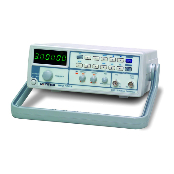
Synthesized Function Generator
SFG-1000 Series
USER MANUAL
GW INSTEK PART NO. 82FG-10030MA1
Visit us at www.TestEquipmentDepot.com
1sO-900, CERTIFIED MANUFACTURER
99 Washington Street
Melrose, MA 02176
Phone 781-665-1400
Toll Free 1-800-517-8431
Ii!!!
1n1
ST EK
Table of
Contents
Previous
Page
Next
Page
1
2
3
4
5
Advertisement
Chapters
Table of Contents
3
Etting Started
8
Ine/Square/Triangle Wave
19
Tl Output
25
Table of Contents
Need help?
Do you have a question about the SFG-1000 Series and is the answer not in the manual?
Ask a question
Questions and answers
Related Manuals for GW Instek SFG-1000 Series
Inverter GW Instek SFG-1003 User Manual
Synthesized function generator (41 pages)
Inverter GW Instek SFG-1013 User Manual
Synthesized function generator (41 pages)
Inverter GW Instek AFG-2225 User Manual
Arbitrary function generator (301 pages)
Inverter GW Instek GFG-80150 Manual
Function generator (48 pages)
Inverter GW Instek AFG-2225 Quick Start Manual
Arbitary function generator (56 pages)
Inverter GW Instek AFG-3000 Series Quick Start Manual
Arbitrary function generator (30 pages)
Inverter GW Instek AFG-2000 Series User Manual
Afg-2000 series arbitrary function generator (145 pages)
Inverter GW Instek MFG-2000 Series Quick Start Manual
Multi-channel function generator (85 pages)
Inverter GW Instek MFG-2000 Series User Manual
Multi-channel function generator (409 pages)
Inverter GW Instek AFG-3022 User Manual
Arbitrary function generator (422 pages)
Inverter GW Instek AFG-2225 Quick Start Manual
Arbitrary function generator (56 pages)
Inverter GW Instek AFG-3021 User Manual
Arbitrary function generator (424 pages)
Inverter GW Instek GFG-8020H User Manual
Digital function generator (26 pages)
Inverter GW Instek GFG-3015 User Manual
Function generator (55 pages)
Inverter GW Instek USG-LF44 User Manual
Signal and tracking generator usg series (51 pages)
Inverter GW Instek AFG-2000 Series User Manual
Arbitrary function generator (145 pages)
This manual is also suitable for:
Sfg-1003
Sfg-1013
Table of Contents
Print
Rename the bookmark
Delete bookmark?
Delete from my manuals?
Login
Sign In
OR
Sign in with Facebook
Sign in with Google
Upload manual
Upload from disk
Upload from URL


Need help?
Do you have a question about the SFG-1000 Series and is the answer not in the manual?
Questions and answers