
Subscribe to Our Youtube Channel
Related Manuals for GW Instek GFG-3015


Summary of Contents for GW Instek GFG-3015
-
Page 1: User Manual
Function Generator GFG-3015 USER MANUAL GW INSTEK PART NO. 82FG-30150MC1 ISO-9001 CERTIFIED MANUFACTURER... - Page 2 This manual contains proprietary information, which is protected by copyrights. All rights are reserved. No part of this manual may be photocopied, reproduced or translated to another language without prior written consent of Good Will company. The information in this manual was correct at the time of printing. However, Good Will continues to improve products and reserves the rights to change specification, equipment, and maintenance procedures at any time without notice.
-
Page 3: Table Of Contents
1. Precautions........................2 2. Product Introduction ......................5 3. Features ..........................6 4. Specifications ........................7 5. Front and Rear Panels ....................10 6. Operation ........................18 6.1 The First Step Setup For Instrument ..............18 6.2 The Setup of Output Function ................18 6.3 The Setup of Frequency ..................18 6.4 The Setup of Amplitude..................19 6.5 The Setup of Offset....................19 6.6 The Setup of Duty ....................20... -
Page 5: Ec Declaration Of Conformity
No. 69, Lushan Road, Suzhou New District Jiangsu, China declares that the below mentioned product GFG-3015 is herewith confirmed to comply with the requirements set out in the Council Directive on the Approximation of the Law of Member States relating to Electromagnetic Compatibility (2004/108/EC) and Low Voltage Equipment Directive (73/23/EEC &... -
Page 6: Precautions
If the instrument has to be opened or adjusted under some unavoidable conditions, and to be managed by a technician who is familiar with GFG-3015. Once there is any abnormality, please contact our company or our distributor near you. - Page 7 WARNING conductor must be connected to ground. GFG-3015 can be operated only with an earth grounded AC power cord that connects the case and ground well. This is to protect the user and the instrument from the risk of shock hazard.
- Page 8 For measurements performed on circuits not directly connected to Mains. (9) Place GFG-3015 in a location with a suitable environment as stated above free from dust, direct exposition of sunlight, and strong effect of magnetic fields. (10) For United Kingdom...
-
Page 9: Product Introduction
Time interval, Pulse wide, direct display and direct connect with CPU system. GFG-3015 uses this Chip to read output frequency value at any time. Then CPU will modify the correct value of D/A converter immediately according to this value, so that the user can get a high accuracy frequency from GFG-3015 Function Generator. -
Page 10: Features
3. Features GFG-3015 is a functional Function generator that applies Frequency feedback control system technique and can generate high frequency accuracy with high resolution. Its main signal source can generate waveforms including sine wave, square wave, triangle wave, and ramp wave. -
Page 11: Specifications
>1Vp-p open circuit ≤0.5%(-46dBc) From 10Hz~100kHz Distortion Sine ≤-30dBc To 15MHz (Spec. applied form 1Vpp to 10Vpp) ±1% of period + 3ns Asymmetry Square Rise or Fall Time <18nSec Triangle and Ramp Linearity Error <1% of full scale output at 100Hz GFG-3015... - Page 12 0.01Hz ~ 10kHz(INT) DC~1MHz(EXT) Frequency Rate Carries -3dB <100Hz to >5MHz Bandwidth External Sensitivity ≤10Vpp for 100% modulation Frequency Modulation Deviation 0~±15% Modulation 0.01Hz ~ 10kHz(INT) DC ~ 50kHz(EXT) Frequency Rate External Sensitivity ≤5Vpp for 15% deviation p. 8 GFG-3015...
- Page 13 1M // 150pF ≤35mVrms(5Hz~100MHz); Sensitivity ≤45mVrms(100MHz~150MHz) Interface RS232 Accessories GTL-101 × 2, Instruction Manual × 1, Power cord × 1 Power Source 115/ 230V AC ±15%, 50/60Hz Dimensions 290 (W) × 142 (H) × 346 (D) mm Weight Approx. 5kg GFG-3015...
-
Page 14: Front And Rear Panels
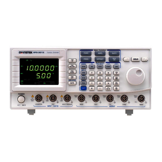
5. Front and Rear Panels Front Panel p. 10 GFG-3015... - Page 15 Secondary Function mode. INT/EXT Key is to set Rate of Modulation, Sweep or Trigger RATE entry mode and choose the signal source of Modulation, Sweep or Trigger. If want to set to signal, must use Secondary Functions mode. GFG-3015 p.11...
- Page 16 For example, you can use dBm and Vpp to set the output amplitude. They can be used to set frequency (MHz, kHz, Hz), OFFSET, and PHASE, etc. In STOR or RECL modes, they are used as ‘Enter’. p. 12 GFG-3015...
- Page 17 The STOP LED light on indicated that the value of display was Stop frequency of sweep function right now. The CF LED light on indicated that the value of display was center frequency of sweep function right now. GFG-3015 p.13...
- Page 18 The Sine, Triangle and Square LED light on indicated that according Modulation source waveform. The EXT LED lights on to indicate the external sweep or modulation signal source. The ON/OFF LED lights on to indicate that the sweep or modulation function is enabled. p. 14 GFG-3015...
- Page 19 This is the BNC connector for VCF signal input. 10V± 1V The frequency variation width index is 100:1 when Impedance is input. Input is 10kΩ. Input BNC This is the BNC connector for external counter signal input. Counter Impedance 1M // 150pF The Input GFG-3015 p.15...
-
Page 20: Rear Panel
Rear Panel p. 16 GFG-3015... - Page 21 50/60Hz. Line Voltage Selector This switch can choose the current line voltage between 115V and 230V RS232 connector This is the port of serial RS232 interface. The DCE and Baud rate is among 300 ~ 19.2k. GFG-3015 p.17...
-
Page 22: Operation
1.5001kHz ~ 15.0000kHz…(0.1Hz); Frequency 150.01Hz ~ 1.50000kHz…(10mHz) Resolution 15.01Hz ~ 150.00Hz…(10mHz) 1.51Hz ~ 15.00Hz…(10mHz) 0.01Hz ~ 1.50Hz…(10mHz) Example of the Setup Frequency 1. To set frequency at 250Hz Press first, then key in and press FREQ Hz/Vpp p. 18 GFG-3015... -
Page 23: The Setup Of Amplitude
Then turn the Rotate Knob clockwise until the digit become to “ 2 ”. The input limit : (1) Amplitude should be among 0.01 ~ 10Vpp. (2) Offset should be among ±5Vpp. (3) AMPL + |2 × OFFSET| ≤ 10Vpp. GFG-3015 p.19... -
Page 24: The Setup Of Duty
Press any button from DEG/% MHz/dB kHz/Vms Hz/Vpp to complete the setting. Example of the Setup RECALL To retrieve a parameters from the RAM of group #6. RECL Press SHIFT first, then key in and press Hz/Vpp STOR p. 20 GFG-3015... -
Page 25: The Shift Key And Function Keys
GATE 6.10 Setup of LIN or LOG Sweep GFG-3015 can adopt frequency to sweep its function output for triangle and ramp waves. The type of sweep can be set as linear or log sweep. Select a main waveform by using button. - Page 26 Note: 1. Please refer to the setup of LIN and LOG Sweep as the sample below. 2. Because all frequency range (0.01Hz ~ 15MHz) of GFG-3015 are composed of 8 frequency ranges (The details as below), So the value of start and stop frequency must be at the same sweep range.
- Page 27 LOG S Then press to select LOG sweep mode. SHIFT LIN S INT/EXT Press in sequence. RATE Hz/Vpp STOP Press in sequence. START KHz/Vrm STOP Press in sequence. START SHIFT KHz/Vrm SWP CF Press in sequence. DEG/% GFG-3015 p.23...
- Page 28 Error message for Sweep Function Because all frequency range (0.01Hz ~ 15MHz) of GFG-3015 are composed of 8 frequency ranges, So the Sweep function has specific restriction on the start and stop frequency. If the value of start and stop frequency not at the same sweep range, then the instrument will show the message to user.
-
Page 29: Setup Of Am Modulation
3. It won’t make any change on execution and result by taking different step sequence. 4. GFG-3015 can output waveform synchronizing with its modulation function. In the example of setting up amplitude modulation, the Modulation output terminal will output the waveform of sine at 100Hz. -
Page 30: Setup Of Fm Modulation
SHIFT INT/EXT Press RATE to set up modulation RATE value (Range 0.01Hz ~ 10kHz). SOURCE To select the modulation signal by pressing SPAN buttons. SHIFT GFG-3015 offers sine, square, and triangle (ramp) signals for internal modulation. p. 26 GFG-3015... - Page 31 MOD/ON to start performing frequency modulation. Note: 1. As all frequency range (0.01Hz ~ 15MHz) of GFG-3015 are composed of 8 frequency ranges (The details as below), When the main frequency in FM function is set, a reasonable Span must be considered.
-
Page 32: Setup Of Trigger
Duty of Internal trigger signal (Range 90%:10%:90%). Select the Trigger start Phase by pressing button and number keys. PHASE GFG-3015 offers -90º ~ +80º range for internal trigger mode. Press to start performing Trigger function. TRIG ON p. 28... - Page 33 It won’t make any change on execution and result by taking different step sequence. 4. The Trigger function of GFG-3015 must meet the important setting condition with the Main frequency higher than Trigger rate frequency! Example of the Setup of Trigger Function To set the following conditions: Main function: Sine Wave.
-
Page 34: Setup Of Gate And Burst
Figure (1) Figure (2) 6.14 Setup of GATE and BURST The GFG-3015 provides GATE or BURST function performed with different Trigger settings. If want to set to GATE or BURST function, just proceed some simple calculation and some Trigger setting. - Page 35 Press to select Triangle wave for main output. FUNC Press in sequence. AMPL Hz/Vpp Then press in sequence. FREQ KHz/Vrm Press to set Trigger Type to Multi-Trigger. SIGL/MUT Press to select the source from internal signal. TRIG EXT GFG-3015 p.31...
-
Page 36: Setup Of External Counter
2. Use suitable external signal to set the GATE function you need. Figure (3) Figure (4) 6.15 Setup of External Counter The GFG-3015 provides a high performance external frequency counter and with 6 digits counter and up to 150MHz high frequency range with high resolution. INT/EXT... - Page 37 External source for Counter mode. SHIFT GATE Connect the testing signal with “Counter Input BNC connector”. INT/EXT Press to select the Gate time of you need. GATE The correct frequency will be displayed. (Parameter display Area (A)) GFG-3015 p.33...
-
Page 38: The Vcf Function
100 times. But that just appear in Same “Frequency variation Range”. Because whole frequency range (0.01Hz ~ 15MHz) of GFG-3015 is composed of 8 frequency range (The detail is as below). So User’s voltage just can control at same frequency range. -
Page 39: The Gcv Output Function
Basically, If user set any main frequency then It will get a relative voltage from instrument. But that just appear in same “Frequency Range”. Because whole frequency range (0.01Hz ~ 15MHz) of GFG-3015 are composed of 8 frequency range (The detail is as below). So the GCV output voltage (0.2 to 2V) just appear on each same frequency range. -
Page 40: The Ttl Signal Output Function
6.18 THE TTL Signal Output Function The GFG-3015 provides a compatible TTL level signal from TTL Output BNC connector. The frequency of TTL signal output depends on the main output frequency. If need to modify the frequency of the signal, please refer to the procedure of 6.3 The Setup of Frequency. - Page 41 Data Terminal Equipment. Figure 6.20.1 DB9 to DB9 wiring When the GFG-3015 is set up with a RS232 interface, please check the following points: Do not connect the output line of one DTE device to the output line of the other.
-
Page 42: Commands Syntax
Should return the Manufacturer, model number and firmware version in the following format: GW,GFG3015,V.1.00 If you do not receive a proper response from the GFG-3015, please check if the power is on, the RS232 configurations are the same on both sides, and all cable connections are active. - Page 43 Figure includes the Boolean parameter type Do not include the <, >, or | symbols when entering the actual value for a NOTE: parameter. :SOURce:SWEep:SPACing <NR1> Parameter T ype Space Figure 3-4: Command Header w ith Parameter Command Header with Parameter GFG-3015 p.39...
- Page 44 Command Characters The GFG-3015 is not sensitive to the command characters. You can enter commands in either uppercase or lowercase. You can precede any command with white space characters. You must, however, use at least one space between the parameter and the command header.
-
Page 45: The Commands Of Rs-232 Serial Interface
Numeric data Check the voltage of offset :OFFSet ? None Set the value of duty :DUTY <NR1> Numeric data Check the value of duty :DUTY ? None Set the waveform of :SOURce:WAVeform <NR1> <1>Sinusoid modulation mode <2>Triangle <3>Square GFG-3015 p.41... - Page 46 Set the value of sweep rate :SOURce:SWEep:RATe <NRf> Numeric data Check the value of sweep :SOURce:SWEep:RATe ? None rate Set the value of sweep SYM :SOURce:SWEep:SYM <NR1> Numeric data Check the value of sweep :SOURce:SWEep:SYM ? None p. 42 GFG-3015...
- Page 47 SYM Set the gate time of :SOURce:COUNter:GATe <NR1> <0>001sec counter <1>01sec <2>1sec <3>10sec Check the gate time of :SOURce:COUNter:GATe ? None counter Set the counter source :SOURce:COUNter:SOURce <NR1> <0> Internal <1> External Check the counter :SOURce:COUNter:SOURce ? source GFG-3015 p.43...
-
Page 48: The Examples Of The Communication Interface Software
#include <stdio.h> #include <windows.h> HANDLE InitCom (int Error_Value); char *Error_Message[6]={ "Error Create File\n", "Error SetCommTimeous\n", "Error SetCommState\n", "Error SetupComm\n", "Error GetCommState\n", "Error EscapeCommFunction\n" void main() char command_line[100]; char Receive_Data[100]; char Read_Machine_Number[10] ={"*IDN?\n"}; DWORD dwcommand_len=0,dwWritten=0,dwRead=0; i,error_value=0; HANDLE hComm; p. 44 GFG-3015... - Page 49 GENERIC_READ | GENERIC_WRITE, 0, NULL, OPEN_EXISTING,NULL, NULL ); if (hComm == INVALID_HANDLE_VALUE) printf("%s",Error_Message[0]); return FALSE; /*----------------- Timeout -------------------*/ CommTimeOuts.ReadIntervalTimeout = 1; CommTimeOuts.ReadTotalTimeoutMultiplier = 0; CommTimeOuts.ReadTotalTimeoutConstant = 1000; CommTimeOuts.WriteTotalTimeoutMultiplier = 0; CommTimeOuts.WriteTotalTimeoutConstant = 5000; if(!SetCommTimeouts(hComm, &CommTimeOuts )) printf("%s",Error_Message[1]); return FALSE; GFG-3015 p.45...
- Page 50 // number of bits/byte, 4-8 dcb.Parity = 0; // 0-4=no,odd,even,mark,space dcb.StopBits=0; // 0,1,2 = 1, 1.5, 2 if (!SetCommState(hComm, &dcb)) printf("%s",Error_Message[3]); return FALSE; /*---------------- Set In,Out Queue -----------*/ if(!SetupComm(hComm, 8196,8196)) printf("%s",Error_Message[4]); return FALSE; if (!EscapeCommFunction(hComm, SETDTR)) printf("%s",Error_Message[5]); return FALSE; return hComm; p. 46 GFG-3015...
-
Page 51: The Error Message Of Instrument
6.24 The Error message of instrument The operation of GFG-3015 is a whole digitizing operation user interface. Every parameter will be showing by numerically and every input value keyed in with numerical keys. So when key in the value to instrument, it might cause some mistake, now the GFG-3015 will show a corresponding error code on the Display a few seconds later for User to correct the data. -
Page 52: The Block Diagram And Description Of The System
7. The Block Diagram and Description of the System The block diagram of GFG-3015 consists of a micro processor unit (MPU), a Voltage control Frequency (VCF), many digital to analog converters (D/A) for corresponding block, a square and sine waveform Shaper, a modulation function generator, a Trigger signal generator, a Frequency Counter(GFC-9701), an output amplifier, an attenuator (ATT), and etc. - Page 53 MPU will set the frequency accordingly. (5) Description of every kind of Waveform The GFG-3015 provides many kinds of waveforms including Sine, Triangle, Square, Ramp and Pulse. Please refer to the following for details: 1. Triangle and Ramp Waveform...
- Page 54 (6) Amplitude and DC offset The Amplifier of GFG-3015 is similar to lineally multiplier (EL4451). The amplitude of this amplifier varies with the different control voltage. The control voltage comes from the Amplitude of the D/A converter. The MPU puts a specific value to the D/A converter which will generate a corresponding voltage to main output Amplifier, from which, user will get different output amplitude.
- Page 55 GW has designed its own full function counter chip, GFC-9701, with high frequency test range for the system. The counter has the internal and external counter mode for GFG-3015. The most important function for the internal counter mode is to show the main frequency (VCF) on the display.
Need help?
Do you have a question about the GFG-3015 and is the answer not in the manual?
Questions and answers