Table of Contents
Advertisement
Advertisement
Table of Contents

Related Manuals for Leica HDS6000


Summary of Contents for Leica HDS6000
- Page 1 Leica HDS6000 User Manual Version 1.1 English...
- Page 2 The type and the serial number of your product are indicated on the type plate. identification Enter the model and serial number in your manual and always refer to this informa- tion when you need to contact your agency or Leica Geosystems authorized service workshop. Type: _______________ Serial No.:...
- Page 3 Trademarks • Windows is a registered trademark of Microsoft Corporation • Bluetooth is a registered trademark of Bluetooth SIG, Inc All other trademarks are the property of their respective owners. Introduction HDS6000...
-
Page 4: Table Of Contents
Description of the System Instrument Components Cabling 1.2.1 Operate the HDS6000 with the Battery 1.2.2 Operate the HDS6000 with the Battery Charger (AC power supply) 1.2.3 Operate the HDS6000 with the External Battery Field of View (FOV) Cyclone Software Suite... - Page 5 Data Management Settings Updating the Firmware Connections 3.10 Network 3.10.1 Connecting the HDS6000 by Cable to the Network 3.10.2 Connecting the HDS6000 to a Notebook 3.11 Operating the HDS6000 using a Web Browser 3.12 HDS6000 and WLAN Connection Troubleshooting Care and Transport Check &...
- Page 6 HDS6000 Table of Contents Safety Directions General Description Intended Use Limits of Use Responsibilities International Warranty, Software Licence Agreement Hazards of Use Laser Classification Scanner, Visible Laser Electromagnetic Compatibility EMC FCC Statement, Applicable in U.S. Technical Data General Technical Data of the Instrument...
-
Page 7: Description Of The System
("battery" will be used) c) Tribach d) Tripod e) Cleaning kit Carrying straps g) Transport box for power supply h) Transport box for HDS6000 Ethernet cable HDS6000 power supply cable k) Charging cable (optional) Battery charger power cable m) KNL-24 battery charger/AC power supply ("battery charger"... - Page 8 HDS6000 Description of the System Hardware options • External Battery TRAPP-15-24 • HDS6000 scan targets and target accessories • Dolly Transport box for power supply a) Battery charger b) Battery c) Charging cradle d) Charging cable e) Battery charger power cable;...
- Page 9 Transport box for HDS6000 a) HDS6000 b) Manuals c) Carrying straps d) HDS6000 power supply cable e) Ethernet cable HDS6000_007a Description of the System HDS6000...
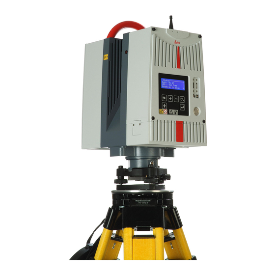
- Page 10 HDS6000 Description of the System HDS6000 a) Handle b) Mirror (Laser exit) c) Laser active light, flashes while scanning d) Circular level e) Antenna Display g) USB Connectors, P1, P2 h) Lemo Connectors (not supported), P3, P4 ON/OFF button Keyboard...
- Page 11 Charging cradle c) Battery status indicators d) Connector for power supply e) Power indicator LED Error LED g) SupD-9 plug; connects battery and charging cradle HDS6000_003 Use the SupD-9 plug only for connecting to the battery. Description of the System HDS6000...
- Page 12 HDS6000 Description of the System Battery charger a) Air inlet b) Mains switch c) Fuse d) Mains plug e) Fan Fuse g) Green LED, showing battery is fully charged h) Yellow LED 2 4 V 6 ,3 Power indicator LED...
- Page 13 External battery TRAPP-15-24 a) Main switch b) Battery status indicators c) Output additional voltage, not used d) Fuse for additional voltage, 3.15 AM e) Main output Fuse for main output, 6.3 AFF HDS6000_067 Description of the System HDS6000...
-
Page 14: Cabling
HDS6000 Description of the System Cabling 1.2.1 Operate the HDS6000 with the Battery 1. Hold the battery with both Change the battery hands and press the fixing clips. 2. Pull the battery carefully downwards. HDS6000_021 A battery should always be attached to ensure the optimum weight balance for the... - Page 15 +10°C and +20°C. • It is normal for the battery to become warm during charging. Using the chargers recommended by Leica Geosystems, it is not possible to charge the battery if the temperature is too high. Description of the System...
- Page 16 HDS6000 Description of the System Operation/Discharging • The batteries can be operated from 0°C to 40°C / +32°F to °104°F. • Low operating temperatures reduce the capacity that can be drawn; very high operating temperatures reduce the service life of the battery.
- Page 17 7. After charging the battery, turn off the battery charger. 8. Disconnect the cables. 24 V 6, 3 HDS6000_004 Charging of the battery takes approximately 1.5 hours. Description of the System HDS6000...
- Page 18 HDS6000 Description of the System Understand the charging cradle’s LEDs: a) Battery status indicators b) Power indicator LED c) Error LED HDS6000_006 Battery status • If all four LEDs flash continuously then there is no battery in indicators the charging cradle.
- Page 19 Error LED The red LED illuminates if there is a fault in the electricity supply. Please refer to "HDS6000 Battery" in "4 Trouble-shooting". Power indicator The green power indicator LED illuminates if the charging cradle is under voltage. Danger To avoid electrical shock, outdoor use of the battery charger is not permitted.
-
Page 20: Operate The Hds6000 With The Battery Charger (Ac Power Supply)
Battery charger power cable HDS6000_005 1. Verify that the battery charger is off. 2. Connect the battery charger power cable. 3. Connect the HDS6000 and the battery charger with the HDS6000 power supply cable. 4. Turn on the battery charger. - Page 21 Caution To avoid connector damage, turn off the battery charger before connecting it to the HDS6000. Danger To avoid electrical shock, outdoor use of the battery charger is not permitted. Precautions: Use the battery charger in dry indoor environments only.
-
Page 22: Operate The Hds6000 With The External Battery
HDS6000 Description of the System 1.2.3 Operate the HDS6000 with the External Battery Understand the a b c external battery condition indica- tors a) Green LED b) Yellow LED c) Red LED HDS6000_068 If the external battery is turned on and not connected to the scanner: Green LED External battery is fully charged and ready to use. - Page 23 6. A yellow battery charger LED means that the battery is being charged. 7. A green battery charger LED means that the battery is fully charged. 8. After charging the battery, turn off the HDS6000_063 battery charger. 9. Disconnect the charging cable. Description of the System HDS6000...
- Page 24 • The period of use ranges from 2.5 to 6 hours and depends on the electrical load, external battery temperature, and usage cycles. • After 200 to 300 cycles, consider contacting Leica Geosystems or your distributor to replace the battery.
- Page 25 To avoid connector damage, turn off the external battery before connecting it to the HDS6000. Precautions: 1. Verify that the external battery is off. 2. Connect the HDS6000 power supply cable to the HDS6000 and the external battery. Description of the System HDS6000...
- Page 26 HDS6000 Description of the System 3. Turn on the external battery. • A red external battery LED means that the external battery is empty and must be recharged immediately after finishing the current scan. If the external battery is further discharged, it turns off automatically without further warning.
-
Page 27: Field Of View (Fov)
Field of View (FOV) Field of view The HDS6000 has a rotating mirror system that covers a 360 x 310 degree field of view. HDS6000_008 Description of the System HDS6000... -
Page 28: Hds Cyclone Software Suite
Cyclone Software Suite Cyclone General Leica Geosystems HDS software modules provide point cloud users with the widest set of work process options for 3D laser scanning projects in engineering, surveying, construction and related applications. The Software consist of five packages: Cyclone •... - Page 29 • Download: Cyclone Principles Software, as well as important Support documentation, can be down- loaded from the Leica Geosystems HDS Website (http://www.leica-geosystems.com/hds/en/lgs_27048.htm). The User must create an account before the download section is accessible. • Installation: You must use a Windows account with administrator privileges to install or...
- Page 30 HDS6000 Description of the System Windows 2000 users: Cyclone , CloudWorx for AutoCAD, or CloudWorx for Intergraph Smart- Plant® Review fails to launch with an "entry point HeapSetInformation" error message after installing or upgrading, A) install Windows 2000 Service Pack 3 or Service Pack 4 with all avail-...
-
Page 31: Setting Up The Instrument
It is always recommended to shield the instrument from direct sunlight and avoid uneven temperatures around the instrument. A battery should always be attached to ensure the optimum weight balance for the HDS6000. Setting Up the Instrument HDS6000... -
Page 32: Scanner Setup On Tripod
HDS6000 Setting Up the Instrument Scanner Setup on Tripod Setup step-by-step HDS6000_009 Step Description Shield the instrument from direct sunlight and avoid uneven temperatures around the instrument. - Page 33 When placing the instrument on the tribrach, align the legs of the scanner’s table stand with the foot screws of the tribrach. Setting Up the Instrument HDS6000...
-
Page 34: Setup The Hds6000 Over A Benchmark
Setup the HDS6000 Over a Benchmark Description Geo-referencing of the HDS6000 is established by setting up over a known or assumed control point, with optional target extraction to set the azimuth direction, and establishing a local or global coordinate system. - Page 35 Shield the instrument from direct sunlight and avoid uneven temperatures around the instrument. Extend the tripod legs to allow for a comfortable working posture. Position the tripod approximately over the marked ground point. Fasten the tribrach onto the tripod. Setting Up the Instrument HDS6000...
- Page 36 Place the instrument on the tribrach and secure it with the tribrach’s locking knob. Make sure that the instrument is levelled by checking the built-in circular level. Cyclone Please see also the "Scanning with HDS6000" section in the docu- mentation for more information.
-
Page 37: Instrument Height
The instrument height entered in is automatically computed and reduced to its vertical value. Take care to use a 1:1 measure, not a special tape that is scaled differently (used for common surveying instruments). HDS6000_075 Setting Up the Instrument HDS6000... -
Page 38: Setting Up The Instrument With The Dolly
HDS6000 Setting Up the Instrument Setting Up the Instrument with the Dolly 1. Unscrew the knobs in the middle of the Set up the tripod dolly. with the dolly 2. Position the legs into the seat. 3. Screw the knobs. - Page 39 Set the lock to the LOCKED position. The spread is limited to a 30 degree angle. • Unlock the legs, and then adjust their angle. Assemble the chain with the chain clips on the clamps. Setup step-by-step HDS6000_061 Setting Up the Instrument HDS6000...
- Page 40 HDS6000 Setting Up the Instrument Step Description Shield the instrument from direct sunlight and avoid uneven temperatures around the instrument. Extend the tripod legs to allow for a comfortable working posture. Tighten the screws at the bottom of the legs.
-
Page 41: Preparing To Scan
Press and hold the ON/OFF button for minimum one second. dure • The display shows "DEVICE IS SWITCHING OFF". In the event of a system crash, press the On / Off button for at least 5 seconds. The system switches itself off. Preparing to Scan HDS6000... -
Page 42: Preparations
45 degrees (see following illus- tration). • The recommended distance of the targets to the scanner depends on the scan resolution. • Ensure that the HDS6000 is within the recommended distance of 5 to 17 meters / 16.4 to 55.8 ft to the targets. - Page 43 90° distance Medium 1 -10 m 15 m High 1 - 15 m 20 m Super High 1 - 20 m 25 m Ultra High 1 - 25 m 30 m Target distance <45° HDS6000_010 Preparing to Scan HDS6000...
- Page 44 Specified range accuracy is guaranteed for a minimum scanning distance of 1 meter / distances 3.28 ft; however, the HDS6000 can measure shorter distances. When setting up the HDS6000, verify that no objects are within the minimum meas- urable scanning distance. The HDS6000 has a range monitoring function which ensures the automatic deactivation of the laser beam as soon as an object (for example a person) is detected within the monitored area.
- Page 45 "LASER: OFF" is displayed in the Scan Control status bar. The user has two possibilities. 1. Remove all objects within < 0.3 m from the HDS6000 and start the scan once again. 2. Choose the option CLOSE and start the scan once again. The monitored range is now hardly greater than the housing of the HDS6000.
-
Page 46: Ambient Conditions
• If some objects are scanned against the sunlight or a bright spotlight, the optical receiver of the HDS6000 can be dazzled so heavily that in this area no measured data is recorded. A "black hole" appears in the reflectance... - Page 47 Precaution: Warm up / cool down the HDS6000. • To avoid damages of the electronics, the HDS6000 switches off when the upper temperature limit is exceeded. Precaution: Cool down the HDS6000 in a cold place. •...
- Page 48 Others Keep field notes containing: • Target positions relative to the HDS6000. • Position of the HDS6000 within the measured area (such as the factory or shed plan). Cyclone -SCAN Cyclone -SCAN software controls scanning operations with the HDS6000 and allows point cloud visualization and measurement.
-
Page 49: Hds6000 Controls
HDS6000 Controls 3.4.1 HDS6000 Control Buttons HDS6000 Control Select a main menu. Buttons Select a sub-menu. Increase a parameter. Reduce a parameter. Confirm your selection. Start/stop a scan; direct access to the scan menu. Preparing to Scan HDS6000... -
Page 50: Menu Control
When a appears in the bottom line you can page through the submenu using You can change values and parameters using - Info - - - - - - - - - - - Leica 01.09.2008 12:00:00 No 729/050811 IP 172.20.1.125... - Page 51 • Manual operation • Settings • Firmwareupdate = Settings = = = = = = = = = Date Time Language Press once more for five seconds to return to the main menu. Preparing to Scan HDS6000...
- Page 52 HDS6000 Preparing to Scan Info The main menu Info appears after system start-up. 01.09.2008 12:00:00 No 729/050811 IP 172.20.1.125 Ver 7.3.0.1796-305 HDS6000 Hard Im1.0 P1 3.0 P Content of Meaning Additional information display 01.09.2008 Date and time display The current date is set under 12:00:00 Settings/Date.
- Page 53 Additional information display Ver 7.3.0.1796- Firmware version The firmware can be updated under Firmware Update. HDS6000 Model designation Hard 1.0 Im Hardware implementa- tion Status - Status - - - - - - - - - - - - - - - -...
- Page 54 HDS6000 Preparing to Scan Content of display Meaning Batt: 71% AC Power supply status - AC No battery connected; power supply by battery charger or external battery. XX % AC Battery connected, battery charge state; power supply by battery charger active.
- Page 55 Scanning process cannot be started. Error PWRCTRL Scanning process cannot be started. Temp low Scanning process cannot be started, warm up the HDS6000. Temp high Scanning process cannot be started, cool down the HDS6000. Batt empty Empty battery, replace battery.
- Page 56 Preparing to Scan Tilt Sensor - Tilt Sensor - - - - - - - - - - - X: 0.0000 Y: 0.0000 Levelling indicator of the HDS6000. For further information about levelling the HDS6000 see "2 Setting Up the Instru- ment".
-
Page 57: Scanning
- Scanning - - - - - - - - - - - - Medium < changes from any menu directly High power into the scanning menu. for paging through further V 0 - 360 settings. H from 0.0 < = Parameters can be set using H to 182.0 Preparing to Scan HDS6000... - Page 58 Lines 20’000 10’000 5’000 2’500 Data file size ca. 2’400 ca. 800 MB ca. 200 MB ca. 50 MB ca. 3 MB for HDS6000, compressed Duration of 26 min 6 min 3 min 1 min 0 min scan 40 sec...
- Page 59 V 0 - 360: Definition of the vertical scan range (Selection). The following ranges are predefined in this submenu: Full 0° - 360° No Top 25° - 160° / 200° - 335° HDS6000_011 HDS6000_012 Preparing to Scan HDS6000...
- Page 60 HDS6000 Preparing to Scan Visible 25° - 335° Left 25° - 180° HDS6000_013 HDS6000_014 Right 180° - 335° Top 100° - 260° HDS6000_015 HDS6000_016...
- Page 61 The first value is the start position. Use to change to the second value (end posi- tion). Press to increase/decrease the values by 5°. For example: V 45 - 135 HDS6000_017 Press again to return to the predefined vertical scan ranges. Preparing to Scan HDS6000...
- Page 62 Turn the HDS6000 horizontally by hand into the desired start position. rately Press to confirm the position. H up to 180: Turn the HDS6000 horizontally by hand into the desired end position. Press to confirm the position. Press to start the scanning process.
-
Page 63: Data Management
The supported file systems are FAT32, ext2 and ext3. 1. Connect the external hard drive by USB to the HDS6000. 2. Switch on the external hard drive. 3. Select Copy or Move from the submenu. -
Page 64: Settings
• WLAN • Date • Netmask The HDS6000 must be restarted after a change of settings. to page through the submenus. The various settings are explained in the following sections. Language The supported languages are German, = Settings = = = = = = = = = English, French, Portuguese and 1. - Page 65 Change the value using 13:50:15 Move to the next value using Date = Settings = = = = = = = = = 4. Date Change the value using 01.08.06 Move to the next value using Preparing to Scan HDS6000...
- Page 66 = Settings = = = = = = = = = 6. DHCP Server Change the value using If the option yes is active, the DHCP server (HDS6000) can assign a dynamic IP address to the notebook. If the option no is active, then no IP address is assigned.
- Page 67 IP-Adress Manual assignment of an IP address for the HDS6000. = Settings = = = = = = = = = 7. IP Change the value using 172.20.0.251 Move to the next value using The displayed IP address is set out in the standard format.
- Page 68 = Settings = = = = = = = = = 10. HTTP Server Change the value using If the option yes is active, the HDS6000 can be operated directly from a web browser. This option is activated as default.
- Page 69 If the option yes is active, a Bluetooth connection can be established with a note- book/PDA. WLAN = Settings = = = = = = = = = 12. WLAN Change the value using If the option yes is active, a WLAN connection can be established with a note- book/PDA. Preparing to Scan HDS6000...
-
Page 70: Updating The Firmware
Check for new starts checking and installation of a firmware upgrade. Updating the firmware takes a few minutes. Do not turn off the HDS6000 during this operation! If the update is incomplete or installed incorrectly, the scanner can become inoperable. -
Page 71: Connections
WLAN interface; please see also chapter "3.12 HDS6000 and WLAN Connection". These interfaces allow external control of the HDS6000. As the HDS6000 has its own IP address, the device can also be controlled over the Internet as well as have its firmware updated. -
Page 72: Network
IP address. The HDS6000 supports DHCP (Dynamic Host Configuration Protocol). If the automatic reference to an IP address is set at the client (DHCP client), the HDS6000 can be included in any network without further configuration. -
Page 73: Connecting The Hds6000 By Cable To The Network
3.10.1 Connecting the HDS6000 by Cable to the Network Connecting by 1. Connect the HDS6000 by an ethernet cable to a hub/switch on the desired cable network. For information on ethernet interface, see "Ethernet connector" page 10. 2. Settings on the HDS6000: •... - Page 74 HDS6000 Preparing to Scan • Enter the IP address of the HDS6000 into your web browser. For example: http//172.20.0.251 • Confirm all alterations in your web browser.
-
Page 75: Connecting The Hds6000 To A Notebook
3.10.2 Connecting the HDS6000 to a Notebook Connection to the 1. Connect the HDS6000 to the notebook with a ethernet cable. The LAN connec- notebook tion should be automatically activated in the PC otherwise the attributes of the LAN connection could be shown by choosing network connections. Set a check mark at internet protocol (TCP/IP) and open the attributes. - Page 76 (blank) The scanning data files on the HDS6000’s hard drive are listed in their subfolders in the web browser/FTP client. When using the web browser a preview of every scan is shown. You can open the scanning data files or download them on to your...
-
Page 77: Operating The Hds6000 Using A Web Browser
3.11 Operating the HDS6000 using a Web Browser Start page The HDS6000 can be operated in a local network directly using a web browser. Enter the IP address of the HDS6000 into the address field of your web browser. Refer to IP address under "3.7 Settings". - Page 78 HDS6000 Preparing to Scan If the IP address is extended to show the menu’s shortcut commands, you can go directly to the desired page. For example: http//172.20.1.125/info Further shortcuts for menu points include: • /home • /debug • /camera/digital •...
- Page 79 Scan menu in Web For example: http://172.20.1.125/scan browser Preparing to Scan HDS6000...
- Page 80 Each subsequent scan is assigned to the created project and saved in the project. Scanner position Every scan is assigned a viewpoint (location of the HDS6000). If more than one scan is carried out from a single viewpoint then they are all assigned the same viewpoint.
- Page 81 Additional Entry of additional parameters. Start Scan Starts a scan using the selected settings. Preview Scan Starts a scan with Preview settings. Use default settings Restores the default settings of this menu. Preparing to Scan HDS6000...
-
Page 82: Hds6000 And Wlan Connection
HDS6000 Preparing to Scan 3.12 HDS6000 and WLAN Connection Area of use of The HDS6000 can be controlled with a WLAN interface as an alternative to the WLAN Ethernet cable connection. Settings on the • The ON/OFF button needs to be pressed for less then a second to turn on the HDS6000 instrument. - Page 83 "http://192.168.3.1" In WLAN mode the general IP address 192.168.3.1 is used instead of the unique scanner IP address. Further details of WLAN connection to the HDS6000 with a PDA can be found in the download area (http://www.leica-geosystems.com/hds/en/lgs_27048.htm). Preparing to Scan...
-
Page 84: Troubleshooting
HDS6000. Cyclone reports that the Temperature is too Leave the HDS6000 temperature is too high. high. powered. Wait until the active cooling in the scanner stops before resuming scan- ning. - Page 85 Problem Possible Cause(s) Suggested Remedies When switching on the Capacity of battery is Recharge or change battery. HDS6000 or starting a scan, too low. the battery switches off automatically. When switching on the Battery charger is Check the function of the HDS6000 or starting a scan, defective.
- Page 86 HDS6000 Troubleshooting Problem Possible Cause(s) Suggested Remedies Damaged cable. Examine the cabling and pay attention to damages, which e.g. can cause loose contacts or short circuits. Defective circuits need to be replaced. Only use supplied power cords! Battery is used up.
-
Page 87: Care And Transport
Units that are exposed to high mechanical forces, e.g. through frequent transport or rough handling, it is recommended to carry out a check and adjust twice a year by the manufacturer respectively just after such a high stress exposure. Care and Transport HDS6000... -
Page 88: Transport
Always carry the product in its transport container and secure it. Shipping When transporting the product by rail, air or sea, always use the complete original Leica Geosystems packaging, transport container and cardboard box, or its equiva- lent, to protect against shock and vibration. Shipping, transport... -
Page 89: Storage
• Remove batteries from the product and the charger before storing. • After storage, recharge batteries before using. • Protect batteries from damp and wetness. Wet or damp batteries must be dried before storing or use. Care and Transport HDS6000... -
Page 90: Cleaning And Drying
HDS6000 Care and Transport Cleaning and Drying Product and acces- • Use only a clean, soft, lint-free cloth for cleaning or use lens paper (e.g. for sories cleaning camera lenses). If necessary, moisten the cloth with water or pure alcohol. Do not use other liquids; these may attack the polymer components. -
Page 91: Window Cleaning Procedure
Window Cleaning Procedure General The HDS6000 scanning window must be kept clean. The instructions must be followed as described in this chapter to clean the scanner mirror. Warning Direct intrabeam viewing is always hazardous. Precautions: Before cleaning windows, ensure the instrument is switched off. - Page 92 HDS6000 Care and Transport Cleaning of the Soiling of the pane can cause extreme measurement errors and therefore useless optics data! Precautions: Caution All soiling that is visible on the glass pane has to be removed, except for single small dust particles that adhere inevitably.
-
Page 93: Adjustment Of The Circular Level
The bubble must be centered. If it extends beyond the circle, use an allen key to center it with the adjustment screws. Turn the instrument slowly 200 gon (180°). Repeat the adjustment procedure if the bubble does not stay centered. After the adjustment, no screw shall be loose. Care and Transport HDS6000... - Page 94 HDS6000 Care and Transport On the tribrach step-by-step HDS6000_070 Step Description Level up the tribrach together with the instrument in advance using the re- level funtionality in Cyclone , assuming that the instrument is correctly adjusted. Remove the instrument from the tribrach.
-
Page 95: Service Of The Tripod
Moderately tighten the allen screws (1) with the allen key supplied with the tripod. Tighten articulated joints just enough to keep the tripod legs open when lifting the tripod off the ground (2). Tighten the allen screws of the tripod legs (3). Care and Transport HDS6000... -
Page 96: Safety Directions
HDS6000 Safety Directions Safety Directions General Description Description The following directions should enable the person responsible for the product, and the person who actually uses the equipment, to anticipate and avoid operational hazards. The person responsible for the product must ensure that all users understand these... -
Page 97: Intended Use
Opening the product using tools, for example screwdriver, unless this is specifi- cally permitted for certain functions. • Modification or conversion of the product. • Use after misappropriation. • Use of products with obviously recognizable damages or defects. Safety Directions HDS6000... - Page 98 HDS6000 Safety Directions • Use with accessories from other manufacturers without the prior explicit approval of Leica Geosystems. • Inadequate safeguards at the surveying site, for example when measuring on roads. • Deliberate dazzling of third parties. • Controlling of machines, moving objects or similar monitoring application without additional control- and safety installations.
-
Page 99: Limits Of Use
Danger Local safety authorities and safety experts must be contacted before working in hazardous areas, or in close proximity to electrical installations or similar situations by the person in charge of the product. Safety Directions HDS6000... -
Page 100: Responsibilities
Manufacturer of Leica Geosystems AG, Heinrich-Wild-Strasse, CH-9435 Heerbrugg, Switzerland, here- the product inafter referred to as Leica Geosystems, is responsible for supplying the product, including the user manual and original accessories, in a completely safe condition. Manufacturers of The manufacturers of non Leica Geosystems accessories for the product are respon-... -
Page 101: International Warranty, Software Licence Agreement
Leica Geosystems. Such software is protected by copy- right and other laws and its use is defined and regulated by the Leica Geosystems Licence Agreement, which covers aspects such as, but not limited to, Scope of the Licence, Warranty, Intellectual Property Rights, Limitation of Liability, Exclusion of other Assurances, Governing Law and Place of Jurisdiction. - Page 102 You must not install or use the software unless you have read and accepted the terms and conditions of the Leica Geosystems Licence Agreement. Installation or use of the software or any part thereof, is deemed to be an acceptance of all the terms and conditions of such licence agreement.
-
Page 103: Hazards Of Use
Caution During the operation of the product there is a hazard of squeezing extremities or entanglement of hairs and/or clothes by rotating parts. Precautions: Keep a safe distance of the rotating parts. Safety Directions HDS6000... - Page 104 HDS6000 Safety Directions Danger Because of the risk of electrocution, it is very dangerous to use poles and extensions in the vicinity of electrical installations such as power cables or electrical railways. Precautions: Keep at a safe distance from electrical installations. If it is essential to work in this environment, first contact the safety authorities responsible for the electrical instal- lations and follow their instructions.
- Page 105 When setting-up the product, make sure that the accessories, for example tripod, tribrach, connecting cables, are correctly adapted, fitted, secured, and locked in posi- tion. Avoid subjecting the product to mechanical stress. Warning Only Leica Geosystems authorized service workshops are entitled to repair these products. Safety Directions HDS6000...
- Page 106 HDS6000 Safety Directions Warning Using a battery charger not recommended by Leica Geosystems can destroy the batteries. This can cause fire or explosions. Precautions: Only use chargers recommended by Leica Geosystems to charge the batteries. Danger The product is not designed for use under wet and severe conditions. If unit becomes wet it may cause you to receive an electric shock.
- Page 107 Warning Batteries not recommended by Leica Geosystems may be damaged if charged or discharged. They may burn and explode. Precautions: Only charge and discharge batteries recommended by Leica Geosystems. Danger Death or serious injury can occur if product is not connected to ground.
- Page 108 HDS6000 Safety Directions Warning Short circuited battery terminals can overheat and cause injury or fire, for example by storing or transporting in pockets if battery terminals come in contact with jewel- lery, keys, metallized paper or other metals. Precautions: Make sure that the battery terminals do not come into contact with metallic objects.
- Page 109 Only charge the battery in well-ventilated areas because it can produce explosive gases. Connect the battery to the battery charger only when the charger is turned off. Fire, smoking, and sparking near the battery are not allowed. Safety Directions HDS6000...
- Page 110 Always prevent access to the product by unauthorized personnel. Product specific treatment and waste management information can be downloaded from the Leica Geosystems home page at http://www.leica-geosystems.com/treatment or received from your Leica Geosys- tems dealer.
-
Page 111: Laser Classification Scanner, Visible Laser
Class 2 in the wavelength range from 400 nm to 700 nm. Description Value Maximum average radiant power 4.75 mW Maximum peak radiant power 30 mW Pulse duration 260 μs (max) Pulse repetition frequency 12.5 Hz (min) Beam divergence ± 0.11 mrad Safety Directions HDS6000... - Page 112 HDS6000 Safety Directions Warning For safety aspects direct intrabeam viewing should be considered always as hazardous. Precautions: Do not stare into the beam or direct it towards other people unnecessarily. These measures are also valid for the reflected beam. Warning...
- Page 113 6. Precautions should be taken to ensure that the laser beam is not unintentionally directed at mirror-like, specular surfaces for example mirrors, metal surfaces or windows. But, more importantly, at flat or concave mirror-like surfaces. Safety Directions HDS6000...
- Page 114 HDS6000 Safety Directions *) The hazard distance is the distance from the laser at which beam irradiance or radiant exposure equals the maximum permissible value to which personnel may be exposed without being exposed to a health risk. This hazard distance is 20 m / 66 ft.
- Page 115 Labelling Laser Aperture Laser Radiation Avoid direct eye exposure Class 3R Laser Product according to IEC 60825-1 ( 2001 - 08 ) Po ≤ 4.75 mW λ = 650 - 690 nm HDS6000_019 a) Laser beam Safety Directions HDS6000...
- Page 116 HDS6000 Safety Directions ..... S.No.: Art.No.: ..................................: ........Complies with 21 CFR 1040.10 and 1040.11 except for deviations pursuant to Laser Notice No.50, dated July 26,2001. This device complies with part 15 of the FCC Rules.
-
Page 117: Electromagnetic Compatibility Emc
Warning Electromagnetic radiation can cause disturbances in other equipment. Although the product meets the strict regulations and standards which are in force in this respect, Leica Geosystems cannot completely exclude the possibility that other equipment may be disturbed. Caution There is a risk that disturbances may be caused in other equipment if the product is... - Page 118 Precautions: Although the product meets in combination with radio or digital cellular phone devices recommended by Leica Geosystems the strict regulations and standards which are in force in this respect, Leica Geosystems cannot completely exclude the...
- Page 119 • Do not operate the product with radio or digital cellular phone devices in aircraft. • Do not operate the product with radio or digital cellular phone devices for long periods immediately next to your body. Safety Directions HDS6000...
-
Page 120: Fcc Statement, Applicable In U
Safety Directions FCC Statement, Applicable in U.S. Applicability The grayed paragraph below is only applicable for products of the HDS6000 System without radio, digital cellular phone devices or Bluetooth. Warning This equipment has been tested and found to comply with the limits for a Class B digital device, pursuant to part 15 of the FCC rules. - Page 121 Warning Changes or modifications not expressly approved by Leica Geosystems for compli- ance could void the user's authority to operate the equipment. Labelling ..... S.No.: Art.No.: HDS6000 ..................................: ........Complies with 21 CFR 1040.10 and 1040.11 except for deviations pursuant to Laser Notice No.50,...
- Page 122 Charging cradle INPUT: 24V, --- , 5A .... OUTPUT: 16,8V ---, 2.5A Leica Geosystems AG CH-9435 Heerbrugg Manufactured: ..,Made in Germany This device complies with part 15 of the FCC Rules. Operation is subject to the following two conditions:...
- Page 123 Type: Li-lon Battery Pack Art.No.: S.No.: 14.4V, --- , 4.8Ah .... Leica Geosystems AG CH-9435 Heerbrugg +60°C Manufactured: ..,Made in Germany This device complies with part 15 of the FCC Rules. Operation is subject to the following two conditions:...
- Page 124 KNL-24 battery INPUT: 100-240V, , 50/60Hz, 3.15A ..OUTPUT: 28V ---, 5.2A charger/AC power S.No.: Leica Geosystems AG ..supply CH-9435 Heerbrugg Manufactured: ..Made in Germany This device complies with part 15 of the FCC Rules. Operation is subject to the following two conditions:...
- Page 125 Labelling battery TRAPP-15-24 Non-Spillable Battery UN/ID Nr.: 2800 Class: Batteries, wet, non-spillable electric storage S.No.: Type: TRAPP-15-24 Art.No.: .... Non-Spillable Lead Battery 24V ---, 6.3A Leica Geosystems AG CH-9435 Heerbrugg Manufactured: ..Made in Germany HDS6000_073 Safety Directions HDS6000...
-
Page 126: Technical Data
HDS6000 Technical Data Technical Data General Technical Data of the Instrument Instrument Compact, phase-based, dual-axis sensing, ultra-high speed laser scanner with survey grade accuracy and full field-of-view. User interface Onboard touch panel, Notebook PC or PDA Scanner drive Servo motor... -
Page 127: System Performance
4 mm @ 90% albedo 5 mm @ 90% albedo 5 mm @ 18% albedo 6 mm @ 18% albedo At 1 m to 50 m range, one sigma Angle Angle Accuracy Horizontal 125 micro-radians Vertical 125 micro-radians Technical Data HDS6000... - Page 128 HDS6000 Technical Data Modeled surface Reflectivity Accuracy at 25 m Accuracy at 50 m precision δ 3 mm δ 7 mm 18% (dark grey) δ 2 mm δ 4 mm 90% (white) Target acquisition 2 mm standard deviation accuracy (algorithmic fit to planar HDS grey & white target) Dual-axis sensor •...
-
Page 129: Laser Scanning System
(vertical, horizontal) (full dome) Preview 1’250 25 sec Middle (4x) 5’000 1 min 40 sec High (8x) 10’000 3 min 22 sec Highest (16x) 20’000 6 min 44 sec Ultra High (32x) 40’000 26 min 40 sec Technical Data HDS6000... - Page 130 HDS6000 Technical Data Spot size: 3 mm at exit (based on Gaussian definition) + 0.22 mrad divergence; 8 mm @ 25 m; 14 mm @ 50 m Field-of-View (per Horizontal: 360º (maximum) Vertical: 310º (maximum) scan) Point spacing at Resolution...
- Page 131 Status indicators • 4-line alphanumeric display for laser status, system power and system status • 1 LED for Laser active status Level indicator External bubble; digital readout on touch panel or via laptop. Technical Data HDS6000...
-
Page 132: Electrical
HDS6000 Technical Data Electrical Batteries: 24 V DC power supply Power supply Battery charger: 90 - 260 V AC External Battery: 24 V DC Power consump- 50 W tion Battery: Integrated, Li-ion Battery type External battery: Sealed lead acid, non spillable Battery: up to 2.5 hours (room temperature) -
Page 133: Environmental
Environmental Environmental Temperature specifications Type Operating Storage temperature [°C] temperature [°C] HDS6000 0 to +40 -20 to +50 Battery charger 0 to +40 -20 to +50 Battery 0 to +40 0 to +50 External battery 0 to +50 0 to +40 Optimal operating temperature 10°C to 30°C... - Page 134 HDS6000 Technical Data Humidity Max 95 % non-condensing Lighting Fully operational from bright sunlight to complete darkness.
-
Page 135: Physical
240 x 260 x 300 Accessories Standard Accesso- • Scanner carrying case ries • Accessory carrying case • Additional battery • Battery charger • Charging cradle for battery • Charging/Power cable • A/C cable • Cleaning kit Cyclone • -SCAN software Technical Data HDS6000... - Page 136 Hardware Options • Notebook PC • Tablet PC • • External battery TRAPP-15-24 • HDS6000 scan targets and target accessories • Service agreement for HDS6000 • Extended warranty for Leica HDS6000 • Power cable Notebook PC for Component Minimum requirements...
- Page 137 Power Additional battery, two preferred Minimum requirements for modeling operations are different. Please refer to Cyclone datasheet for specifications, available at your Leica Geosystems dealer. Notebook PC does not record any data! Data can be transferred automatically after scan process.
- Page 138 HDS6000 Technical Data Cyclone –Scan Features: • ”Fly-around,“ pan & zoom, and freely rotate point clouds, intensity mapped clouds and models in 3D • Point cloud and 3D model Level of Detail (LOD) for fast visualization • Decimation of point clouds (Nth point) •...
- Page 139 • Environmental lighting • Save/restore views • Save screen image as image file • Undo/redo support • Scanner command scripting ** • Environmental lighting ** SmartScan Technology feature. Technical Data HDS6000...
-
Page 140: Wlan
HDS6000 Technical Data WLAN Standard: IEEE 802.11b/g WLAN technical Frequency band: 2412 MHz - 2462 MHz (channel 1 - 11) data Output power: <100 mW FCC IC: M4Y-AG623C... -
Page 141: Conformity To National Regulations
FCC Part 15 (applicable in US) Conformity to national regula- • Hereby, Leica Geosystems AG, declares that the HDS6000 is in compliance with tions the essential requirements and other relevant provisions of Directive 1999/5/EC. The declaration of conformity may be consulted at http://www.leica-geosys- tems.com/ce. - Page 142 HDS6000 Index Index Adjustment External battery ..........13, 22 Of circular level on instrument ....... 93 Of circular level on tribrach ......94 Field of View ............27 Battery ............7, 11 Grey and white tilt-and-turn targets ....42 Battery charger ..........12, 20 Battery status indicators .......
- Page 143 Operate the HDS6000 ........20 Targets ...............42 Optimum weight balance ........14 Temperature Operating .............133 Operation/Discharging ........16 Position the HDS6000 ......... 42 Permissible temperature .........15 Power supply ............8 Storage ............133 Tilt Sensor .............50, 56 Tripod, service of ..........95 Range ............... 129 Type of Connection ..........71...
- Page 144 Leica Geosystems AG Heinrich-Wild-Strasse CH-9435 Heerbrugg Switzerland Phone +41 71 727 31 31 www.leica-geosystems.com...
Need help?
Do you have a question about the HDS6000 and is the answer not in the manual?
Questions and answers