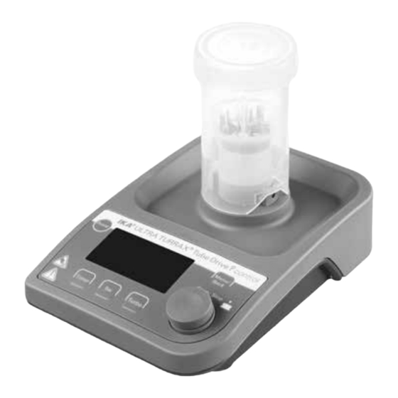
IKA ULTRA-TURRAX Tube Drive P control Manual
Hide thumbs
Also See for ULTRA-TURRAX Tube Drive P control:
- Operating instructions manual (56 pages)
Table of Contents
Advertisement
Quick Links
Advertisement
Table of Contents

Subscribe to Our Youtube Channel
Related Manuals for IKA ULTRA-TURRAX Tube Drive P control


Summary of Contents for IKA ULTRA-TURRAX Tube Drive P control
- Page 1 20000005139 UTTD P control_042018 IKA ULTRA -TURRAX Tube Drive P control ®...
-
Page 2: Table Of Contents
EN 61010-1, EN 61010-2-051, EN 61326-1, EN 60529 and EN ISO 12100. Safety instructions A copy of the complete EU Declaration of Conformity can be re- Unpacking quested at sales@ika.com. Correct use Useful facts Explanation of symbols Interfaces and outputs... -
Page 3: Safety Instructions
• The tube must only be attached and removed while the motor For your protection is stationary. • Read the operating instructions in full before starting up The IKA tubes must always be closed when the and follow the safety instructions. WARNING device is in operation. Switch off the device im- •... -
Page 4: Unpacking
Unpacking Correct use • Unpacking: • Use: - Please unpack the device carefully Application Volume Mode - In the case of any damage a fact report must be set immedi- Mixing 2 - 15 ml A, B, P1-P9, with Tube ST-20... ately (for post, rail or forwarder) Stirring 15 - 50 ml... -
Page 5: Useful Facts
Install the driver by running the setup file. Then connect the The device is suitable for use in residential areas and all other areas. IKA device through the USB data cable to the PC. The data The safety of the user cannot be guaranteed: communication is via a virtual COM port. -
Page 6: Commissioning
Pay attention to the ambient conditions listed in the “Technical or communications program these commands can be transmitted Data”. directly to the tube driver. The IKA software package, labworldsoft, If these conditions are met, the unit is ready provides a convenient tool for controlling tube driver and collecting... -
Page 7: Factory Setting
Then, the system check screen will be displayed for several seconds. Factory setting Symbols are shown on the screen, including the working mode set- ting, the target speed, the maximum rotation speed (rpm) and timer The device is supplied with following factory setting: maximum value etc. -
Page 8: Set Menu Parameters
Press the “Rotating/Pressing” knob (B). Setting menu parameters Turn the “Rotating/Pressing” knob (B) to select the “mode” item in mode P1 and P9 in submenu. 11.1 Operation mode Press the “Rotating/Pressing” knob (B) and enter desired menu program. The device can be operated in mode A, B and P1 to P9. The mode Turn the “Rotating/Pressing”... -
Page 9: Maximum Rotation Speed (Max Rpm)
Maximum rotation speed (max rpm) Timer maximum value (timer max) 11.3 11.4 The default “timer max” is 30 minutes in the device. User can The default setting “max rpm” is 6000 rpm in the device. User change the setting in 10 second intervals and up to 30 minutes can change the setting to the range of 400 to 6000 rpm in the in the main menu. -
Page 10: Set Working Parameters
Setting working parameters 12.3 Reverse (Rev) function When setting “Rev” value with the “Rotating/Pressing” knob (B), the 12.1 Target speed (target rpm) value can be set from 10 to 60 seconds where adjustment magni- tude is 1 second. Set “target rpm” within “rpm max” range in the working screen by rotating the “Rotating/Pressing”... -
Page 11: Error Codes
Error codes For cleaning disconnect the main plug. Only use cleansing agents which have been recommended by IKA. Any malfunction during operation may be identified by an error message on the display. -
Page 12: Accessories
For this, you should request the “Decontamination Certificate” from IKA, or use the download printout of it from the IKA web- site www.ika.com. If you require servicing, return the device in its original packag- ing. -
Page 13: Technical Data
Technical data Power supply unit Contamination level Input 100 ... 240 Overvoltage category Operation at a terrestrial max. 2000 50 / 60 altitude level Output Dimensions (W x D x H) 122 x 178 x 54 40 W.LPS without tube (limited power source) Weight Protection class...
Need help?
Do you have a question about the ULTRA-TURRAX Tube Drive P control and is the answer not in the manual?
Questions and answers