Advertisement
Quick Links
1.
General
1.1 SAFETY
2.
Assembly/disassembly of NAF-Triball
2.1 Welding-in NAF-Triball
2.2 NAF-Triball disassembly
2.3 NAF-Triball gland leakage
2.4 Screw torque specification (Nm)
3.
NAF-Triball: Spares for new CE-marked valves
888X5X-XXXX-XX resp. 888X6X-XXXX-XX or versions
thereof.
3.1 Spare parts and spare part kits
3.2 Ordering example
4.
Material specification
5
NAF-Triball Sampling valve 8886X4-XXXX-XX
Welding-in of the sampling valve
5.1
8886X4-XXXX-XX
5.2
Connection plate for sampling 8886X4-XXXX-XX
(previously 8887X4-XXXX)
1. General
Material specifications, various connections,
measurements etc. are to be found in catalogue sheet
Fk 25.622.
1.1 SAFETY
-
Assess all the risks to eliminate the risk of personal
injury and material damage. Read these instructions
thoroughly!
-
Always use the necessary protective equipment
and comply with applicable safety directives when
working with hazardous or hot/cold medium.
-
Never operate a valve without first ensuring that there
is no risk of crush injuries. The risk is highest with
automatic valves.
-
Take necessary safety precautions to prevent
unintentional manoeuvre - i.e to atmosphere.
-
Never dismantle a valve or part of a valve without
ensuring that the line is free of pressure and any
content.
-
Ball valves must always be dismantled in semi-open
position to avoid trapping pressure and medium.
-
Always check that the valve type and material is
suitable for its intended use. This applies especially to
highly oxidising and corrosive medium. Observe also
the risk of erosion and explosion as well as decaying
medium. If in doubt, always request a written
recommendation from NAF AB.
2 Assembly/disassembly of NAF-Triball
Please keep special attention to the following:
- To simplify assembly and avoid unnecessary strain
on the valve, i.e pipe forces, always check that the
pipes which the valve is to be welded between are
parallel and have the same centre line.
R
V
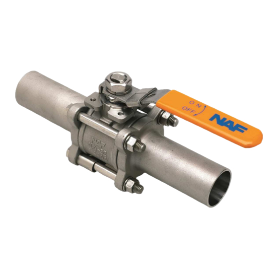
NAF-Triball ball valves
Maintenance and installation instructions
Spare parts list
- Remember that damage to the seat ring can cause
2.1 Welding-in NAF-Triball
- The version with long welding ends, NAF 8886X3-
- NAF-Triball with short welding ends, NAF 8886X1-
- The above applies on the condition that welding is
! After welding, both valves and connecting pipes should
2.2 NAF-Triball disassembly
1. Turn the ball to the open position. Remove one of the bolts
2. Remove the body section.
3. Refit the body section after the planned action is carried out
1
Fi 25.622(5)GB
Fi 25.622(5)GB
Fi 25.622(5)GB
leakage. Always use great care when disassembling
and reassembling the valves to avoid damage to the
rings from contamination.
XXXX-XX and NAF 8886X7-XXXX-XX do not need to
be disassembled before welding. Note that the ball
must be in the open position during welding. The
length of the welding ends is such that the temperature
will not damage the interior of the valve.
XXXX-XX and NAF 8886X4-XXXX-XX, must be
disassembled before welding. The valve body and its
seatrings must be removed as described below and
replaced with a suitable spacer, such as a body of the
same DN but without internal parts. Screw the end
pieces together and weld the unit into the pipe. After
welding, refit the complete valve body and tighten the
screws to specified torque, see below.
done professionally and in accordance with applicable
standards.
be cleaned from welding debris, scale etc.
Note: When re-assembling the valve, always use new
body seals in order to simplify assembly and
minimise risk for leakage.
(or stud) and release the other three.
and tighten the bolts (or studs), see required torque as per
table below. Use MoSo2 based grease to lubricate the threads
on the bolts.
08.09
08.09
Advertisement

Related Manuals for Flowserve NAF 8886 Series


Summary of Contents for Flowserve NAF 8886 Series
- Page 1 NAF-Triball ball valves Fi 25.622(5)GB Fi 25.622(5)GB Fi 25.622(5)GB Maintenance and installation instructions 08.09 08.09 Spare parts list General 1.1 SAFETY Assembly/disassembly of NAF-Triball 2.1 Welding-in NAF-Triball 2.2 NAF-Triball disassembly 2.3 NAF-Triball gland leakage 2.4 Screw torque specification (Nm) NAF-Triball: Spares for new CE-marked valves 888X5X-XXXX-XX resp.
- Page 2 2.3 NAF-Triball stem packing 1. If there is leakage through the stem packing, then retighten the gland nut until the leakage stops. 2. If the leakage continues the valve should be dismantled and the packing box exchanged. To facilitate dismantling and handling of valves in sizes DN 65-100 these valves are equipped with a support flange for the studs which are fitted into clea- rance holes in the top part of the body.
- Page 3 12A 12B Material specification Material specification Item No. Part Material Sleeve Lever EN1.4301 Gland, DN <= 50 EN1.4435 Gland, DN >= 65 EN1.4301 Washer EN1.4301 Box packing PTFE, Virgin O-ring Stem EN1.4435 Bearing washer PTFE Seat ring+ Body seal ring PTFE, MG1241 Seat ring+ Body seal ring Alloy 6 + PTFE (seal)
- Page 4 5 NAF-Triball Sampling valve 8886X4-XXXX-XX Connection plate for sampling 8886X4-XXXX-XX (previously 8887X4-XXXX) These valves are aimed to be welded-in to a pipe to simplify sampling without plugging the valve up-stream. The valves pipe adapter/end piece is designed in order to minimise the risk for plugging in the inlet up-stream.