
Related Manuals for Flowserve MASTER STATION IV EEP-SN4001


Summary of Contents for Flowserve MASTER STATION IV EEP-SN4001
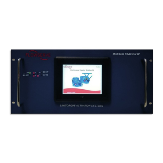
- Page 1 USER INSTRUCTIONS MASTER STATION IV: Installation EEP-SN4001 Operation Maintenance FCD LMENIM5010-00-AQ - 03/19 Experience In Motion...
- Page 2 Limitorque Master Station IV EEP-SN4001 FCD LMENIM5010-00-AQ – 03/19 ®...
-
Page 3: Table Of Contents
7.2.1 System Settings 7.2.2 Redundant Configuration 7.2.3 Change MOV Tags 7.2.4 User Administration 7.2.5 DCS Configuration 7.2.6 MOV Network Configuration 7.2.7 File Manager Diagnostics Main Menu Diagnostics Troubleshooting Guide Front Panel Indicators Network Status Screen Blank Display Network Communications flowserve.com... - Page 4 Limitorque Master Station IV EEP-SN4001 FCD LMENIM5010-00-AQ – 03/19 ® Figures Figure 1.1 - Introduction Figure 1.2 - Enter User Name Figure 1.3 - Login Figure 1.4 - Main Menu Figure 2.1 – MSIV Functional Flowchart Figure 4.1 – MSIV Rear Panel Electrical Connections Figure 4.2 –...
- Page 5 Table 7.8 – Function Code 06 First command message breakdown Table 7.9 – Function code 06 message breakdown Table 7.10 – Function code 06 message breakdown Table 7.11 – Function code 16 message breakdown Table 7.12 – Valid Command Register Operations flowserve.com...
-
Page 6: Introduction
Introduction 1.1 Overview The next generation master station is designed by Flowserve Limitorque specifically for use with the Limitorque line of electric actuators equipped with Modbus DDC. The Master Station IV (MSIV) acts as a single-source controller for up to 250 actuators. -
Page 7: Login
Touch the display to exit the screen saver mode. Figure 1.2 - Enter User Name Once the user name has been entered, the Enter Password screen will be displayed (Figure 1.3). NOTE: Each user name must have a unique password. Figure 1.3 - Login flowserve.com... -
Page 8: Main Menu
Limitorque Master Station IV EEP-SN4001 FCD LMENIM5010-00-AQ – 03/19 ® Passwords and user names are set via the User Administration menu, under System Configuration. The correct password entry for the respective user name will advance the screen to the Main Menu (Figure 1.4). -
Page 9: System Technical Data
Electromagnetic Compatibility (EMC) Compliance 7.1. EN 61326-1:2013 7.2. EN 55011:2009+A1(2010) Class A 7.3. EN 61000-4-2:2009 7.4. EN 61000-4-3:2006+A1(2008)+A2(2010) 7.5. EN 61000-4-4:2004+A1(2010) 7.6. EN 61000-4-5:2006 7.7. EN 61000-4-6:2009 7.8. EN 61000-4-8:2010 7.9. EN 61000-4-11:2004 flowserve.com... -
Page 10: Function Flowchart
Limitorque Master Station IV EEP-SN4001 FCD LMENIM5010-00-AQ – 03/19 ® Function Flowchart The following flowchart graphics illustrate the main functional categories of the MSIV. -
Page 11: Figure 2.1 - Msiv Functional Flowchart
Limitorque Master StationI V EEP-SN4001 FCD LMENIM5010-00-AQ – 03/19 ® Figure 2.1 – MSIV Functional Flowchart System Configuration branch continued on next page… flowserve.com... - Page 12 Limitorque Master Station IV EEP-SN4001 FCD LMENIM5010-00-AQ – 03/19 ® …System Configuration branch continued…...
-
Page 13: Quick Startup
46002: Register for Host System to toggle (Write Only): 3=toggle state iii. 46191: Register for Internal Program Execution Heartbeat (Read Only): Updates every scan, 8-bit integer. 13. Tap the “Back” button to return to the “System Configuration” screen. 14. Select “Redundant Config” and change the requested mode to “Active”. flowserve.com... -
Page 14: Electrical Connections
Limitorque Master Station IV EEP-SN4001 FCD LMENIM5010-00-AQ – 03/19 ® Electrical Connections 4.1 MSIV Rear Panel Connections Figure 4.1 – MSIV Rear Panel Electrical Connections The following list defines the connections shown in Figure 4.1 above. 1. ON/OFF SWITCH: Used to switch the MSIV DC power supply ON or OFF. -
Page 15: Figure 4.2 - Debug Port Connection: Db9 Male
Shield 6. DEBUG SERIAL: RS-232 serial port. Used for MSIV diagnostics. See figure 4.2 below for RS-232 connection information. The Debug serial port is configured as a DTE, DB9 Male connector. Figure 4.2 – Debug Port Connection: DB9 Male flowserve.com... -
Page 16: Figure 4.3 - Dcs Serial Port Connection: Db9 Female
Limitorque Master Station IV EEP-SN4001 FCD LMENIM5010-00-AQ – 03/19 ® 7. DCS SERIAL PORT: RS-232 serial port. If RS-422 or RS-485 is needed, an external converter should be used. The DCS serial port is configured as a DTE, DB9 female connector (depending on the DCS system, a null modem DB9 cable may need to be used for communicating with this port). -
Page 17: Master Station Wiring Requirements
19.2 kbps should not exceed 3500’ (1 km) per every four field units. Key Specifications • Resistance/1000 ft = 24 AWG (7 x 32) 24 ohms each conductor (48 ohms for the pair) • Capacitance/ft = 12.8 pF (conductor-to-conductor) • Capacitance/ft = 23 pF (conductor-to-shield) flowserve.com... -
Page 18: Master Station Network Topologies
Limitorque Master Station IV EEP-SN4001 FCD LMENIM5010-00-AQ – 03/19 ® 4.3 Master Station Network Topologies Figure 4.4 – Modbus Redundant Loop Topology Additionally, a redundant system can be setup using by using 2 modules. Wire the modules in parallel to the same MOV RS-485 network as shown below. -
Page 19: Table 4.3 - Hot-Standby Wiring Connections For Redundant Modules
TB4 D-S* Shield (GND) Channel B Data(+) TB3 D-M Standby Channel B Data*(-) TB3 D-M* Shield (GND) Figure 4.5 – Hot Standby Redundant Wiring Diagram. Refer to Figure 4.4 for cable shield wiring (applies to both Active and Standby Modules) flowserve.com... -
Page 20: System Status
Limitorque Master Station IV EEP-SN4001 FCD LMENIM5010-00-AQ – 03/19 ® System Status 5.1 Main Menu Upon successful login as a user assigned to any role level, the System Status button on the Main Menu screen will be present. Simply touching the System Status button will advance the HMI display to the System Status screen. Be selecting Exit, the user will end the session and log out. -
Page 21: System Status
B. The MOVs and their respective communication channels are constantly being monitored and will display green if OK and red if faulted. The user can advance to the MOV status screen by either touching an addressed MOV or touching the Back button to return to System Status screen, and then selecting MOV Status. flowserve.com... -
Page 22: Mov Status
Limitorque Master Station IV EEP-SN4001 FCD LMENIM5010-00-AQ – 03/19 ® 5.2.2 MOV Status The MOV Status screen reveals the actual MOV network address, tag name, unit type, and position. In addition, it shows the status of the MOV communication channels and the Modbus holding registers that have been selected to be mapped to the PLC/DCS data table. -
Page 23: Mov Data
Master StationI V EEP-SN4001 FCD LMENIM5010-00-AQ – 03/19 ® 5.2.4 MOV Data The MOV Data menu displays detailed unit information of network MOVs including: Unit Data, QA Data, Software, and Options the unit has installed. Figure 5.6 – MOV Data flowserve.com... -
Page 24: System Control
Limitorque Master Station IV EEP-SN4001 FCD LMENIM5010-00-AQ – 03/19 ® System Control 6.1 Main Menu Upon successful login as a user assigned to a Control, Configure, or Administrator role, the System Control button on the Main Menu will be selectable if the MSIV is in Active mode. Pressing the System Control button will advance the user to the System Control menu. -
Page 25: Mov Control
The Control Relays screen allows for a selected MOV’s relay to be toggled on and off. To do this, the DCS function code 05/15 coils must be enabled. Additionally, the relays must be configured for network control within the specific MOV. Toggle a coil by tapping on the desired coil text box. Figure 6.3 – Control Relays flowserve.com... -
Page 26: Emergency Shutdown
Limitorque Master Station IV EEP-SN4001 FCD LMENIM5010-00-AQ – 03/19 ® 6.2.2 Emergency Shutdown An Emergency Shutdown of the networked MOVs can be initiated from the Emergency Shutdown menu. Figure 6.4 – Emergency Shutdown As shown in figure 6.4, two options are available: Initiate Emergency Shutdown and Terminate Emergency Shutdown. -
Page 27: Figure 6.6 - Emergency Shutdown Termination
Limitorque Master StationI V EEP-SN4001 FCD LMENIM5010-00-AQ – 03/19 ® When an emergency shutdown is terminated, the Emergency Shutdown Termination in Progress screen will be displayed until the procedure is complete. Figure 6.6 – Emergency Shutdown Termination flowserve.com... -
Page 28: System Configuration
Limitorque Master Station IV EEP-SN4001 FCD LMENIM5010-00-AQ – 03/19 ® System Configuration 7.1 Main Menu Upon successful login as a user assigned to a Configure or Administrator role, the System Configuration button on the Main Menu will be accessible. Pressing the System Configuration button will advance the user to the System Configuration menu. -
Page 29: System Settings
“Active” mode is the software version. To turn off “Active” mode and make changes to the System Settings, go to the System Configuration menu and select the “Redundant Config” button. Under Requested Mode, select the “Disabled” button. This will allow the System Settings to be accessible. Figure 7.2 – System Settings Menu flowserve.com... -
Page 30: Figure 7.3 - Software Version Information
Limitorque Master Station IV EEP-SN4001 FCD LMENIM5010-00-AQ – 03/19 ® 7.2.1.1 Version The Version screen displays the Master Station’s current software version information. Figure 7.3 – Software Version Information 7.2.1.2 Language The language menu allows the user to set the unit’s display language by selecting the desired language button. -
Page 31: Figure 7.5 - System Clock Settings
Additionally, the MSIV clock can be set to a specific time zone by selecting the Time Zone button in the Clock Setting Menu. The time zone is configured by selecting the region and locale in which the MSIV is located. Figure 7.6 – Time Zone Settings flowserve.com... -
Page 32: Redundant Configuration
Limitorque Master Station IV EEP-SN4001 FCD LMENIM5010-00-AQ – 03/19 ® 7.2.1.4 Screen Saver Settings The Screen Saver menu allows the user to configure the MSIV’s screen saver settings. The screen saver can be set to activate after 1 to 15 minutes after the last screen use. Alternatively, the screen saver can be disabled entirely. When the screen saver has been activated, the MSIV will display a blank, black screen. -
Page 33: Change Mov Tags
Use the keypad to assign a unique tag for the MOV (max length of 8 characters). Note: changing the MOV tags is disabled when the MSIV is in Active mode. To turn off “Active” mode, go to the System Configuration menu and select the “Redundant Config” button. Under Requested Mode, select the “Disabled” button. Figure 7.10 – MOV Tag List flowserve.com... -
Page 34: User Administration
Limitorque Master Station IV EEP-SN4001 FCD LMENIM5010-00-AQ – 03/19 ® 7.2.4 User Administration The User Administration menu is accessible to users logged in as Administrators. This menu permits addition or deletion of users as well as the assignment of user passwords and roles within the Master Station. Note: User Administration is disabled when the MSIV is in Active mode. -
Page 35: Figure 7.13 - User Settings Menu
MSIV will prompt for the new password. Enter a new password for the user. Confirm the password and the password change action. When successful, the MSIV will return to the User Administration menu. Figure 7.14 – Change Password Menu flowserve.com... -
Page 36: Dcs Configuration
Limitorque Master Station IV EEP-SN4001 FCD LMENIM5010-00-AQ – 03/19 ® 7.2.5 DCS Configuration The DCS Configuration menu allows the user to configure communication port parameters to successfully link the MSIV to a control system’s host device (DCS, PLC, etc). This menu includes a Serial Port configuration, Ethernet Port configuration, Data Table registry mapping, and general settings. -
Page 37: Figure 7.17 - Configure Dcs Ethernet Port
The MSIV data table is configurable for the Modbus Function codes 02, 03, 05/15, and 06/16. The Modbus function code 01 has a fixed data table and does not permit user alteration. The data tables are edited by using the Configure Data Table menu shown below. Figure 7.18 – Configure DCS Data Table Menu flowserve.com... -
Page 38: Figure 7.19 - Fc 02 Read Input Status
Limitorque Master Station IV EEP-SN4001 FCD LMENIM5010-00-AQ – 03/19 ® 7.2.5.3.1 Modbus FC 02 Read Input Status Pressing the “Modbus FC 02 Read Input Status” button will take the user to the FC 02 Read Input Status menu for selection of desired input status bits from field unit holding registers 9-13. There are two ways of mapping these status bits: Standard and A/B Style. - Page 39 R8 (opt) Not used 173-176 172-175 MOV series (0-1, A=9) Remote switch Thermal overload Open torque switch Open limit switch Close torque switch Close limit switch Not used Not used User Input 0 User Input 1 user Input 2 flowserve.com...
-
Page 40: Table 7.2 - Function Code 02 Example Message Breakdown
Limitorque Master Station IV EEP-SN4001 FCD LMENIM5010-00-AQ – 03/19 ® Bit Number Modbus Bit Address MX/DDC Remote stop input Remote open input Remote close input Not used Not used Analog board 1 present Analog board 2 present Analog Input #1 lost... -
Page 41: Figure 7.20 - Fc 03 Read Holding Registers Menu
The 03 function code is used to read the binary contents of holding registers. This function code is typically used during the network polling cycle. A network poll must consist of field unit register 9 (status) at minimum. See the following tables for an example FC 03 message and a complete list of holding registers, respectively. flowserve.com... -
Page 42: Table 7.3 - Function Code 03 Example Message Breakdown
Limitorque Master Station IV EEP-SN4001 FCD LMENIM5010-00-AQ – 03/19 ® Example of read multiple registers command Poll MSIV for 2 registers starting at register 27 (i.e. field unit #14) Query: 0103001A0002E5CC Response: 010304003200445BCF Table 7.3 – Function Code 03 Example Message Breakdown... - Page 43 Bit 8 Foundation Fieldbus board present Bit 9 Profibus PA board present Bit 10 CSE chosen for input 2 Bit 11 DeviceNet board present Bit 12 Phase lost Bit 13 Phase reverse Bit 14 Not Used Bit 15 Profibus DP board present flowserve.com...
-
Page 44: Figure 7.22- Modbus Fc 05/15 Coils
Limitorque Master Station IV EEP-SN4001 FCD LMENIM5010-00-AQ – 03/19 ® Compartment Temp Internal compartment temperature Torque Torque Value (0-100% unit rating) Current State Bits 0-15 Not Used Field Unit Holding Register Special Applications Only Field Unit Holding Register Special Applications Only... -
Page 45: Figure 7.23 - Fc 05/15 Sample Data Table
S1 or R1 (Opt) Latched S2 or R2 (Opt) Latched R3 (Opt) Latched R4 (Opt) Latched R5 (Opt) Latched R6 (Opt) Latched R7 (Opt) Latched R8 (Opt) Latched Note: the normal response to the (05) command is an echo of the command. flowserve.com... -
Page 46: Table 7.6 - Function Code 05 Example Message Breakdown
Limitorque Master Station IV EEP-SN4001 FCD LMENIM5010-00-AQ – 03/19 ® From the DCS, the user must address the MSIV and poll according to the data table example given in the FC 05 configu- ration. See following example of a request/response exchange between the DCS and MSIV. -
Page 47: Figure 7.24 - Modbus Holding Registers - One Per Mov Shown
ESD, reset the field unit, etc. See the following example of a request/ response exchange between the DCS and MSIV. Write register commands should be issued only once for the desired field unit control. Repeated issuance of an acknowledged command will degrade network performance. flowserve.com... -
Page 48: Table 7.8 - Function Code 06 First Command Message Breakdown
Limitorque Master Station IV EEP-SN4001 FCD LMENIM5010-00-AQ – 03/19 ® Example of a single register write command Field Unit Command. Start a network ESD operation to field unit number 101. This corre- sponds to writing the value 1280 to register 45201. -
Page 49: Table 7.10 - Function Code 06 Message Breakdown
Note 1: 13B9h equals register address 45050 (field unit 50 command register) Note 2: 0300h requests the register to be preset with 768d (field unit close) See the following tables for valid register operations. For further reference, see DDC (Modbus) Field Unit Installation, Operation, and Maintenance manual LMENIM2329. flowserve.com... -
Page 50: Table 7.12 - Valid Command Register Operations
Limitorque Master Station IV EEP-SN4001 FCD LMENIM5010-00-AQ – 03/19 ® Table 7.12 – Valid Command Register Operations Host Commands to Field Unit Register 1 Value (Decimal) Function Null Command No action Open Open actuator Stop Stop actuator Close Close actuator... -
Page 51: Figure 7.26 - General Dcs Settings (Defaults Shown)
2. The HMI State During Comms setting allows the user to enable or disable use of the local (touchscreen) display when DCS communication is active. 3. The DCS Comm Lockout Time setting defines the duration of the touchscreen lockout period during DCS communications. Valid range in milli-seconds is 1-10,000. flowserve.com... -
Page 52: Mov Network Configuration
Limitorque Master Station IV EEP-SN4001 FCD LMENIM5010-00-AQ – 03/19 ® 7.2.6 MOV Network Configuration The MOV Network Config menu provides access to communication parameters used for connecting the MSIV to field unit MOVs. Selecting the “Next” button will advance the display to the Active MOVs display which allows the user to add additional field units to the network configuration. -
Page 53: File Manager
MSIV’s tag configuration settings. Load Config File: enables the user to import a saved system configuration file from system memory Export Config File: enables the user to save the configuration file to a connected USB flash drive flowserve.com... -
Page 54: Figure 7.31 - Import Configuration File
Limitorque Master Station IV EEP-SN4001 FCD LMENIM5010-00-AQ – 03/19 ® Export Event Log: enables the user to save the MSIV event log to a connected USB flash drive Update Software: enables the user to update the system software through a connected USB flash drive with a... -
Page 55: Figure 7.32 - Export Event Log
7.2.7.6 Update Software The Update Software menu allows the user to access the file chooser and select a software update file to be copied to the default directory for the MSIV software file archives. Figure 7.33 – Update Software Menu flowserve.com... -
Page 56: Figure 7.34 - Restore Factory Defaults
Limitorque Master Station IV EEP-SN4001 FCD LMENIM5010-00-AQ – 03/19 ® 7.2.7.7 Restore Factory Defaults To return the MSIV configuration settings to factory defaults, press the “Restore Factory Defaults” button at the bottom of the File Manager menu. A confirmation box will appear to confirm the restoration. This action cannot be undone. -
Page 57: Diagnostics
Upon successful login as a user assigned to either Configure or Administrator role level, the Diagnostics button on the Main Menu screen will be present. Press the Diagnostics button to advance to the Diagnostics menu. Figure 8.1 – Main Menu flowserve.com... -
Page 58: Diagnostics
The Event Logger allows the user to display the last 20 events that were recorded. Every entry is defined, numbered, and time-stamped in order to maintain the logged data. Press the “Event Logging to File” button to Enable/Disable event logging. If event logging is Disabled, the MSIV performance may improve slightly, but Flowserve recommends enabling the event logging. -
Page 59: Figure 8.4 - Comm/Fc Logger
ASCII debug statements which can be monitored/logged via an external serial terminal. Static RS-232 serial settings are: Baud Rate = 57600, Parity = None, Stop Bits = 1. This port is configured as a standard RS-2323 DTE device. See section 4 Electrical Connections for serial port pinout details. flowserve.com... -
Page 60: Figure 8.6 - Polling Statistics
Limitorque Master Station IV EEP-SN4001 FCD LMENIM5010-00-AQ – 03/19 ® Figure 8.6 – Polling Statistics The polling statistics menu allows the user to view the polling history of each activated MOV on the network. This menu displays the total number of polls, number of errors, and error rate (%). Press “Reset MOV” to clear the polling stats for the currently selected MOV and restart the accruing of polling stats. -
Page 61: Troubleshooting Guide
MOV and communication channel status. MOV faults can be examined by clicking on the desired unit. Communication channel faults can be examined by reviewing log files. Communication channel faults can be corrected by verifying correct configuration parameters (see section 7) and verifying wiring connections and proper cabling. flowserve.com... -
Page 62: Blank Display
Limitorque Master Station IV EEP-SN4001 FCD LMENIM5010-00-AQ – 03/19 ® 9.3 Blank Display A blank display is usually the result of an activated screen saver. If screen saver setting adjustments are needed, refer to section 7. Also, lack of power will also cause a blank screen – check for green PWR LED and/or measure power input terminals for proper power supply voltage. - Page 63 Limitorque Master StationI V EEP-SN4001 FCD LMENIM5010-00-AQ – 03/19 ® Notes flowserve.com...
- Page 64 Limitorque Beijing, Pte., Ltd. product is designed to perform its intended function safely during its useful life. However, the purchaser or user of Flowserve products should be aware that Flowserve products might be used in numerous applications under a wide variety of industrial service conditions. Although Flowserve can (and often RM A1/A2 does) provide general guidelines, it cannot provide specific data and warnings for all possible applications.
Need help?
Do you have a question about the MASTER STATION IV EEP-SN4001 and is the answer not in the manual?
Questions and answers
Buen día. La pantalla se desplazó hacia la derecha en un intento de ingresar al menú.