Table of Contents
Advertisement
Use and maintenance manual
EZ10
CEMB S.p.A.
Via Risorgimento, 9
23826 Mandello del Lario (LC) ITALY
Telefono: + 39 706369 Fax: + 39 0341 700725
www.cemb.com garage@cemb.com
The Manufacturer declines all liability for any damage to people or property caused by incorrect use of this product.
Subject to change without prior notice.
Advertisement
Table of Contents

Related Manuals for CEMB EZ10


Summary of Contents for CEMB EZ10
- Page 1 Use and maintenance manual EZ10 CEMB S.p.A. Via Risorgimento, 9 23826 Mandello del Lario (LC) ITALY Telefono: + 39 706369 Fax: + 39 0341 700725 www.cemb.com garage@cemb.com The Manufacturer declines all liability for any damage to people or property caused by incorrect use of this product.
- Page 2 Istruzioni originali Translation of the original instructions Traduction de la notice originale Übersetzung der Originalanweisungen Traducción de las instrucciones originales Tradução das instruções originais...
-
Page 3: Table Of Contents
Use and maintenance manual General Index FOREWORD GENERAL PURPOSE OF THE MANUAL WHERE AND HOW TO KEEP THE MANUAL MANUAL UPGRADES COLLABORATION WITH USERS MANUFACTURER MANUFACTURER’S RESPONSIBILITY AND WARRANTY 1.7.1 Terms of warranty TECHNICAL ASSISTANCE SERVICE COPYRIGHT MACHINE DESCRIPTION TECHNICAL SPECIFICATIONS DIMENSIONS COMPONENTS STARTING... - Page 4 ADHESIVE WEIGHT WIDTH DIAGNOSTICS INCONSISTENT UNBALANCE READINGS ALARM SIGNAL MAINTENANCE GENERAL 9.1.1 Introductory notes 9.1.2 Safety rules 9.1.3 Replacing fuses 9.1.4 Cleaning the screen 10. DISPOSAL 10.1 DISPOSING OF THE BALANCER 10.2 DISPOSING OF ELECTRONICS COMPONENTS 11. SPARE PARTS 11.1 IDENTIFICATION AND ORDERING METHOD 12.
-
Page 5: Foreword
Use and maintenance manual 1. Foreword This manual is an integral part of the INSTALLATION manual which should be consulted concerning starting and using the machine safely. Read carefully before continuing. GENERAL The machine has been constructed in conformity with the current EC Directives and the technical standards im- plementing the requirements, as stated in the declaration of conformity issued by the manufacturer and attached to the manual. -
Page 6: Where And How To Keep The Manual
Use and maintenance manual WHERE AND HOW TO KEEP THE MANUAL This manual (and relative attachments) must be kept in a safe and dry place and must always be available for consultation. Make a copy and keep it in the archive. When exchanging information with the manufacturer or the technical assistance staff authorised by the former, quote the rating plate information and the serial number of the machine. -
Page 7: Terms Of Warranty
Use and maintenance manual The manufacturer declines all direct and indirect liability caused by: ▪ use of the machine in a different way from that indicated in this manual ▪ use of the machine by people who have not read and fully understood the contents of this manual ▪... -
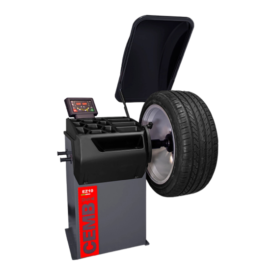
Page 8: Machine Description
Use and maintenance manual 2. Machine description It is used to balance the wheels of cars, vans, 4-WD, motorcycles and scooters. The wheels must weigh less than 75 kg. and, when fitted on the balancing machine, must not interfere with any fixed part of the machine, excluding the shaft and support adaptor. - Page 9 Use and maintenance manual LOCK NUT WHEEL GUARD Machine description...
-
Page 10: Starting
Use and maintenance manual 3. Starting Before switching on the machine, make sure that all the connections described in the INSTALLATION chapter have been made correctly. The following operations involve a potential risk for the operator, given the presence of voltage on the equipment. The Personal Protective Equipment described in the INSTALLATION manual must be worn and work must be done with due care and attention. - Page 11 Use and maintenance manual 7. Position the wheel on the terminal with the inner part facing the balancer. IRON 8. Firmly attach the wheel to the balancer shaft using the lock nut. In the pneumatic version, use the specific collar provided. For operation of the spindle with pneumatic locking (constant thrust air spring) connect the wheel balancer to the compressed air mains.
-
Page 12: Correction Plane Identification
Use and maintenance manual 4. Correction plane identification ▪ Standard dynamic balancing using only clip-on weights: inside plane distance diameter width ▪ Standard dynamic balancing using adhesive weights or a mix of adhesive and clip-on weights: inside plane distance inside plane distance outside inside inside... -
Page 13: Control Panel
Use and maintenance manual Control panel Digital readouts, AMOUNT OF UNBALANCE, inside/outside/static Push button, unbalance reading below the threshold Digital readouts, POSITION OF UNBALANCE, inside/outside/static Push button, selection of correction mode Push button, FUNCTIONS MENU Push button, menu selection confirmation Push button, cycle start Push button, emergency/home Push button, position repeater... -
Page 14: Use Of The Wheel Balancer
Use and maintenance manual 6. Use of the wheel balancer STANDARD BALANCING (clip-on counterweights) 6.1.1 Wheel dimensions setting Using the special grip, move the end of gauge against the rim as shown in the figure: While the gauge is moving the following appears: Hold the gauge in position for at least 2 seconds. - Page 15 Use and maintenance manual In the standard machine setting as VIRTUAL SONAR (AWA and AUTOADAPTIVE enabled), at the end of the automatic distance and diameter measurement, perform a measuring spin. In the case of particular rims, the wheel balancer may ask you to set the tyre width value in mm. Set the width value shown on the tyre and proceed with balancing the wheel.
-
Page 16: Result Of The Measurement And Weight Application
Use and maintenance manual 6.1.2 Result of the measurement and weight application If the unbalance is out of tolerance: 1. When the spin is complete, bring the unbalance into correction position by turning the wheel by hand. The spindle is automatically locked in correction position (if not disabled the wheel lock and for rotation speeds less than 20 rpm). -
Page 17: Balancing With Adhesive Weights (Alu)
Use and maintenance manual BALANCING WITH ADHESIVE WEIGHTS (ALU) 6.2.1 Wheel dimensions setting Using the dedicated grip, move the gauge tip up against the inside of the rim and make two consecutive measure- ments starting from the inside (FI) as shown in the figure. The two preselected positions coincide with the point where the counterweight is to be applied. -
Page 18: Result Of The Measurement And Weight Application
Use and maintenance manual 6.2.2 Result of the measurement and weight application If the unbalance is out of tolerance: 1. When the spin is complete, bring the unbalance into correction position by turning the wheel by hand. The spindle is automatically locked in correction position (if not disabled the wheel lock and for rotation speeds less than 20 rpm) If the acoustic signal is enabled ( ), a beep will sound when the correction... -
Page 19: Balancing With A Mix Of Adhesive And Clip-On Weights And Static Balancing
Use and maintenance manual BALANCING WITH A MIX OF ADHESIVE AND CLIP-ON WEIGHTS AND STATIC BALANCING After dimension acquisition in standard balancing mode, pressing the buttons , you can select one of the following correction modes. WEIGHT APPLICATION POSITION Correction type Inside Outside Clip-on weight at 12 o’clock... -
Page 20: Static Unbalance
Use and maintenance manual STATIC UNBALANCE The static unbalance is shown on display 1 and the relative correction position on the LED display 3 .The correction weight application diameter cannot be set, but is deduced from the dimensions acquired in standard or ALU mode through interpolation algorithms and the use of fixed parameters. Tolerance control is the same as for standard balancing, only that it refers to a single correction plane. -
Page 21: Hide The Adhesive Weights (Split)
Use and maintenance manual HIDE THE ADHESIVE WEIGHTS (SPLIT) SPLIT is only possible in the event of static unbalance or ALU external side and is used to hide any adhesive weights correcting unbalance behind the rim spokes. 1. Perform an unbalance measurement spin. 2. -
Page 22: Unbalance Optimization
Use and maintenance manual UNBALANCE OPTIMIZATION The program allows total wheel out-of-balance to be reduced by compensating, when possible, tyre and rim out- of-balance values. It is suitable for static unbalance values in excess of 30 grams. It requires two runs, rotating the tyre on the rim on the second run. -
Page 23: Setup
Use and maintenance manual 7. Setup MENU ACCESS DIAGRAM This is used to personalise some balancer functions and to perform calibrations. To access this section, press the button. UNBALANCE OPTIMISATION WHEEL DIMENSIONS SETTING diameter mm/inch width mm/inch start from guard closing ON/OFF approximates 1-5g 0.1-0.25oz beep signal... -
Page 24: Self-Diagnostics
Use and maintenance manual SELF-DIAGNOSTICS The machine can perform self-diagnostics to check the LED’s on the control panel and make sure the encoder reads correctly. To perform this operation, view the SETUP menu. In the self-diagnostics sequence, all the LED’s on the panel light up for a few seconds in order to check operation. When the LED’s go out, the machine automatically moves on to the encoder reading phase. -
Page 25: Distance Gauge Calibration
Use and maintenance manual Close the guard and press the button to perform a spin. 4. Turn the wheel until the standard weight is at the top (12 o’clock) and press 5. Turn the wheel until the sample weight is in correspondence to the centre-line of the weight clip and press Pressing the button a default value is set. -
Page 26: Diameter Gauge Calibration
Use and maintenance manual CALIBRATION COMPLETE ▪ Return the gauge to rest position. ▪ The wheel balancer is ready for operation. “r.P.”: In the event of errors or faulty operation, the writing appears on the display : shift the gauge to the rest position and repeat the calibration operation exactly as described above. -
Page 27: Adhesive Weight Width
Use and maintenance manual CALIBRATION COMPLETE ▪ Return the gauge to rest position. ▪ The wheel balancer is ready for operation. In case of errors or malfunctions, the indication of the same step [P.1] or [P2], always reappears on the display. Move the gauge back into rest position and repeat the calibration operation as described above;... -
Page 28: Diagnostics
Use and maintenance manual 8. Diagnostics INCONSISTENT UNBALANCE READINGS In some cases, when a wheel that has just been balanced is repositioned on the balancer, the machine can detect an unbalance. This is not a machine problem but is due to faulty mounting of the wheel on the flange. In other words, when mounting the wheel after initial balancing, it has taken another position with respect to the balancer shaft axis. - Page 29 Use and maintenance manual ▪ Err. 11 Speed too high error Check in self-diagnostics that the encoder functions properly During unbalance measurement rotation, ▪ Replace the computer board wheel speed is more than 270 rpm ▪ Err.14 / Unbalance measurement error Check in self-diagnostics that the encoder functions properly Err.15 / ▪...
-
Page 30: Maintenance
Use and maintenance manual 9. Maintenance GENERAL Before performing any maintenance operations, make sure the machine has been disconnected from the mains power supply. Always use the Personal Protective Equipment indicated in the Installation Manual. 9.1.1 Introductory notes This machine has been designed so as not to require routine maintenance, apart from accurate periodic cleaning. It is important to keep the machine perfectly clean in order to prevent dust or impurities from compromising the operation of the balancer. -
Page 31: Replacing Fuses
Use and maintenance manual 9.1.3 Replacing fuses Some protection fuses are located on the power board (see wiring diagrams) accessible by dismantling the weight shelf). If fuses require replacement, use ones with an identical current intensity. 9.1.4 Cleaning the screen Use a soft cloth and NON-ABRASIVE commercial glass/plastic cleaning spray or ethanol or natural detergents. -
Page 32: Spare Parts
Use and maintenance manual 11. Spare parts 11.1 IDENTIFICATION AND ORDERING METHOD The various parts can be identified using the exploded drawings, the electrical drawings and diagrams in the ma- chine technical file which is archived by the Manufacturer to which a request can be made. For off-the-shelf parts, the technical manuals or the supplier’s original documents can be provided if the Manu- facturer deems this to be useful.
Need help?
Do you have a question about the EZ10 and is the answer not in the manual?
Questions and answers
Screen does not react when interacting with the buttons Also displays a Code not listed in manual 4817