Table of Contents
Advertisement
Available languages
Available languages
Use and maintenance manual
EN
General Index
1.
FOREWORD
1.1
GENERAL
1.2
PURPOSE OF THE MANUAL
1.3
WHERE AND HOW TO KEEP THE MANUAL
1.4
MANUAL UPGRADES
1.5
COLLABORATION WITH USERS
1.6
MANUFACTURER
1.7
MANUFACTURER'S RESPONSIBILITY AND WARRANTY
1.7.1 Terms of warranty
1.8
TECHNICAL ASSISTANCE SERVICE
1.9
COPYRIGHT
2.
MACHINE DESCRIPTION
2.1
PURPOSE
2.2
TECHNICAL SPECIFICATIONS
2.3
DIMENSIONS
3.
STARTING
4.
CONTROL PANEL
5
USE OF THE WHEEL BALANCER
5.1
PRESETTING OF WHEEL DIMENSIONS
5.1.1 Automatic standard setting
5.1.1.1 Automatic width (option)
5.1.2 ALU wheel automatic presetting
5.1.3 Modifying set dimensions
5.1.3.1 Standard correction method
5.1.3.2 Correction method with adhesive weights (ALU)
5.1.4 Correction modes
5.2
MEASUREMENT RESULT
5.3
WHEEL LOCKING
5.4
EXACT POSITIONING OF THE ADHESIVE WEIGHT BY MEANS OF THE GAUGE WITH CLIPS
5.5
SPLIT FUNCTION (HIDDEN WEIGHT)
5.6
AUTOMATIC MINIMIZATION OF STATIC UNBALANCE
6.
SETUP
6.1
MENU
6.2
UNBALANCE OPTIMISATION
6.3
SELF-DIAGNOSTICS
6.4
CALIBRATION
6.5
AUTOMATIC GAUGES CALIBRATION
6.5.1 Rim distance gauge
6.5.2 Diameter gauge
6.5.3 Width sonar (option)
6.6
ADHESIVE WEIGHT WIDTH
3
3
3
3
3
4
4
4
4
5
5
6
6
6
6
7
8
9
9
9
9
9
10
10
10
10
11
11
11
12
12
13
13
14
14
14
15
15
16
16
16
I 1090 - 05/15 - Ver. 00
Advertisement
Table of Contents

Related Manuals for CEMB ER71


Summary of Contents for CEMB ER71
- Page 1 Use and maintenance manual General Index FOREWORD GENERAL PURPOSE OF THE MANUAL WHERE AND HOW TO KEEP THE MANUAL MANUAL UPGRADES COLLABORATION WITH USERS MANUFACTURER MANUFACTURER'S RESPONSIBILITY AND WARRANTY 1.7.1 Terms of warranty TECHNICAL ASSISTANCE SERVICE COPYRIGHT MACHINE DESCRIPTION PURPOSE TECHNICAL SPECIFICATIONS DIMENSIONS STARTING...
- Page 2 DIAGNOSTICS INCONSISTENT UNBALANCE READINGS ALARM SIGNAL MAINTENANCE GENERAL 8.1.1 Introductory notes 8.1.2 Safety rules 8.1.3 Replacing fuses DISPOSAL DISPOSING OF THE BALANCER DISPOSING OF ELECTRONICS COMPONENTS SPARE PARTS 10.1 IDENTIFICATION AND ORDERING METHOD ATTACHED DOCUMENTATION...
-
Page 3: Foreword
Ver. 05-2015 Use and maintenance manual 1. Foreword PURPOSE OF THE MANUAL This manual, and the installation manual, contains the instructions required to use the machine safely and carry out routine maintenance work. Any calibrations, adjustments and extraordinary mainte- WARNING nance operations are not considered in this document as INsTAllATIoN they may only be performed by the service engineer who... -
Page 4: Collaboration With Users
Use and maintenance manual Ver. 05-2015 as a result of regulatory updates or modifications to the in this manual machine. - use of the machine by people who have not read and fully understood the contents of this manual; Any manual upgrades that the manufacturer may see fit to - use in breach of specific regulations in force in the send to users will become an integral part of the manual country of installation;... -
Page 5: Technical Assistance Service
Ver. 05-2015 Use and maintenance manual TECHNICAL ASSISTANCE SERVICE For any technical service operation, contact the manufacturer directly or an authorised dealer always quoting the model, the version and the serial number of the machine. COPYRIGHT The information contained in this manual may not be disclosed to third parties. -
Page 6: Machine Description
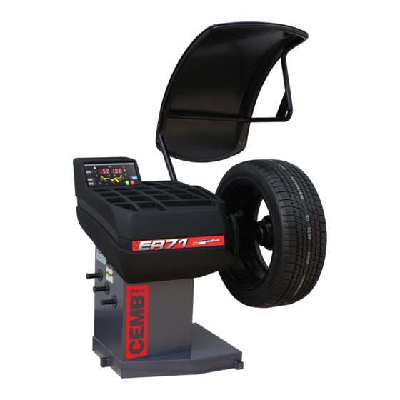
Use and maintenance manual Ver. 05-2015 2. Machine description PURPOSE heavier wheels, fasten it at the points indicated. Do not mount anything other than motorbike, car or truck tyres on the wheel balancer. Thanks to the new and exclusive VDD (Virtual Direct Drive) system, reliable unbalance measurements can be made It is used to balance the wheels of cars, vans, 4-WD, mo- in a short time, almost half the time of the cycle used with... -
Page 7: Starting
Ver. 05-2015 Use and maintenance manual 3. Starting 7. Position the wheel on the terminal with the inner part facing the balancer. WARNING efoRe sWITchING oN The mAchINe mAke suRe ThAT All The INsTAllATIoN coNNecTIoNs descRIbed IN The chApTeR hAve beeN mAde coRRecTly he folloWING opeRATIoNs INvolve A poTeNTIAl RIsk foR The opeRAToR GIveN The pReseNce of volTAGe oN The... -
Page 8: Control Panel
Use and maintenance manual Ver. 05-2015 4. Control panel Digital readouts, AMOUNT OF UNBALANCE, inside/outside Digital readouts, POSITION OF UNBALANCE, inside/outside Push button, selection of mode of correction Push button, unbalance below threshold Push button, FUNCTIONS MENU Push button, menu selection confirmation Push button, cycle start Push button, emergency/home Position repeater push button... -
Page 9: Use Of The Wheel Balancer
Ver. 05-2015 Use and maintenance manual 5 Use of the wheel balancer PRESETTING OF WHEEL DIMENSIONS Set the distance and diameter gauge to the rest position. The balancing machine automatically interprets the pre- The balancing data is set by means of an “intelligent” sence of a rim with clip-on weight correction: automatic gauge;... -
Page 10: Modifying Set Dimensions
Use and maintenance manual Ver. 05-2015 5.1.3.2 Correction method with adhesive weights (ALU) Set the value of the dimensions in sequence: dI=inside weight distance dE=outside weight distance aI=inside weight distance aE=outside weight distance For a different combination of the type or position of the using the buttons weights on the rim, press the buttons near the rim symbol CORRECTION MODES... -
Page 11: Measurement Result
Ver. 05-2015 Use and maintenance manual After dimension acquisition in ALU mode, pressing the If the unbalance is within tolerance, 0 (zero) is display- ed; pressing , you can read the values below the buttons you can select one of the following cor- required tolerance threshold. -
Page 12: Split Function (Hidden Weight)
Use and maintenance manual Ver. 05-2015 ▪ Rotate the gauge until the correction weight adheres To return to the normal unbalance indication press to the rim ▪ The fact that the weight application position is no longer vertical is automatically compensated. To cancel the function, press the button again. -
Page 13: Setup
Ver. 05-2015 Use and maintenance manual 6. Setup MENU This is used to personalise some balancer functions and to perform calibrations. To access this section, press the button. See chapter on UNBALANCE OPTIMISATION See PRESETTING OF WHEEL DIMENSIONS diameter mm/inch width mm/inch start from guard closing on/off... -
Page 14: Unbalance Optimisation
Use and maintenance manual Ver. 05-2015 UNBALANCE OPTIMISATION When optimisation is complete, perform a new spin or press This operation is performed to reduce the static unba- lance of the wheel. the button to return to the measurement screen. It is suitable for static unbalance values in excess of 30 grams. -
Page 15: Automatic Gauges Calibration
Ver. 05-2015 Use and maintenance manual AUTOMATIC GAUGES CALIBRATION 1. Press to view the CALIBRATION 6.5.1 Rim distance gauge function. Display the SETUP menu 2. Add a standard weight of 60 g (2.00 oz) to the outer side, in any position. 1. -
Page 16: Diameter Gauge
Use and maintenance manual Ver. 05-2015 6.5.2 Diameter gauge Display the SETUP menu In case of errors or malfunctions, the indication of the same step [P.1] or [P2], always reappears on the display. Move the gauge back into rest position and repeat the calibration operation as described above;... -
Page 17: Diagnostics
Ver. 05-2015 Use and maintenance manual 7. Diagnostics INCONSISTENT UNBALANCE READINGS In some cases, when a wheel that has just been balanced is repositioned on the balancer, the machine can detect an unbalance. This is not a machine problem but is due to faulty mounting of the wheel on the flange. - Page 18 Use and maintenance manual Ver. 05-2015 WARNING possIble Remedy he INfoRmATIoN IN The columN RequIRes WoRk To be peRfoRmed by specIAlIsT TechNIcIANs oR oTheR AuThoR INsTAllATIoN Ised people Who musT AlWAys WoRk usING The eRsoNAl RoTecTIve quIpmeNT INdIcATed IN The mANuAl N some cAses...
- Page 19 Ver. 05-2015 Use and maintenance manual Err.24 Distance between the spokes less 1. The minimum distance between the spokes where the than 18 degrees. unbalance is to be split must be greater than 18 degrees. 2. Repeat the SPLIT function increasing the distance between the spokes.
-
Page 20: Maintenance
Use and maintenance manual Ver. 05-2015 8. Maintenance GENERAL Specialist staff must be authorised and especially trained concerning the dangers that may arise during operation and the correct methods for avoiding them. They must always work with great care and pay full at- tention. -
Page 21: Disposal
Ver. 05-2015 Use and maintenance manual 9. Disposal 10. Spare parts 10.1 IDENTIFICATION AND ORDERING METHOD cAuTIoN he INsTRucTIoNs IN ThIs chApTeR ARe INdIcATIve efeR To The ReGulATIoNs IN foRce IN The couNTRy WheRe The equIp The various parts can be identified using the explodeddraw- meNT Is used ings, the electrical drawings and diagrams in the machine technical file which is archived by the Manufacturer to... - Page 22 Use and maintenance manual Ver. 05-2015...
- Page 23 Manual de uso y mantenimiento Índice general INFORMACIÓN PRELIMINAR GENERALIDADES OBJETIVO DEL MANUAL DÓNDE Y CÓMO CONSERVAR EL MANUAL ACTUALIZACIÓN DEL MANUAL COLABORACIÓN CON EL USUARIO FABRICANTE RESPONSABILIDAD DEL FABRICANTE Y GARANTÍA 1.7.1 Términos de garantía SERVICIO DE ASISTENCIA TÉCNICA COPYRIGHT DESCRIPCIÓN MÁQUINA FUNCIÓN DEL EQUIPO...
- Page 24 DIAGNÓSTICO INDICACIONES INCONSTANTES DEL DESEQUILIBRIO SEÑALIZACIONES DE ALARMAS MANTENIMIENTO GENERALIDADES 8.1.1 Notas de introducción 8.1.2 Prescripciones de seguridad 8.1.3 Sustitución fusibles DESMANTELAMIENTO DESMANTELAMIENTO DE LA EQUILIBRADORA ELIMINACIÓN DE LOS COMPONENTES ELECTRÓNICOS PIEZAS DE RECAMBIO 10.1 MODO DE IDENTIFICACIÓN Y PEDIDO DOCUMENTACIÓN ADJUNTA...
- Page 25 Ver. 05-2015 Manual de uso y mantenimiento Información preliminar intervenir en la máquina respetando las características técnicas y de diseño para las que se ha fabricado. La lectura de este manual es indispensable, pero no sustituye la competencia del personal técnico, que debe ADVERTENCIA haber obtenido una adecuada formación previa.
- Page 26 Manual de uso y mantenimiento Ver. 05-2015 COLABORACIÓN CON EL USUARIO - modificaciones realizadas en la máquina, en el software o en la lógica de funcionamiento, que no hayan sido autorizadas por el Fabricante por escrito; El fabricante estará a disposición del cliente para propor- - reparaciones no autorizadas;...
- Page 27 Ver. 05-2015 Manual de uso y mantenimiento SERVICIO DE ASISTENCIA TÉCNICA Para cualquier intervención de asistencia técnica, contacte directamente con el Fabricante o el Revendedor autori- zado, citando siempre el modelo, la versión y el número de matrícula de la máquina. COPYRIGHT La información contenida en el manual no debe divulgarse a terceros.
- Page 28 Manual de uso y mantenimiento Ver. 05-2015 Descripción máquina FUNCIÓN DEL EQUIPO indicados. Se aconseja no montar en la equilibradora otros elementos giratorios que no sean neumáticos de Es una máquina equilibradora para ruedas de automóvi- motocicletas, automóviles o camiones. les, vehículos comerciales ligeros, 4 WD, motocicletas y scooters.
- Page 29 Ver. 05-2015 Manual de uso y mantenimiento 3. Accionamiento 7. Colocar la rueda sobre el terminal con la parte interna hacia la equilibradora. ADVERTENCIA NTEs DE DAR TENsIÓN Al EquIpo CompRobAR quE ToDAs INsTAlACIÓN lAs CoNExIÓN DEsCRITAs EN El CApíTulo hAyAN REAlIzADo CoRRECTAmENTE As opERACIoNEs quE sE DEsCRIbEN A CoNTINuACIÓN CoNl lEVAN uN RIEsgo poTENCIAl pARA El opERADoR...
- Page 30 Manual de uso y mantenimiento Ver. 05-2015 4. Panel de mandos Indicadores digitales VALOR DESEQUILIBRIO flanco interno/externo Indicadores digitales POSICION DESEQUILIBRIO flanco interno/externo Indicadores modalidad de corrección seleccionada Tecla lectura desequilibrio inferior al umbral Tecla MENU FUNCIONES Tecla confirmación selección Tecla inicio ciclo Tecla de emergencia/HOME Tecla repetidora de posición...
- Page 31 Ver. 05-2015 Manual de uso y mantenimiento 5. Uso de la equilibradora INTRODUCCIÓN DIMENSIONES RUEDA Lleve el calibre distancia y diámetro en posición de reposo. La máquina interpreta la presencia de una llanta con correc- La introducción de los datos de equilibrado se produce ción mediante ballestilla.
- Page 32 Manual de uso y mantenimiento Ver. 05-2015 5.1.3.2 Método de corrección con contrapesos adhesivos (ALU) Configurar en secuencia el valor de los tamaños: dl=diámetro contrapeso flanco interno dE=diámetro contrapeso flanco externo al=distancia contrapeso flanco interno aE=distancia contrapeso flanco externo utilizando los pulsadores Para una combinación distinta del tipo o de la posición de los contrapesos en la llanta, pulsar las teclas que corresponden al símbolo de la llanta (...
- Page 33 Ver. 05-2015 Manual de uso y mantenimiento Una vez adquiridas las dimensiones en la modalidad ALU, Para el desequilibro en tolerancia se visualiza 0 (cero); pulsando es posible leer los valores que están por presionando las teclas es posible seleccionar uno debajo del umbral de tolerancia previsto.
- Page 34 Manual de uso y mantenimiento Ver. 05-2015 el valor que debe ▪ Girar el calibre hasta que el peso de corrección se adhiera a la llanta utilizando el contrapeso correspondiente. usar se para la corrección en posición 2. ▪ El hecho de que la posición de aplicación del contrape- ▪...
- Page 35 Ver. 05-2015 Manual de uso y mantenimiento 6. Setup MENU’ Permite personalizar algunas funciones de la equilibradora y ejecutar los calibrados. Para acceder a esta sección, pulsar la tecla Véase capítulo OPTIMIZACIÓN DESEQUILIBRIO Véase capítulo INTRODUCCIÓN DIMENSIONES RUEDA mm/pulgada diametro mm/pulgada ancho arranque con cierre...
- Page 36 Manual de uso y mantenimiento Ver. 05-2015 Al finalizar la optimización, efectuar un nuevo lanzamiento o OPTIMIZACIÓN DESEQUILIBRIO Esta operación sirve para reducir el desequilibrio estático pulsar la tecla para regresar al cuadro de medición. de la rueda. Es adecuada para valores de desequilibrio estático superiores a 30 gramos.
- Page 37 Ver. 05-2015 Manual de uso y mantenimiento CALIBRADO CALIBRES AUTOMÁTICOS 1. Pulsar para visualizar la función de 6.5.1 Calibre distancia CALIBRADO. Visualizar el menú SETUP: 2. Agregar un peso de muestra de 60 g (2,00 oz) sobre el flanco externo en una posición cualquiera. 1.
- Page 38 Manual de uso y mantenimiento Ver. 05-2015 6.5.2 Calibre diámetro Visualizar el menú SETUP: En caso de errores o disfunciones, en el display se sigue visualizando la indicación del mismo paso [P.1 ] o [P.2 ]. Llevar el calibre a la posición de reposo y repetir la operación de calibrado prestando atención en seguirla como indicado anteriormente;...
- Page 39 Ver. 05-2015 Manual de uso y mantenimiento Diagnóstico INDICACIONES INCONSTANTES DEL DESEQUILIBRIO En algunos casos, volviendo a colocar en la equilibradora una rueda en la que se acaba de realizar el equilibrado, la máquina puede detectar un desequilibrio. Esto no depende de una disfunción de la máquina, sino de errores de montaje de la rueda en la brida.
- Page 40 Manual de uso y mantenimiento Ver. 05-2015 ADVERTENCIA posIblE soluCIÓN A INfoRmACIÓN quE ApARECE EN lA ColumNA ImplICA INTERVENCIoNEs DEsTINADAs A TéCNICos EspECIAlIzADos o A pERsoNAl AuToRIzADo quE DEbERáN TRAbAjAR sIEmpRE CoN los EquIpos DE pRoTECCIÓN INDIVIDuAl INDICADos EN El mANuAl DE INsTAlACIÓN.
- Page 41 Ver. 05-2015 Manual de uso y mantenimiento Err.14 Error en la medición del desequilibrio. 1. Verificar en el autodiagnóstico el funcionamiento correcto del Err.15 encoder. Err.16 2. Verificar la conexión de los registradores. Err.17 3. Verificar la conexión de tierra de la máquina. Err.18 4.
- Page 42 Manual de uso y mantenimiento Ver. 05-2015 8. Mantenimiento GENERALIDADES El personal, taxativamente especializado, debe estar au- torizado y correspondientemente instruido con respecto a los procedimientos operativos que se deben realizar, las situaciones de peligro que podrían presentarse y los métodos correctos para evitarlas.
- Page 43 Ver. 05-2015 Manual de uso y mantenimiento 9. Desmantelamiento 10. Piezas de recambio 10.1 MODO DE IDENTIFICACIÓN Y PEDIDO ATENCIÓN As INsTRuCCIoNEs DE EsTE CApíTulo soN mERAmENTE INDICA Para la identificación de las distintas piezas hay disponi- TIVAs oNsulTAR lAs NoRmATIVAs VIgENTEs EN El pAís DoNDE bles despieces, esquemas y dibujos en la carpeta técnica sE uTIlIzA El EquIpo de la máquina, guardada por el Fabricante, al que se...
- Page 44 Manual de uso y mantenimiento Ver. 05-2015...
Need help?
Do you have a question about the ER71 and is the answer not in the manual?
Questions and answers