
Related Manuals for Sirius Satellite Radio S-DDH1.1


Summary of Contents for Sirius Satellite Radio S-DDH1.1
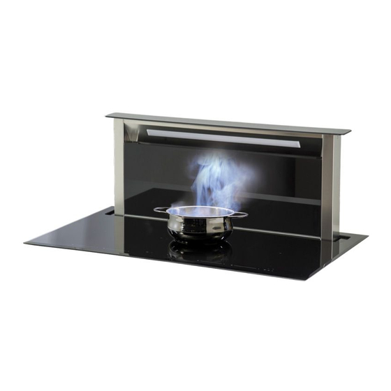
- Page 1 Congratulations on your purchase! Thank you for choosing a Sirius product. S-DDH1.1 INDUCTION DOWNDRAFT INSTALLATION AND OPERATION MANUAL...
-
Page 2: Installation Instructions
DEAR CUSTOMER The built-in induction cooktop is intended for household use only. Materials used for packaging are nature friendly and may be recycled, deposited or destroyed without any threat to the environment. In order to recognize these features, all packing materials are marked with relevant symbols. When you plan to replace your rangehood, deposit your old appliance with the authorized depot dealing with used household appliances. -
Page 3: Table Of Contents
IMPORTANT WARNINGS ABOUT THE COOKING HOB IMPORTANT WARNINGS ABOUT THE DOWNDRAFT TECHNICAL DRAWING INSTALLATION SEQUENCE INSTALLING THE INDUCTION DOWNDRAFT DUCTING TO SEM 7 / SEM 8 MOTOR (SIDE OR BOTTOM VENTING DUCTING TO SEM 7 / SEM 8 MOTOR (FRONT OR REAR VENTING DUCTING FROM MOTOR TO WALL VENT ELECTRICAL CONNECTION CONNECTION TO THE POWER SUPPLY... -
Page 4: Important Warnings About The Cooking Hob
IMPORTANT WARNINGS • Stationary appliances not fitted with means for disconnection from the supply mains having a ABOUT THE INDUCTION COOKTOP contact separation in all poles that provide full disconnection under overvoltage category III, the • The appliance may be installed and connected to instructions state that means for disconnection the power supply only by a qualified technician. -
Page 5: Important Warnings About The Downdraft
IMPORTANT WARNINGS e.g. with a lid or a fire blanket. • If the supply cord is damaged, it must be ABOUT THE DOWNDRAFT replaced by the manufacturer, its service agent or similarly qualified persons in order to avoid a • It is designed to work in both ducted mode with hazard. -
Page 6: Technical Drawing
TECHNICAL DRAWING... -
Page 7: Installation Sequence
INSTALLATION SEQUENCE HOLE CUT FOR INSTALLING THE HOB INSERTION OF THE METAL INSTALLATION STRUCTURE Step 1 Step 2 DOWNDRAFT INSTALLATION COOKING HOB INSTALLATION Step 3 Step 4... -
Page 8: Installing The Induction Downdraft
• The cornice of the worktop can have a thickness greater than the worktop because an opening is S-DDH1.1 maintained in the front part of the kitchen unit of 898mm at least 5mm (refer to design below) to ensure an... - Page 9 • A horizontal and vertical space of at least 20mm Furthermore, carefully read all the instructions as from the lower surface of the cooking hob and at follows: least 20mm from the downdraft must be foreseen • Utilise an air extraction duct that has a maximum so as to create a passage for the air necessary to length of not more than 7 metres.
- Page 10 INSTALLING THE FOAM GASKET INSTALLATION PROCEDURE Before installing the cooking hob in its appropriate • The worktop must be perfectly level. position in the worktop, apply the adhesive gasket in • Place the cooking hob into the previously real expanded polyurethane supplied with the product to ised opening in the worktop.
-
Page 11: Ducting To Sem 7 / Sem 8 Motor
Ducting to SEM 7 motor (200mm ducting) For SEM 8 motor with SDD2 L EMTC 880/1180 - 200mm option only. 1B: Connect a duct expander (Part ‘H’) to rectangular to round adapter (Part ‘A’), then connect length of ducting (Part ‘K.2’) to the 200mm outlet. 2B: Secure to the motor with a universal ring clamp (Part ‘G’). -
Page 12: Ducting To Sem 7 / Sem 8 Motor
INSTALLATION INSTRUCTIONS FOR SEM 7, SEM 8 FRONT OR REAR VENTING (For side or bottom venting instructions, see pages 7 - 9) STEP 2: If venting from front, check to see if front adaptor plate (Part ‘D’) is attached. Remove & replace with cover plate (Part ‘C’) •... - Page 13 STEP 4: 1. Use 200mm ducting (Part ‘K.2’). 2. The ducting fits directly onto the collar on the front adaptor plate (Part ‘D’). 3. Fix in place using a universal ring clamp (Part ‘G’). Ducting to SEM 8 motor (internal motor) PART ‘K.1’...
-
Page 14: Ducting From Motor To Wall Vent
DUCTING FROM MOTOR TO WALL VENT: (SEM 8) 1. Run the length of ducting to the motor. (Additional lengths of ducting can be attached using an additional internal connector pieces.) NOTE: No connector required as it connects directly to the collar of the motor. 2. - Page 15 ELECTRICAL CONNECTION DANGER NOTE If the rangehood presents any anomaly, This appliance complies with the European disconnect the appliance or remove the Directives 2006/95/EC (Low Voltage fuse corresponding to the appliance Directive) and 2004/108/EC (Electromagnetic power disconnecting line. Compatibility). If the appliance has no plug or if the plug is not While installing the appliance and carrying easily accessible, then a device needs to be fitted to maintenance operation, make sure it is disconnected...
-
Page 16: Connection To The Power Supply
CONNECTION TO THE POWER SUPPLY WARNING • Connections may be carried out by a qualified technician only. The earthing Before attempting any repairs on the appliance, protection must comply with the standing disconnect the power supply. In accordance regulations. with the mains voltage the appliance should be •... -
Page 17: Technical Information
TECHNICAL INFORMATION NOTE SDDH1.1 In case sugar or other heavily sweetened Width 898 x 630 substance is spilled on the hotplate, wipe is immediately and remove the sugar residues Rated Voltage 220-240V ~ o 380-415V with a plstic scraper although the cooking 2N~50/60 Hz zone is still hot, otherwise the hotplate may be Type of Switch... - Page 18 Hotplate may be damaged if: Max. pan Min. pan bottom Ø • It is turned on and left empty, or an empty Cooking zones bottom min. Ø dish is placed on it; • You use clay dishes which leave scratches 184x220mm Ø...
- Page 19 ENERGY SAVING TIPS • When buying cookware be careful in selecting size: pot diameter usually refers to the top edge of the dish, which is often larger than the dish bottom. Steam-pressure pots (economic pots), which use pressure in tightly sealed interior, are especially economic, and save both time and energy.
-
Page 20: Induction Cooktop Functions
INDUCTION COOKTOP FUNCTIONS 1. Induction hotplate front left 2. Induction hotplate middle left 3. Induction hotplate middle right 4. Induction hotplate middle 5. Induction hotplate front right 6. Hob control panel 7. Downdraft control unit HOB CONTROL ELEMENTS ON/OFF sensor of cooktop Slide control Power level indicator Warming function sensor... - Page 21 HOB CONTROL • After turning the ceramic glass hob on all displays come on for a moment. The hob is ready for op-eration. • The hob is fitted with electronic sensors which are switched on if you touch the relevant circle for at least one second.
- Page 22 SWITCHING HOTPLATES OFF • Selected hotplate must be activated. • By touching the slide sensor (F) at the start, bring he power setting to “0”. Short beep confirms the OFF position. SWITCHING THE HOB OFF • The hob is switched off by pressing the main (A) sensor. •...
- Page 23 PAUSE FUNCTION NOTE The execution of the function is only possible if at least one zone is on. The pause condition may also be activated with cooking zone specific errors, here, the error display is hidden. Also residual heat indication, special messages such as A, P or no pan are hidden;...
- Page 24 REMAINING HEAT INDICATOR Glass ceramic hob also features remaining heat indicator “H”. Hotplates are not heated directly, but through return heat radiating from the dish. As long as the symbol “H” is on after the hotplate was switched off, the remaining heat may be used for warming up food or for melting.
- Page 25 As soon as the parboiling time is over, the preselected continuous cooking level is valid again. Once the time from the chart below expires, the function is switched off and “A” disappears. You can also switch the automatic cooking mode off anytime by bringingpower setting to “0”. Power setting Max.
- Page 26 WARMING FUNCTION The warming function is used to keep cooked food warm. Hence this function can also be used as melting or simmer function. Activating heating function: • Pressing the special function key (G) of a cooking zone activates the “melting” function. The first LED is activated.
- Page 27 TIMER Use of timer facilitates cooking by setting the time of hotplate operation. Turning timer on • The cooktop must be turned on and the zone where you want to set the timer must be working. • Simultaneously press sensor (D) and (E), the timer’s display shows “0.00”, and the LED to the right of the display, of the first active cooking zone from the left, lights on.
- Page 28 Changing present cooking time • Cooking time can be changed anytime during the operation. • Simultaneously press sensor (E) and (D). • Simultaneously press (D + E) as many times as necessary, to select the zone of which you want to adjust the timer.
- Page 29 - if no cooking zone is active: the alerter’s LED lights on. • The timer value is set by pressing sensors (D) or (E). It’s possible setting time is seconds and minutes also for the alerter: or in hours and minutes. Switching the alarm off When the preset time expires a beep is heard which you can either turn off by touching the (D) or (E) sensors, or leave it to turn off automatically after 2 minutes.
-
Page 30: Safety Function And Error Signals
SAFETY FUNCTIONS AND ERROR SIGNALS ERROR CODE ERROR DESCRIPTION INSTRUCTION MANUAL E03 + continuous Permanent use of keys; Control unit Cleaning of the operational surface. tone, or XXX cuts off after 10 sec. Water or cooking If the problem persists, Contact utensils on the glass above the control authorized center for technical unit. -
Page 31: Cleaning And Maintenance
CLEANING AND MAINTENANCE OF INDUCTION HOB Ceramic glass hob should be cleaned only when completely cooled down, preferably after each use, otherwise even the slightest stains remaining after cooking may burn into the hob surface with each following use. For regular maintenance of ceramic-glass hob use special cleansing agents, produced in such way to create protective film upon the surface. -
Page 32: Using The Downdraft
The product has been designed to extract fumes, grease and cooking steam. It has been designed to work in both suctioning mode, with external venting evacuation, and re-circulating mode. External venting The product can be installed with an external discharge outlet. In this case, install the extraction ducting to the outside of the building (extraction ducting not supplied). -
Page 33: Electrical Connection Of The Downdraft
ELECTRICAL CONNECTION OF THE DOWNDRAFT CAUTION This appliance is fitted with an H05 VVF 3 conductor, 0.75 mm2 (neutral, phase, and ground) power cord. This can be connected up to a 220 - 240 V mono-phase electrical network through a CEI 60083 approved power socket, which must remain accessible after installation, in compliance with installation regulations. - Page 34 ELECTRICAL CONNECTION FUNCTIONS OF THE DOWNDRAFT Light ON/OFF key WARNING The light switches on and off only when the Connecting the product to the mains electricity carriage is fully OPEN. must be carried out by technically qualified and Pressing this button with the carriage closed will specialised personnel.
-
Page 35: Functions Of The Downdraft
TIMER OTHER FUNCTIONS As a result of the new EU65 “Energy label” and Automatic turn off: EU66 “Ecodesign” regulations issued by the After 4 hours of continuous working from the European Commission, which came into force as last setup, the appliance turns off and closes from January 1st, 2015, our products have been austomatically. -
Page 36: Cleaning And Maintenance Of The Downdraft
CLEANING AND MAINTENANCE OF THE DOWNDRAFT Careful maintenance ensures proper operation and good performances over time. CAUTION The hood must be disconnected from the electrical network, both by unplugging the appliance from the socket and activating the magnetic circuit breaker (safety cut-out), before removing the metal grease filters. -
Page 37: After Sales Service
AFTER SALES SERVICE Any maintenance operation on your appliance should NOTE be carried out by: • Either Arisit Pty Ltd; When calling, please mention the appliance • Or a qualified professional technician, authorized details: Production date, (Fig. 9A), Type (Fig. 9B) for that brand if out of warranty. -
Page 38: Installation Guide
INSTALLATION GUIDE FIG. 1 FIG. 2 FIG. 3 FIG. 4 FIG. 5 FIG. 6... - Page 39 FIG. 7 FIG. 8 FIG. 9 FIG. 10 FIG. 11 FIG. 12...
- Page 40 FIG. 13 FIG. 14 FIG. 15 FIG. 16...
-
Page 41: Parts List
PARTS LIST RECTANGULAR TO ROUND DUCTING ADAPTOR SPS-81020 BOTTOM/SIDE COVER COLLAR SPS-51070102735 BOTTOM/SIDE EXIT PLATE SPS-20059000094 FRONT/REAR VENT ADAPTOR SPS-20059120071 FRONT/REAR VENT COVER PLATE SPS-75059000082 UPRIGHT FIXING BRACKETS SPS-77002002999 UNIVERSAL RING CLAMP URC25-215 150MM TO 200MM DUCT EXPANDER GDR 150/200 200MM DIAMETER CONNECTOR PIECE GDC-200 K.2 - DUCTING 200MM... - Page 42 PARTS LIST - INCLUDED PIECES PART A PART B Rectangular to round ducting adaptor Bottom/side cover collar SPS-81020 SPS-51070102735 PART C PART D Bottom/side exit connector Front/rear vent adaptor SPS-20059000094 SPS-20059120071 PART E PART F Front/rear vent cover plate Upright fixing brackets SPS-75059000082 SPS-77002002999...
- Page 43 PARTS LIST - OPTIONAL PIECES To be purchased separately PART G PART H Universal ring clamp 150mm to 200mm Duct expander URC25-215/325 GDR 150/200 Part K.2 PART J 200mm diameter connector piece Semi rigid aluminium ducting 200mm GDC-200 SRPRO 30/200 PART L Ducting connector for SEM 10 installations only Part no.
Need help?
Do you have a question about the S-DDH1.1 and is the answer not in the manual?
Questions and answers