Table of Contents
Advertisement
Quick Links
INSTALLATION
INSTRUCTIONS
CARE AND USE MANUAL FOR:
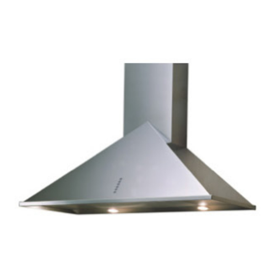
WALL RANGE HOODS
Models covered by this instructions:
SU1 - SU2 - SUE1 - SU3 - SUE3 - SU4 - SU5 - SUE5 - SU7
SU10 - SU22 - SU23 - SU25 - SU26 - SU31 - SU47-P - SU54
SU202/SCH14 - SU207 - SU208 - SU92 - SU36 - SU97
*** BEFORE INSTALLATION ***
ENSURE THERE IS NO VISIBLE OR HIDDEN DAMAGE
SUSTAINED DURING SHIPPING
*** SHIPPING DAMAGE ***
MUST BE REPORTED WITHIN 5 DAYS OF RECEIPT
Advertisement
Table of Contents

Related Manuals for Sirius Satellite Radio SU1


Summary of Contents for Sirius Satellite Radio SU1
- Page 1 WALL RANGE HOODS Models covered by this instructions: SU1 - SU2 - SUE1 - SU3 - SUE3 - SU4 - SU5 - SUE5 - SU7 SU10 - SU22 - SU23 - SU25 - SU26 - SU31 - SU47-P - SU54...
- Page 2 WAR NIN G Thank you for purchasing a Sirius Range Hood. Please read all the instructions in this manual before installing the appliance. Save these instructions for future reference. Only use this appliance as an exhaust ventilation system for the removal of coo- king vapors.
-
Page 3: Table Of Contents
TABLE OF CONTENTS BEFORE YOU BEGIN DUCTING External venting Requirements ELECTRICAL Electrical Supply INSTALLATION Positioning the Range Hood Marking the Fixing Holes for the Range Hood Fixing the Main Support Bracket Hanging the Range Hood Connecting Electricity and Ducting Connecting Chimneys Re-Circulating Requirements OPERATING PROCEDURES General Advice... -
Page 4: Before You Begin
B E F OR E Y OU B E G I N The manufacturer declines all responsibility BEFORE YOU BEGIN: It is advisable to in the event of failure to observe the instruc- test run the range hood before installa- tions given here for installation, maintenan- tion. -
Page 5: Electrical
Maximum Run 6” or 3 1/4 x 10” duct * 100 FT Deduct Each 90 elbow used 15FT Each 45 elbow used Each 6” or 3 1/4 x 10” duct Transition used fig. 2 Each 3” 1/4 x 10” to 6” or 8” Range hoods may interrupt the proper flow of Transition used combustion gases from fireplaces, gas furna-... -
Page 6: Installation
I N S TA L L AT IO N Positioning the Range Hood. Using a sharp object, mark the wall through Determine the center point of the range hood. the template at the center point of the three This is generally the center of the range. Make holes. - Page 7 Before installing the hood is necessary to And fix the box to the just-fit union with two fix the tow motor air outlet union with the screws. screws that are in the accessory bag. Then open the upper cover of the power box.
-
Page 8: Hanging The Range Hood
Only for SU202 – SU207 The bracket fixed onto the back of the range hood will drop into the channel on the top of Fit items “C” before hanging the range hood bracket “S” on the wall. Ensure the hood is - refer to figure 5 for positioning. -
Page 9: Connecting Chimneys
fig. 8 Connect the appropriate length of ducting fig. 10 to the fan exhaust point and join up with the ducting to the exterior. Do not fix the ducting to the range hood exhaust outlet with screws-use duct tape. Figure 9 shows venting directly through the Use duct tape on all joints. -
Page 10: Re-Circulating Requirements
The carbon filter (supplied separately) that absorbs odors is installed behind the alumi- nium grease filter (refer to Fig 14). fig. 12 fig. 11 Connecting the Screen (SU 202 Only). Before attaching the screen the power unit wipe the face of the flange to ensure there is no grit present –... -
Page 11: Operating Procedures
O PE R AT I N G PR O C E DU RES Read all the instructions before operating FUNCTION the appliance. Save these instructions for future reference. “Manual touch buttons Fig. 15” General Advice. A: Light ON/OFF button Ensure that the grease filters are in place. B: Blower Speed 1 (low) or OFF Without these components, operating blo- C: Blower Speed 2 (medium) - Page 12 RC001 Mod. SUTC – Glass (Fig. 17) ADIO ONTROL A: Light switch On/Off Radio control used for the remote operation of B: Reduce speed / OFF motor ducted cooker hoods. C: Luminous telltale D: ON motor/incrase speed TECHNICAL DATA E: 10 - minute timer - Alkaline battery powered: 12 V mod.
- Page 13 Generating a new transmission code: WARNING The radio control system is provided with preset The battery should be replaced every year to codes. Should new codes be required, proceed guarantee the optimal range of the transmitter. as follows: Press simultaneously buttons: To replace the exhausted battery, take the pla- stic lid off, remove the battery and replace it with a new one, observing the correct battery...
-
Page 14: Maintenance
SU Models only: Filter requires washing indi- Use the low speeds for normal use and the cator After 30 hours of use, all the buttons will higher speeds for strong odors and fumes. light up to remind you that the grease filter should be cleaned. -
Page 15: Substitution Of The Led Bar
LED bar with same characteristics. fig. 18 FOR SU1 – SUE1 - SU2 - SU3 - SUE3 - SU4 - SU5 - SUE5 - SU10 - SU22 - SU26 - SU31 - SU36 - SU47-P - SU54 To replace the round LED lamps (fig. -
Page 16: Warranty Service
Three Year Limited Warranty YOU MUST REGISTER THE PURCHASE OF YOUR PRODUCT ON LINE AT www.siriuscappe.com/usa/warranty.htm TO CONVALIDATE YOUR WARRANTY. YOU CAN FIND THE DATA OF YOUR HOODS ON A LABEL INSIDE THE HOOD. JUST REMOVE THE GREASE FILTER TO READ IT. WARRANTY SERVICE To qualify for warranty service, you must notify Sirius After sale service at the email address stated below or call toll free USA 1-877-474-8770 and provide the model number, description...
Need help?
Do you have a question about the SU1 and is the answer not in the manual?
Questions and answers