Table of Contents
Advertisement
Quick Links
Advertisement
Table of Contents

Related Manuals for Bticino 3489GSM


Summary of Contents for Bticino 3489GSM
-
Page 2: Table Of Contents
3489GSM Index PREFACE 1 INTRODUCTION PACKAGE CONTENT TECHNICAL FEATURES MECHANICAL FEATURES LED 27 CONNECTORS PANEL 2 INSTALLATION 2.1 FIRST POWER ON OUTGOING CALL INSERT THE PIN CODE INSERT THE PUK CODE ROAMING CALLS 2.6 BACK-UP BATTERY 2.6.1 REMOVE THE BACK-UP BATTERY 2.7 WALL MOUNT... -
Page 3: Preface
Caution against shocks or vibrations. BACKUP BATTERY WARNING: this device is supplied with a backup battery. This battery may get burnt, explode or cause serious burnings. DO NOT disassemble, weld, burn or throw the battery into water. Keep out of children. Replace only with a same model battery and reserve the operation only to qualified staff. The use of a different battery may cause fire hazard or explosions. Italian laws consider batteries as dangerous urban waste that must be disposed according to the law provisions in force (Italian DPR 915/82 and local provisions). The backup battery is excluded from warranty. DECLARATION of CONFORMITY We, BTicino SpA registered office at: via Messina 38 - 20154 Milano (Italy) declare under our sole responsability that the product with name BT-3489GSM Type: Modem Quad-Band 850/900/1800/1900 MHz, Category: Device for the Information Technology satisfies the basic requirement of the below indicated Directive: 1999/5/EC 9th March 1999, R&TTE (concerning radio equipment and telecommunication terminal equipment and the acknowledgment of their conformity) Law Decree 9th May 2001, n.269, (G.U. n. 156 of 7-7-2001). Directive 2009/125/EC OF of 21 October 2009, ERP, establishing a framework for the setting of ecodesign requirements for energy-related products. EC Regulations n° 278/2009 and n° 1275/2008 As indicated in conformity with the requirements of following Reference Standards or of other regulations documents: EN 301 489-1 EN 301 489-7 EN 301 511 EN 55022... - Page 4 3489GSM The device produces magnetic fields. Do not place it next to magnetic supports such as floppy disks, tapes, etc. Operating your device close to other electrical and electronic equipment - such as a television, phone, radio or a personal computer - may cause interferences. INTERFERENCES The device, like all other wireless devices, is subject to interferences that may reduce its performances. ROAD SAFETY Do not use your device while driving. In case of use on cars, you must check that the electronic equipment is shielded against RF signals. Do not place the device in the air bag deployment area. AIRCRAFT SAFETY Switch off your device when on board aircrafts by disconnecting the power supply and deactivating the internal backup battery. Using GSM devices on aircrafts is illegal. HOSPITAL SAFETY Do not use the device near health equipment, especially pacemakers and hearing aids, in order to avoid potential interferences. Take care when utilizing the device inside hospitals and medical centres, which make...
-
Page 5: Introduction
1 INTRODUCTION GSM/PSTN interface simulates an analog line where the traditional fixed line is not available or where it is not convenient to take it. Thanks to GSM/PSTN interface an analog telephone line is always ready and you can continue to use your traditional communicators without connecting to the fixed line, saving the costs of the analog line. PACKAGE CONTENT • n.1 GSM/PSTN interface • n.1 Switching power supply (IN: 100-240 Vac / 50- 60Hz / 0.5A – OUT 12 Vdc / 1A) •... -
Page 6: Mechanical Features
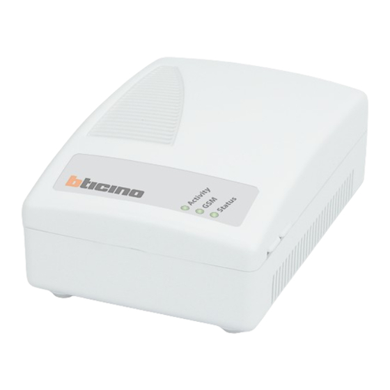
3489GSM MECHANICAL FEATURES • 2 RJ11 Connectors • Plug-in SIM card (1,8V - 3V compatible) • External GSM antenna on SMA/f connector • Bracket for wall mounting • Dimensions: 115 x 80 x 45 mm GSM/PSTN interface has 3 leds that show the different status and situations: STATUS DESCRIPTION Status Device turned OFF or roaming services Device ON and searching for the GSM Network Slow Blinking Device registered to the GSM Network Fast Blinking Active communication GSM OFF GSM Network Searching, Low GSM Signal Level, SIM card not present, PIN not inserted Blinking Good GSM Signal Level Very Good GSM Signal Level Activity OFF Back-up Battery NOT Present (or not connected) Back-up Battery Charging... -
Page 7: Connectors Panel
CONNECTORS PANEL CONNECTOR DESCRIPTION PWR Power supply connector USB connector for upgrades TEL1 / TEL2 RJ11 FXS connectors for communicators Antenna SMA/f connector for external GSM antenna SIM connector Switch Switch for the device power off-on... -
Page 8: Installation
3489GSM 2 INSTALLATION For a correct installation, turn the device off and read the following instructions. TEL1 TEL2 RJ11 ANTENNA Power supply Communicator 1. Connect the GSM antenna found in the package to the SMA connector. In case the interface is installed in combination with an alarm system station, install the antenna at least 1,5 meters from the alarm system station itself. -
Page 9: Outgoing Call
Regular situation: Check the good GSM signal level in order to call and receive the voice call (GSM led ON or Blinking). PIN required: digit the PIN code, described in the following paragraphs. Roaming / Virtual operator: enable the Roaming calls, described in the following paragraphs. OUTGOING CALL Hook off the phone, wait for the dial tone, then digit the phone number. After the last digit GSM/PSTN interface waits for 5 seconds before dialing the phone number; the “#” hash button informs GSM/PSTN interface that the phone number is complete, and it can go on with the call. INSERT THE PIN CODE If the protection PIN code of the SIM card is enabled and the PIN has not been set in the gateway, the Status led is ON and the PIN code request is transmitted to the phone line (double beep repeated with a short pause). -
Page 10: Insert The Puk Code
3489GSM INSERT THE PUK CODE The request for PUK code is signalled with a different special tone with respect to the PIN tone request (double beep repeated with no pause). Insert the PUK code using the phone keypad (set DTMF selection) connected to the TEL1 or TEL2 port: 1. Hook off the phone, you hear the PUK code request tone (double beep with no pause). 2. Enter the PUK code using the phone keypad (using a DTMF phone) and confirm by pressing the “#” (hash) button, followed by a new PIN code with 4 digits, then press “#” again. PUK code#PIN code# (i.e. 12345678#1234#) 3. To cancel the wrong PUK code, hang up before sending the first “#” (hash) button. 4. If the PUK code is correct you will hear the configuration tone (continuous tone repeated twice). 5. Hook on the phone and wait for detection to the GSM network. - Page 11 Codes: ##1111#1#1# to confirm the automatic mode of GSM detection, so, in this case, the roaming mode; (Use this code with SIM card of Virtual GSM Operator, and if the device is installed near the State boundaries and the manually selection of the GSM operator fails.) ##1111#1#2#operator code# to select the manual mode of GSM detection, to a specific GSM oeprator. (Use this code in installation near the State boundaries, to select manually a specific GSM operator) In this last case the operator code consists of 5 digits, and it is the operator code number assigned to each operator worldwide, for example in Italy: 22201 for TIM 22210 for Vodafone 22288 for WIND GSM/PSTN interface can accept also codes different from Italian codes. If the device can detects the specific GSM operator, selected manually, the device will work in regular mode. If the device can not detects the specific GSM operator, GSM/PSTN interface will came back in automatic mode and the roaming situation will be ri-detected the above procedure will be repeated.
-
Page 12: Back-Up Battery
3489GSM BACK-UP BATTERY The battery backup is placed into the product. Back-up Battery features: Ni-Mh 8,4V – 800mAh rechargeable At the first power on, leave the device connected to the power supply for at least 20 hours for a correct and complete battery charging. You will have the best performance in battery autonomy after 2 or 3 cycles of complete charge and discharge. In environment temperature with new batteries the autonomy of device: Standby time: about 6 hours (*) Talk time: about 1 hour and 30 minutes (*) (*) The battery life depends on several factors, i.e. the operating temperature of the device and the quality of GSM signal. 2.6.1 REMOVE THE BACK-UP BATTERY The replacement of battery must be carried out by qualified staff in our maintenance centre. In special cases, to remove the battery disconnect the device from the main power and exclude the battery moving the switch. Open the device, removing the upper and lower cover: there are no screws, you need special tools. Disconnect the connector as shown in picture. Remove the board first, then you will be able to... -
Page 13: Wall Mount
WALL MOUNT GSM/PSTN interface can be installed on a table/desk or wall mounted through the proper bracket for wall mounting. For the wall mounting: 1. Place temporarily the bracket on the wall where you want to install the device and mark the mounting points. 2. Before fixing the bracket to the wall you need to plug it to the device using the two fixing caps supplied in the package. 3. Align the bracket on the back of the device in correspondence of the holes as shown in the picture. -
Page 14: Remote Control Via Sms
3489GSM 3 REMOTE CONTROL VIA SMS The device configuration is performed via SMS; so you can remotely manage the device. It will be possible at any time to remote query the device to know the battery status and the quality of GSM signal. Only authorized users can remote manage GSM/PSTN interface; for every message received it will check the calling number identification. You can remote manage and set the following items: • Phonebook with 4 users authorized to configure the device. • Phonebook with 4 users authorized to receive the informative messages from GSM/PSTN interface. • Battery Low message when the back-up battery has about 90 - 60 minutes autonomy. • Reception of “shutdown in progress” message when the back-up battery has about 30 - 5 minutes autonomy. -
Page 15: List Of Authorized Users: Configuration
3.1.1. LIST OF AUTHORIZED USERS: CONFIGURATION *1 # ID # conf1 , conf2 , conf3 , conf4 # dest1 , dest2 , dest3 , dest4 ITEM DESCRIPTION Key of message to configure the list of authorized users Separation symbol Device ID. Max: 8 alphanumeric characters Default: DIGICOM Separation symbol conf1 Phone number enabled to configure and manage GSM/PSTN interface Separation symbol conf2 Phone number enabled to configure and manage GSM/PSTN interface Separation symbol conf3 Phone number enabled to configure and manage GSM/PSTN interface Separation symbol conf4 Phone number enabled to configure and manage GSM/PSTN interface Separation symbol... -
Page 16: List Of Authorized Users: Configuration Acknowledge Message
3489GSM 3.1.2 LIST OF AUTHORIZED USERS: CONFIGURATION ACKNOWLEDGE MESSAGE When GSM/PSTN interface receives a message, it will check if the message is coming from an authorized users, it will analyze the message; otherwise the message will be ignored. If the message comes from an authorized user, but the text message is wrong, then the device will answer with a NACK message. In case of correct configuration the device will answer with an ACK message. If the list of phone numbers enabled to configure and manage the device is empty (confx), anyone can configure and manage the device. All the messages sent from GSM/PSTN interface, included the ACK and NACK message, will start with an SMS index (Idx_Sms) and a separation symbol (#). The index maximum value can be 255 then it will resume from 0. Example: 12#*1#DIGICOM#ACK 3.1.3 LIST OF AUTHORIZED USERS: CHECK THE CONFIGURATION... -
Page 17: Low Battery: Configuration
3.2.1 LOW BATTERY: CONFIGURATION The user can customize the text “Low Battery” and “Shutdown in progress” with the following message: *2 # First msg text , 60 # Second msg text , 5 # N retry , Time retry ITEM DESCRIPTION Message key to configure the text for low battery Separation symbol First msg text Text of the first message (i.e. Low Battery); the users will receive the message when there are about 90 - 60 minutes left of battery autonomy. Max: 30 characters Default: Low Battery Separation symbol Fixed value Symbol of separation Second msg text... -
Page 18: Low Battery: Configuration Acknowledge Message
3489GSM 3.2.2 LOW BATTERY: CONFIGURATION ACKNOWLEDGE MESSAGE When GSM/PSTN interface receives a configuration message, it will behave as described above, sending the ACK or NACK messages. Example: 16#*2#DIGICOM#ACK 17#*2#DIGICOM#NACK 3.2.3 LOW BATTERY: CHECK THE CONFIGURATION To check the configuration message send the following message: The user requiring the information will receive the answer in the same format, with the Sms index and hash (#) character. Example: 18#*2#DIGICOM#Battery low,60#Shutdown in progress,5#2,1 3.2.4 LOW BATTERY: WARNING MESSAGES When the above mentioned situations occur, if GSM/PSTN interface is correctly configured, it will send the following messages: 14#*B#DIGICOM#Battery Low (Approximately 90 - 60 minutes* of battery autonomy) 15#*B#DIGICOM#Shutdown in progress (Approximately 30 - 5 minutes* of battery autonomy) Key of message Battery low: *B * : The battery life depends on several factors, i.e. the device status (standby mode or talking... -
Page 19: Configuration Reset
CONFIGURATION RESET To recover the factory default configuration of *1 and *2 messages, it will be necessary to send the following SMS: *9 # ID ITEM DESCRIPTION Message ket to recover the factory default configuration Separation symbol Device ID This command will restore all the default values of the SMS configuration. Example: *9#DIGICOM DEVICE REBOOT Authorized users can remote reboot the device with the following message: RESET After the reception of the message, the device answers with an ACK message then it re-boot the device for a new GSM network searching. Example: 18#RESET#DIGICOM#ACK... -
Page 20: Information Request
3489GSM INFORMATION REQUEST Authorized users can request to device information on the GSM operator, the quality of GSM signal and the back-up battery status with the following SMS: INFO GSM/PSTN interface will answers to the user with the following message: Idx_Sms # INFO # ID # G SM operator , GSM strenght # Battery status ITEM DESCRIPTION Idx_SMS Increasing index of SMS sent by GSM/PSTN interface Separation symbol INFO Answer Keyword to an INFO request Separation symbol Device ID Separation symbol GSM operator Name of GSM operator Separation symbol GSM signal GSM signal level, as indicated by GSM led: Low = low GSM signal level... - Page 21 NOTE...
- Page 23 BTicino SpA www.bticino.it Servizio clienti BTicino SpA si riserva il diritto di variare in qualsiasi momento i contenuti illustrati nel presente stampato e di comunicare, in qualsiasi forma e modalità, i cambiamenti apportati.
Need help?
Do you have a question about the 3489GSM and is the answer not in the manual?
Questions and answers